 Weihua Song1,2
 Huice Jiao
- 1State Key Laboratory of Coking Coal Exploitation and Comprehensive Utilization, China Pingmei Shenma Corporation Group, Pingdingshan, Henan, China
- 2College of Mining, Liaoning Technical University, Fuxin, Liaoning, China
The crack closure in impact coal seams induced by high-pressure air blasting greatly affects gas drainage efficiency. The length of the crack closure was calculated and analyzed based on energy and elastic theories. The closure region was then determined to be 3.8 m from the blasting hole. The results of a high-pressure air blasting experiment in the underground of one coal mine in China showed that the effect of crack closure on gas drainage efficiency manifested as a decreased amplitude of gas emission in the crack closure region. At 1.0–4.0 m from the blasting hole, the amplitude of gas emission in the observation holes first increased and then decreased with increasing distance from the blasting hole. At 1.8–2.5 m from the blasting hole, the amplitude of the gas emission was maximal. At 4.0 m from the blasting hole, the crack was nearly closed, and the gas emission in the observation holes was minimal. The theoretical calculation had good consistency with the field test results; thus, it can provide an important reference for an appropriate arrangement of gas drainage boreholes.
1 Introduction
The coal seams in China have large amounts of coal seam gas (Dai et al., 2019; Zou et al., 2019; Huang et al., 2022; Men et al., 2022). However, the existing coal seam gas has not been sufficiently utilized due to its low permeability in the rock mass, geological complexities, and equipment limitations. The Shenyang Coal Science Research Institute pioneered the development of the compressed air blast technique and equipment that has been widely used in China (Li, 2013; Li, 2015). The application of this technique in Huainan Mine showed that the predicted influential area resulting from the compressed air blast was inconsistent with real-world data. This might be attributed to the closure of the fractures, leading to difficulties in gas transport in the rock mass. More specifically, after the compressed air is released, fractures close to the elastic rock mass zone tend to close, resulting in a reduction of the flow channels for coal seam gas transport. These fractures can only be re-opened if the high-pressure gas is pumped through into the rock mass. The present work is a case study of the influence of compressed air blasts on the performance of coal seam gas drainage.
2 Coal failure mechanism due to compressed air blasts
After the compressed air blast, the resulting blasting wave and pressure jointly damage coal through compressive and tensile stresses. The borehole wall is heavily damaged and fractured into small pieces, whereas the rock mass in the distance to the borehole wall forms fractures due to tangential stress. The fracture propagates further into the rock mass and continuously consumes energy provided by the air blast. As a result, the blasting wave-induced energy tends to decrease as it propagates further, leading to formation of only elastic failure in the rock mass (Ning, 2012; Zhang et al., 2017; Gao et al., 2018; Yang et al., 2019).
2.1 Elastic energy consumption Et due to compressed air blasts
Beyond the fracture boundary, only elastic deformation occurs due to the wave blast. The elastic deformation in the unit volume of rock
Thus, the energy consumed due to the elastic deformation is
where
The immediate stress induced on coal when air blasting occurs is calculated according to the following equation:
where
2.2 Fracture closure
After the air blast, the fracture propagates to an extent beyond which the deformation remains elastic. Once the blasting wave energy is completely consumed, the fractures at the boundary between the fracture and elastic deformation zone tend to close under the action of load
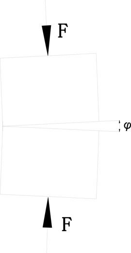
FIGURE 1. Schematic diagram of the fracture closure.
The probability of damage to the microelement of the coal is assumed to be the damage variable D according to
If the rock microelement strength is
where
The fracture closure coefficient
where
Considering the expansion of the fracture resulting from coal seam gas adsorption in the fracture,
where
The effective stress
where
where
During the blasting, the decay of the blasting wave peak in the coal mass is calculated as follows:
Assuming the total force on the coal in the elastic zone results only from the blasting wave,
Considering the conservation of energy, the energy in the elastic zone is not completely released, with most of the energy converted to kinetic energy, while a minor portion is stored in the elastic zone.
The simplified form is
The energy from the elastic zone is assumed to contribute to the fracture closure according to
where
The length of the fracture closure is
The effective closure length in the fracture is
After compressed air blasting, fractures form, leading to an increase in the gas flow channels. In contrast, the fractures close to the elastic zone tend to close, resulting in decreased gas flow channels. Therefore, the borehole for air blasting should be drilled within the fracture propagation zone. In addition, if the borehole height is more than the height of the fracture closure zone, the amount of coal seam drainage decreases greatly.
The effective drainage zone is assumed to be as far as L from the borehole according to
where
The diameter of the loosened area can be calculated as follows (Qian, 2010):
The diameter of the fracture propagation is calculated as follows (Qian, 2010):
As such,
where
3 Field testing
3.1 Site background
The field testing was conducted in the transport roadway in a single coal mine. The compressed air blasting was initiated in a coal seam with a thickness of 3.6 m. The stress from the coal seam gas was 1.6 MPa, and the gas intake was around 6.11 m3/t. The seam was weak and the gas permeability was 0.0111 m2/MPa2·d. The roadway was reinforced by cable bolts and steel mesh.
3.2 Testing methodology
A 0.5-m-deep borehole was drilled into the seam, followed by the installation of the blasting detonation. When the stress reached 60 MPa, the compressed air was released. Two to three blasts were performed in each borehole. Eventually, one drainage borehole and 12 blasting boreholes were formed. In addition, adjacent to the blasting boreholes, another 14 boreholes were drilled for observation (Figure 2). The observation boreholes were drilled 0.5 m deep into the seam with a drill bit 94 mm in diameter. All these boreholes were sealed thereafter. Blasting boreholes were drilled similarly. As soon as the compressed air blasting occurred, the drainage borehole was connected to the gas drainage system. All gas drainage parameters were the same in each borehole. The variations in coal seam gas drainage volume during the drainage were measured. The gas drainage volumes measured in each observation borehole were used to aid in identifying the locations of fracture closure.
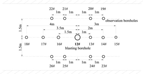
FIGURE 2. Borehole pattern.
3.3 Testing results and analysis
As shown in Table 1 and Figure 3, blasting in 12 blasting boreholes showed increased gas flow in the observation boreholes. The observation boreholes within 2 m of the blasting holes had the largest gas flow. The gas flow decreased from the observation borehole 1 m (borehole 13) to that 1.5 m (borehole 16) from the blasting borehole. The flow then increased to the observation boreholes 1.8 m (boreholes 20, 21, 24, and 25) away from the blasting borehole before decreasing again to the observation boreholes 2 m (borehole 14) and 2.5 m (boreholes 19, 22, 23, and 26) away from the blasting borehole. The gas flow increase peaked at the observation borehole 3 m (borehole 15) from the blasting borehole and reached its minimum in the observation borehole 4 m (borehole 18) from the blasting borehole. The gas flow increase was more obvious in the zone within 3 m from the blasting borehole. The increasing rate of gas intake peaked in the zone 1.8–2.5 m from the blasting borehole. The increasing rate of gas flow peaked in the zone 1.5 m from the blasting borehole. The rate was as high as 55.56%, and the gas drainage was also enhanced most significantly in this area. The gas flow increase tended to decrease more than 2.5 m from the blasting borehole. The increasing rate reached its minimum in the zone 4 m from the blasting borehole, where it was close to the fracture closure zone.
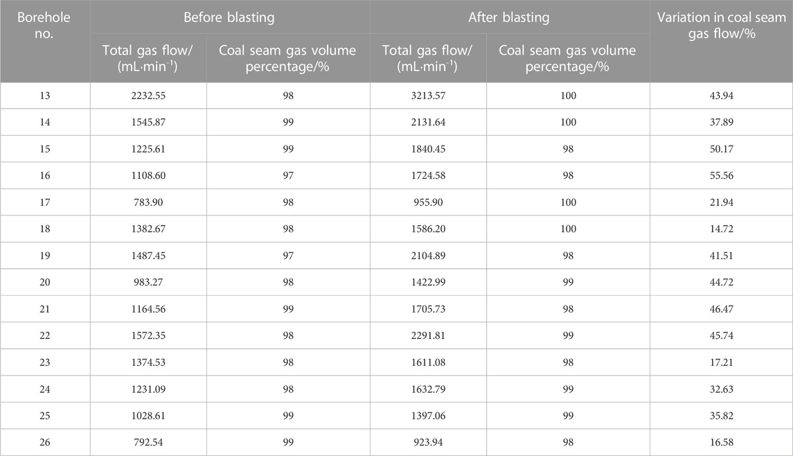
TABLE 1. Variation in coal seam gas flow before and after the compressed air blast.
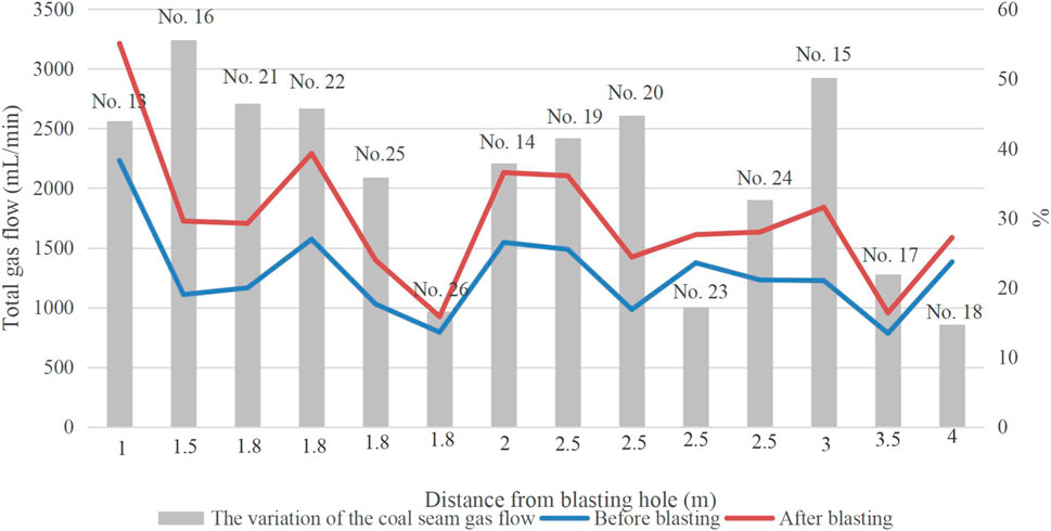
FIGURE 3. Schematic diagram of variations in coal seam gas flow.
After the air blasting, the rate of gas intake tended to increase and then decrease with distance from the blasting borehole. When approaching the fracture closure zone, the increasing rate reached its minimum. The increasing rate of the gas intake on the left-hand side of the blasting borehole was greater than that on the right-hand side. This might be attributed to the orientation of the in situ major principal stress. The observation boreholes above the blasting borehole (boreholes 19–22) had higher gas intake increase rates than those below the blasting borehole (boreholes 23–26). Although the induced stress level at the top and bottom of the blasting borehole by the blasting wave tended to be the same, the induced failure differed, with tensile and compressive failures dominating the top and bottom, respectively. As the tensile strength is always much less than the compressive strength, the influential area resulting from air blasting at the top would be much larger than that at the bottom.
4 Conclusions
a. As a result of compressed air blasting, the huge blasting wave induced extensive fractures that propagated into the coal mass, leading to increased gas flow channels. The gas intake above the air-blasting borehole was higher than that below. The difference in gas intake between the zones on the left and right was attributed to the in situ major principal stress.
b. The compressed air blasting propagated the fractures into the coal mass up to a certain extent, beyond which the coal mass remained intact. The fractures close to the boundary tended to close, leading to decreased gas flow channels. In other words, the real fracture length was always smaller than the theoretical fracture length.
c. The observations of gas flow and intake volumes confirmed that the fracture started closing 4 m from the blasting borehole, a finding consistent with the theoretical value of 3.8 m. This also demonstrated that the theoretical model proposed in this study could predict the fracture length and, hence, aid in coal seam gas drainage prediction. However, the gas migration in the coal seam had the characteristics of an unstable flow field and was also affected by factors such as the construction quality of the drainage hole and the gas flow in the hole. Therefore, further research is needed.
Data availability statement
The raw data supporting the conclusion of this article will be made available by the authors, without undue reservation.
Author contributions
WS wrote the main manuscript text. HJ and YW oversaw the editing of the manuscript. All authors reviewed the manuscript.
Funding
The authors declare that this study received funding from China Pingmei Shenma Corporation Group (Grant No. 41040220181107-2). The funder was not involved in the study design, collection, analysis, interpretation of data, the writing of this article, or the decision to submit it for publication. This project was supported by the Open Research Fund of State Key Laboratory of Coking Coal Exploitation and Comprehensive Utilization.
Conflict of interest
WS and YW were employed by the China Pingmei Shenma Corporation Group.
The remaining author declares that the research was conducted in the absence of any commercial or financial relationships that could be construed as a potential conflict of interest.
Publisher’s note
All claims expressed in this article are solely those of the authors and do not necessarily represent those of their affiliated organizations, or those of the publisher, the editors, and the reviewers. Any product that may be evaluated in this article, or claim that may be made by its manufacturer, is not guaranteed or endorsed by the publisher.
References
Cai, F., Liu, Z. G., and Luo, Y. (2014). Propagation and attenuation characteristics of stress waves generated by explosion in high-gas coal-beds. J. China Coal Soc. 39 (1), 110–114. doi:10.13225/j.cnki.jccs.2013.0218
Cheng, S. F., Ye, Y., Zeng, Y. W., and Gao, R. (2022). Failure law of surrounding rock under underground explosion based on a new damage-virtual tensile crack model. Explos. And Shock Waves 42 (5), 055201. doi:10.11883/bzycj-2021-0414
Chu, H. B., Ren, Z. Q., Yan, S., Zhu, S. Y., Chen, Z., Ye, H. Y., et al. (2022). Experimental study on the propagation and attenuation laws of stress waves in coal under high-pressure gas impact. J. Henan Polytech. Univ. Nat. Sci. 9, 1–6. 1673-9787.2020100040. doi:10.16186/j.carolcarrollnki
Dai, J. X., Qin, S. F., Hu, G. Y., Ni, Y. Y., Gan, L. D., Huang, S. P., et al. (2019). Major progress in the natural gas exploration and development in the past seven decades in China. Petroleum Explor. Dev. 46 (06), 1100–1110. doi:10.1016/s1876-3804(19)60266-1
Gao, K., Liu, Z., and Liu, J. (2018). Propagation law and failure characteristics of blasting stress wave in structural belt coal-rock. J. China Coal Soc. 43, 79–86. doi:10.13225/j.cnki.jccs.2017.0798
Huang, Z. W., Li, G. F., Yang, R. Y., and Li, G. S. (2022). Review and development trends of coalbed methane exploitation technology in China. J. China coal Soc. 47 (9), 3212–3238. doi:10.13225./j.carolcarrollnkiJCCS.SS22.0669
Li, S. G. (2015). Key technology and equipment research and development of improving coal seam permeability by high pres`sure air blasting. Coal Sci. Technol. 43 (2), 92–95. doi:10.13199/j.cnki.cst.2015.02.021
Li, S. G. (2013). Numerical simulation of coal fracture caused by high-pressure air blasting. Saf. Coal Mines 44 (12), 163–165. doi:10.13347/j.cnki.mkaq.2013.12.053
Li, X. L., Li, Z. H., Wang, E. Y., Liang, Y. P., Niu, Y., and Li, Q. G. (2018). Spectra, energy, and fractal characteristics of blast waves. J. Geophys. Eng. 15 (1), 81–92. doi:10.1088/1742-2140/aa83cd
Liu, X. B., Xue, K. S., Luo, Y., Long, K., Liu, Y. N., and Liang, Z. M. (2022). The effect of pore pressure on the mechanical behavior of coal with burst tendency at a constant effective stress. Sustainability 14 (21), 14568. doi:10.3390/su142114568
Men, X. Y., Lou, Y., Wang, Y. B., Wang, Y. Z., and Wang, L. X. (2022). Development achievements of China's CBM industry since the 13th Five-Year Plan and suggestions. Nat. Gas. Ind. 42 (06), 173–178. doi:10.3787/j.issn.1000-0976.2022.06.015
Meng, Y., and Li, Z. P. (2015). Experimental study on the porosity and permeability of coal in net confining stress and its stress sensitivity. J. China Coal Soc. 40 (1), 154–159. doi:10.13225/j.cnki.jccs.2013.1518
Peng, Z., and Zheng, F. (2020). Modal properties of elastic surface waves in the presence of material anisotropy and prestress. J. Sound Vib. 485 (1–2), 115588. doi:10.1016/j.jsv.2020.115588
Qian, Q. H. (2010). Impact and explosion effect in rock and soil. Beijing: National Defense Industry Press.
Vyacheslav, N. R., Lauren, C. G., Sinisha, A. J., Yee, S., and Gino, A. I. (2016). Coal-gas interaction: Implications of changes in texture and porosity. Int. J. Coal Sci. Technol. 3 (1), 10–19. doi:10.1007/s40789-015-0098-6
Xue, J. H., Wang, H. P., Zhou, W., Ren, B., Duan, C., and Deng, D. (2015). Experimental research on overlying strata movement and fracture evolution in pillarless stress-reliefmining. Int. J. Coal Sci. Technol. 2 (1), 38–45. doi:10.1007/s40789-015-0067-0
Yang, R. S., Xu, P., and Chen, C. (2019). Interaction between blast stress waves and cracks. Explos. And Shock Waves 39 (8), 081102. doi:10.11883/bzycj-2018-0480
Zhang, S. C., Zhu, F. H., and Gao, K. (2017). Study on mechanism of deep-hole controlled blasting in coal seam. China Saf. Sci. J. 27 (9), 140–145. doi:10.16265/j.cnki.issn1003-3033.2017.09.024
Keywords: high-pressure air blasting, impact coal seam, gas drainage, crack closure, gas emission
Citation: Song W, Jiao H and Wang Y (2023) Crack closure effect during the impact coal seam with high-pressure air blasting and the influence of gas drainage efficiency. Front. Earth Sci. 11:1131386. doi: 10.3389/feart.2023.1131386
Received: 25 December 2022; Accepted: 21 February 2023;
Published: 08 March 2023.
Edited by:
Chaojun Fan, Liaoning Technical University, ChinaReviewed by:
Xiangjun Chen, Henan Polytechnic University, ChinaJianwei Cheng, China University of Mining and Technology, China
Copyright © 2023 Song, Jiao and Wang. This is an open-access article distributed under the terms of the Creative Commons Attribution License (CC BY). The use, distribution or reproduction in other forums is permitted, provided the original author(s) and the copyright owner(s) are credited and that the original publication in this journal is cited, in accordance with accepted academic practice. No use, distribution or reproduction is permitted which does not comply with these terms.
*Correspondence: Huice Jiao, cGRzamhjQDE2My5jb20=