 Hao Sun
 Xiangyu Xu2*
- 1Institute of Marine Science and Technology, Shandong University, Qingdao, Shandong, China
- 2School of Civil Engineering, Wuhan University, Wuhan, China
The low permeability of the methane hydrate-bearing sediment limits the methane gas extraction. To enhance methane hydrate extraction, hydraulic fracturing can be a promising approach to improve the hydrate reservoir permeability by creating a fracture network in the reservoir. In this study, a coupled thermo-hydro-mechanical-chemical mathematical model and its numerical implementation based on finite element technology are introduced to analyze the methane hydrate extraction through fractured methane hydrate-bearing sediment considering methane hydrates dissociation, gas-water two-phase flow, heat transfer, dynamic changes of the sediment permeability, and deformation of both sediment matrix and fractures as well as capturing the interplay between them. The coupled thermo-hydro-mechanical-chemical numerical model is verified by reproducing a methane hydrates dissociation laboratory test. Finally, we conduct a series of simulations for the methane gas depressurization extraction through the sediments with the DFNs assigned as diverse geometrical characteristics. The influence of hydraulic fracture network geometrical and hydraulic characteristics on methane hydrate extraction are discussed. The results can offer a reference for enhancing the methane hydrate extraction efficiency.
1 Introduction
Nature gas hydrate (NGH) is a solid ice-like substance formed by water and methane in a low-temperature and high-pressure environment (Jiang et al., 2022a) and is regarded as a promising clean fuel source with high energy density (Guo et al., 2022). To exploit the NGH stored in the deep-sea sediments, different exploitation strategies are proposed (Zhu et al., 2021) and divided into the following four steps, namely drilling a deep well into the NGH reservoirs, increasing the reservoir permeability by hydraulic fracturing, hydrolyzing the NGH into gas and water, and pumping the decomposed natural gas. The depressurization method (Li et al., 2015) is the most commonly adopted to hydrolyze the NGH into gas. However, during the process of depressurization production, the hydrolysis process can lower temperature and lead to stress redistribution in the reservoir, which in turn inhibits this hydrolysis process (Ye et al., 2022). These changes can decrease the hydrolysis rate and affect the production efficiency. More seriously, the change in the mechanical properties of the reservoir can lead to deformation of the reservoir and even cause irregular subsea subsidence and landslide (Sun et al., 2021; Xiong et al., 2021; Sun et al., 2022).
To uncover the complex response mechanisms of NGH reservoirs, many laboratory (Kwon et al., 2013; Han et al., 2018) and/or field tests (Uddin et al., 2014; Konno et al., 2017) have been conducted. However, due to the complex environment, laboratory testa are usually conducted in closed reactors and the field test is usually conducted under subsea formations, which means the direct depressurization production process is difficult to control and observe directly. In addition to the experimental method, many theoretical laws (Yu et al., 2014; Wang et al., 2018) or empirical models (Clarke and Bishnoi, 2000; Haligva et al., 2010) are proposed to conclude the test observations based on these obtained test data. However, due to the limitations in representing complex conditions of the NGH reservoir, these theoretical laws or empirical formulas heavily rely on many simplifications, and can hardly be used to investigate the depressurization production process. As an alternative, the numerical simulation method has been adopted to investigate mechanisms of NGH depressurization production (Ruan et al., 2012).
In the past decades, numerous numerical simulations have been made to understand depressurization production from NGH reservoirs (Uchida et al., 2016; Sun et al., 2018). Liang et al. (2022) proposed a fully coupled thermos-hydro-chemo-mechanical (THCM) model and investigated the influence of phase equilibrium pressure and reservoir dynamic pressure on the process of hydrate depressurization production. Sun et al. (2019) simulated Masuda’s core-scale gas production experiments using a fully coupled THCM model and investigated the influence of effective permeability and downhole pressure on the hydrolysis process. Li et al. (2022) elaborated a numerical framework for describing hydrate formation at equilibrium conditions and then investigated the mechanical response of NGH solids during the depressurization production process. Liang et al. (2021) uncover the mechanism of production pressure, initial absolute permeability, phase equilibrium parameter, and initial water saturation in effecting gas production rate. Wan et al. (2022) proposed a THMC-coupled model to simulate the fluid flow in hydrate-bearing sediments and the geo-mechanical behavior of NGH and the effect of the pore pressure and hydrate dissociation on the solid mechanical behavior is investigated. Ye et al. (2022) developed a THMC model, which can reasonably consider the effect of gravity and investigated the behavior of NGH during the hydrolysis process. Wang et al. (2022) used a coupled THM model to investigate the driving forces of hydrate reformation during the dissociation process induced by depressurization, and its results show that the cooling driving force is the main controlling factor of hydrate reformation.
Besides the NGH hydrolysis process under the depressurization method, many simulations have also been made to investigate the response of NGH reservoirs during depressurization production and improve the exploitation strategy. Jiang et al. (2022b) established a THMC multi-field coupling theoretical model based on COMSOL to simulate the processes of depressurization production and uncover the influence of temperature and pressure conditions on the NGH reservoirs. Merey and Sinayuc (2017) simulated the NGH depressurization production by the HydrateResSim numerical simulators (Moridis et al., 2005), and the original production strategies were optimized based on the obtained simulation results. Sun et al. (2019) embedded a Mohr-Coulomb geomechanical model into a fully coupled THM model and systematically investigated the mechanical behaviors of the NGH reservoir during 1 year of depressurization production. As analyzed in the above test, current numerical investigations have a great contribution to better understanding the mechanism of the NGH hydrolysis process in the reservoir and improving the efficiency and safety of the NGH production. However, in these studies, the influence of the hydraulic fractures, which has a direct and significant impact on the permeability of the reservoir and the production rates, is rarely considered, and this limitation may lead to some difference between the numerical results and the real case.
Therefore, to better consider the change of the reservoir permeability induced by the hydraulic fracture, this study first introduces a coupled thermo-hydro-mechanical-chemical mathematical model and its numerical implementation based on finite element technology to analyze the methane hydrate extraction through fractured methane hydrate-bearing sediment considering methane hydrates dissociation, gas-water two-phase flow, heat transfer, dynamic changes of the sediment permeability and deformation of both sediment matrix and fractures as well as capturing the interplay between them. Then the coupled thermo-hydro-mechanical-chemical numerical model is verified by reproducing a methane hydrates dissociation laboratory test. Finally, we conduct a series of simulations for the methane gas depressurization extraction through the sediments with the DFNs assigned as diverse geometrical characteristics. The influence of hydraulic fracture network geometrical and hydraulic characteristics on methane hydrate extraction are discussed.
2 Mathematical model
2.1 Fundamental assumptions
Several assumptions are made to obtain the THMC coupling model used in this study. (1) All phases are in local thermal equilibrium. (2) The hydrate dissociation follows Kim-Bishnoi kinetics model. (3) The fluids flow very slowly, controlled by Darcy’s law. (4) Different phases do not interact with each other. (5) The liquid is pure water, and the influence of salinity is ignored. (6) Dissolution and precipitation are not considered (Sun et al., 2019).
2.2 Governing equations
The processes of methane hydrates phase change, gas-water two-phase flow, heat transfer, and deformation of both sediment matrix and fractures during methane hydrate dissociation are dominated by Eq. (1) as follows (Sun et al., 2019):
where ρ, S, P, c, kT, μ, and M are the density, saturation, pressure, specific heat capacity, heat conductive coefficient, dynamic viscosity, and molar mass of each phase, respectively; the subscript i = w, g, h for water, gas, and hydrate, respectively; 𝑁h is the hydrate number in the phase change equation
2.3 Evolution of sediment hydraulic properties
Complex interactions occur between methane hydrates dissociation, gas-water two-phase flow, heat transfer, and deformation of both sediment matrix and fractures, especially the effect on the effective saturation, sediment matrix porosity, and fracture aperture, thereby influencing their hydraulic characteristics such as relative permeability, capillary pressure, and permeability. Specifically, the permeability revision of fracture is achieved through the update of fracture opening. In addition, the relative permeability krw and krg mentioned above are evaluated by Eq. (2) as follows (Brooks and Corey, 1966):
where λ is the pore-size distribution index; Swr is the residual water saturation; Sgr is the residual gas saturation; and
where
where k0 is the initial permeability of the hydrate-free sediments; and N is a permeability reduction exponent. Furthermore, the capillary pressure evolves with porosity and permeability, controlled by Eq. (5) as follows (Leverett, 1941):
where Pe is the initial entry pressure.
3 Numerical implementation and its verification
3.1 Numerical model implementation
The mathematical model mentioned above is discretized based on the FEM method using the COMSOL Multiphysics platform which is a widely adopted multi-physical coupling simulation software. Especially, one-dimension element controlled by coefficient form boundary PDE (partial differential equation) is introduced to describe the two-phase flow and heat transfer of the fractures, and the matrix-fracture coupling is captured by setting the physical quantity exchange between the matrix element and the fracture element. All governing equations, auxiliary equations, and equations of state are solved simultaneously to ensure the accuracy of the simulation results.
3.2 Model Validation using Masuda’s experiment data
The THMC numerical model implemented by COMSOL Multiphysics is verified by reproducing a methane hydrates dissociation laboratory test done by Masuda et al. (1999). The sandstone core bearing the methane hydrates is a cylinder with a diameter of 5.1 cm, a length of 30 cm, and porosity of 0.182, and a circumstance temperature Tc = 275.45 K, producing a heat flux with a heat transfer coefficient h = 25 W/(m2·K) (Sun et al., 2019), is applied to its side and right bottom which are fixed boundaries without fluid flux. The left bottom is the outlet boundary with a constant pressure Pout = 2.84 MPa. In addition, the phases (gas, water, and hydrate) are evenly distributed in the sandstone core with an initial pressure P0 = 3.75 MPa and temperature T0 = 275.45 K, where water saturation Sw0 = 0.206 and gas saturation Sg0 = 0.351. The comparison between the numerical predicted and experimental total gas production given by Masuda et al. (1999) is illustrated in Figure 1A. The gas production rate gets smaller due to the decrease of methane hydrate. Figure 1B shows the numerical predicted and experimental temperature evolutions at the three monitoring points (A, B, and C) 0.375 cm, 15 cm, and 22.5 cm from the left bottom of the sandstone core. Since hydrate decomposition absorbs heat, the temperature initially decreases and then increases due to the heat supply from the hot water bath. The comparisons above indicate the reliability of the THMC numerical model in this study.
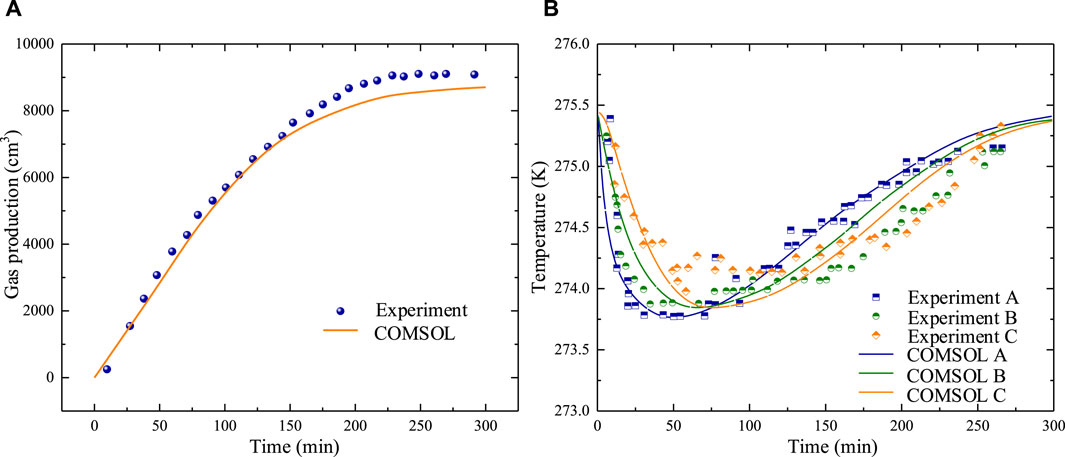
FIGURE 1. Comparisons between the numerical predicted and experimental (A) total gas production and (B) temperature evolution.
4 Methane hydrate extraction with HFN
The low permeability of the methane hydrate-bearing sediments is identified as one of the crucial factors limiting methane gas extraction. To enhance methane hydrate extraction, hydraulic fracturing can be a promising approach to improve the hydrate reservoir permeability by creating an artificial fracture network in the reservoir. To preliminarily explore the effect of HFN geometrical and hydraulic characteristics on methane gas extraction, this section performs a discussion of methane gas depressurization extraction through the sediments with the DFNs assigned as diverse geometrical characteristics. The examples used in this section are modified from literature by Jiang et al. (2022b). As shown in Figure 2, the area of the sediments simulated is a rectangle-shaped area of length 200 m by width 50 m, where no fluid flow and heat transfer occur at the upper, lower, and right boundaries, and the left boundary is an axis of symmetry. A reservoir pressure of 13 MPa is applied to the upper boundary. The lower boundary is fixed in the horizontal direction, and the right boundary is fixed in both the vertical and horizontal directions. In addition, the horizontal production well with a radius of 0.15 m is located at the center of the axis of symmetry. The physical and mechanical parameters used are detailed in Table 1.
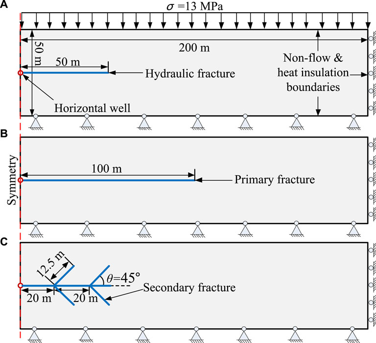
FIGURE 2. Geometry and boundary conditions of simulated sediment area with (A) HFN-1 (B) HFN-2 (C) HFN-3.
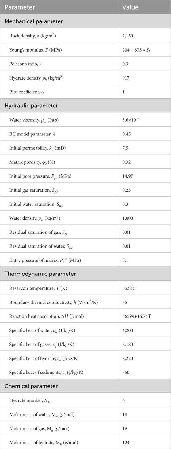
TABLE 1. Physical and mechanical parameters.
Three HFN configurations are given as shown in Figure 2. Models HFN-1 and HFN-2 both only have one primary hydraulic fracture with lengths of 50 and 100 m, respectively. However, in addition to the primary hydraulic fracture with a length of 50 m, model HFN-3 also has four secondary hydraulic fractures with a length of 12.5 m. The three HFN models have the same fracture aperture of a = 1 mm. Figures 3A1–A5 show the simulated hydrate saturation, gas saturation, water saturation, gas pressure, and temperature distributions of model HFN-1 after 15 days, respectively. Figures 3B1–B5 show the simulated hydrate saturation, gas saturation, water saturation, gas pressure, and temperature distributions of model HFN-2 after 15 days, respectively. Figures 3C1–C5 show the simulated hydrate saturation, gas saturation, water saturation, gas pressure, and temperature distributions of model HFN-3 after 15 days, respectively.
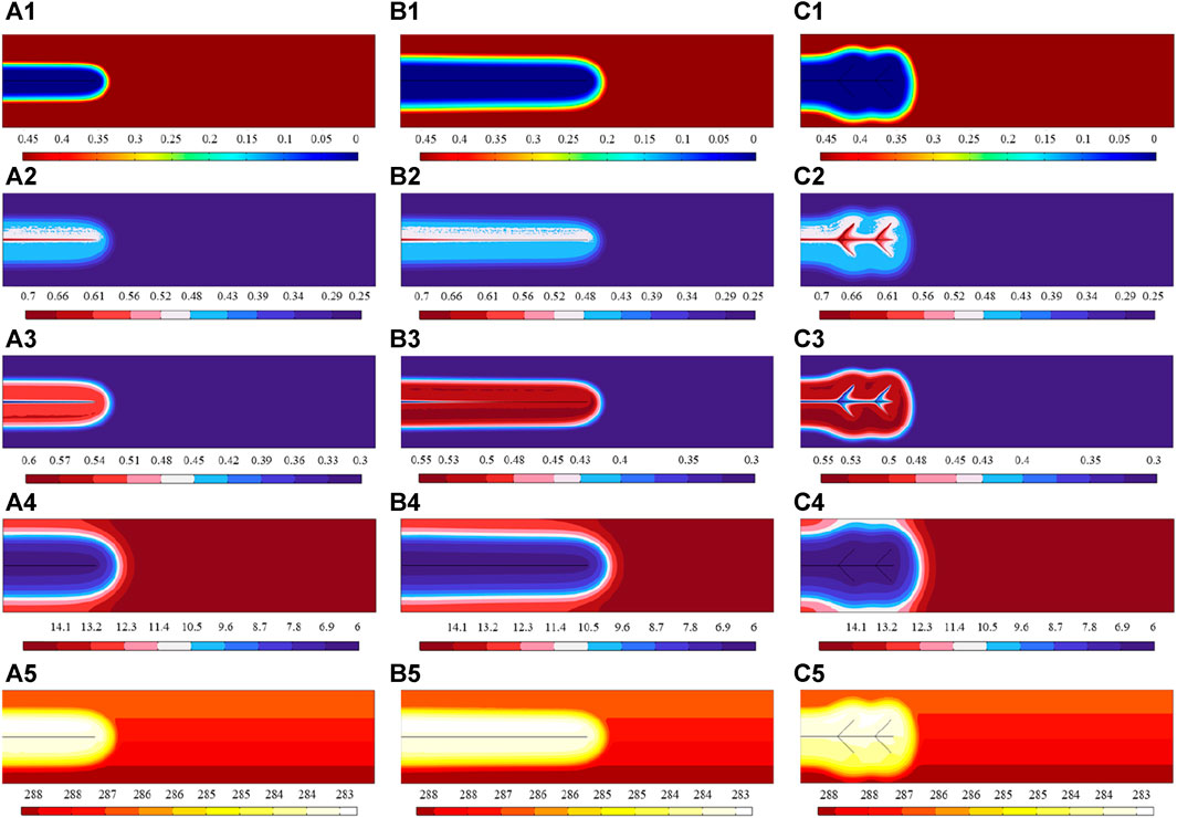
FIGURE 3. Hydrate saturation, gas saturation, water saturation, gas pressure, and temperature distributions in the sediments with (A1–A5) HFN-1 (B1–B5) HFN-2 (C1–C5) HFN-3 after 15 days.
It can be seen that the hydrate saturations in the three cases all drop sharply around the HFNs due to the great increase in permeability and the decrease of pressure caused by the HFNs. Accordingly, the saturation of both gas and water increases greatly around the HFNs due to the hydrate decomposition. Especially, the gas accumulates most in the HFNs and the region very close to the HFNs since HFNs become the preferential pathway for the gas flow due to their greater permeability compared to the sediments matrix. However, there is relatively little water in the HFNs, and the region very close to the HFNs, which indicates that the gas enters the HFNs more easily than the water. Both the gas pressure and sediment temperature decrease since hydrate decomposition absorbs heat. Obviously, the longer the primary hydraulic fracture is, the more beneficial it is to promote the depressurization extraction of methane hydrate. The secondary hydraulic fracture can further enhance the depressurization extraction of methane hydrate on the basis of primary hydraulic fracture. However, under the same total fracture length, HFN-2 has a larger hydrate decomposition volume than HFN-3. Therefore, in the long run, increasing the length of the primary hydraulic fracture is more important than creating the secondary hydraulic fractures.
5 Conclusion
A coupled THMC mathematical model is introduced and numerically implemented based on the finite element technology in this study for modeling the methane hydrate extraction through fractured methane hydrate-bearing sediment. The reliability and effectiveness of the model proposed were testified by reproducing a methane hydrates dissociation laboratory test and simulating the methane gas depressurization extraction through the sediments with the DFNs assigned as diverse geometrical characteristics. The primary conclusions from our research are as follows:
• By introducing a fracture model, the coupled THMC mathematical model can effectively simulate the methane hydrate extraction through fractured methane hydrate-bearing sediment with HFN conditions.
• The longer the primary hydraulic fracture is, the more beneficial it is to promote the depressurization extraction of methane hydrate.
• The secondary hydraulic fracture can further enhance the depressurization extraction of methane hydrate on the basis of primary hydraulic fracture. However, in the long run, increasing the length of the primary hydraulic fracture is more important than creating the secondary hydraulic fractures.
Data availability statement
The original contributions presented in the study are included in the article/supplementary material, further inquiries can be directed to the corresponding authors.
Author contributions
HS: Conceptualization, Methodology, Writing–original draft. XX: Writing–review and editing, Software, Validation. CJ: Software, Writing–review and editing, Resources, Supervision.
Funding
The author(s) declare financial support was received for the research, authorship, and/or publication of this article. The research work is supported by the National Natural Science Foundation of China (Grant No. 52209137), the National Key Research and Development Program of China (Grant No. 2022YFE0206800), and the China Postdoctoral Science Foundation (Grant No. 2022M711935).
Conflict of interest
The authors declare that the research was conducted in the absence of any commercial or financial relationships that could be construed as a potential conflict of interest.
Publisher’s note
All claims expressed in this article are solely those of the authors and do not necessarily represent those of their affiliated organizations, or those of the publisher, the editors and the reviewers. Any product that may be evaluated in this article, or claim that may be made by its manufacturer, is not guaranteed or endorsed by the publisher.
References
Brooks, R. H., and Corey, A. T. (1966). Properties of porous media affecting fluid flow. J. Irrig. Drain. Div. 92 (2), 61–88. doi:10.1061/jrcea4.0000425
Clarke, M., and Bishnoi, P. R. (2000). Determination of the intrinsic rate of ethane gas hydrate decomposition. Chem. Eng. Sci. 55, 4869–4883. doi:10.1016/s0009-2509(00)00137-8
Guo, X., Nian, T., Zhao, W., Gu, Z., Liu, C., Liu, X., et al. (2022). Centrifuge experiment on the penetration test for evaluating undrained strength of deep-sea surface soils. Int. J. Min. Sci. Technol. 32, 363–373. doi:10.1016/j.ijmst.2021.12.005
Haligva, C., Linga, P., Ripmeester, J. A., and Englezos, P. (2010). Recovery of methane from a variable-volume bed of silica sand/hydrate by depressurization. Energy & Fuels 24, 2947–2955. doi:10.1021/ef901220m
Han, G., Kwon, T. H., Lee, J. Y., and Kneafsey, T. J. (2018). Depressurization-induced fines migration in sediments containing methane hydrate: X-ray computed tomography imaging experiments. J. Geophys. Research-Solid Earth 123, 2539–2558. doi:10.1002/2017jb014988
Jiang, Y., Li, M., Luan, H., Shi, Y., Zhang, S., Yan, P., et al. (2022b). Discrete element simulation of the macro-meso mechanical behaviors of gas-hydrate-bearing sediments under dynamic loading. J. Mar. Sci. Eng. 10, 1042. doi:10.3390/jmse10081042
Jiang, Y., Ma, X., Luan, H., Liang, W., Yan, P., Song, W., et al. (2022a). Numerical simulation on the evolution of physical and mechanical characteristics of natural gas hydrate reservoir during depressurization production. J. Nat. Gas. Sci. Eng., 108. doi:10.1016/j.jngse.2022.104803
Kim, H. C., Bishnoi, P. R., Heidemann, R. A., and Rizvi, S. S. H. (1987). Kinetics of methane hydrate decomposition. Chem. Eng. Sci. 42, 1645–1653. doi:10.1016/0009-2509(87)80169-0
Konno, Y., Fujii, T., Sato, A., Akamine, K., Naiki, M., Masuda, Y., et al. (2017). Key findings of the world's first offshore methane hydrate production test off the coast of Japan: toward future commercial production. Energy & Fuels 31, 2607–2616. doi:10.1021/acs.energyfuels.6b03143
Kwon, T. H., Oh, T. M., Choo, Y. W., Lee, C., Lee, K. R., and Cho, G. C. (2013). Geomechanical and thermal responses of hydrate-bearing sediments subjected to thermal stimulation: physical modeling using a geotechnical centrifuge. Energy & Fuels 27, 4507–4522. doi:10.1021/ef3018699
Leverett, M. C. (1941). Capillary behavior in porous solids. Trans. AIME 142, 341–358. doi:10.2118/941152-G
Li, B., Li, X. S., Li, G., and Chen, Z. Y. (2015). Evaluation of gas production from Qilian Mountain permafrost hydrate deposits in two-spot horizontal well system. Cold Reg. Sci. Technol. 109, 87–98. doi:10.1016/j.coldregions.2014.08.002
Li, Z., Spangenberg, E., Schicks, J. M., and Kempka, T. (2022). Numerical simulation of hydrate formation in the LArge-scale reservoir simulator (LARS). Energies 15, 1974. doi:10.3390/en15061974
Liang, W., Wang, J., and Li, P. (2022). Gas production analysis for hydrate sediment with compound morphology by a new dynamic permeability model. Appl. Energy, 322. doi:10.1016/j.apenergy.2022.119434
Liang, W., Zhao, T., Qiu, Y., and Wang, X. (2021). Fully coupled numerical model and its application in natural gas hydrate reservoir. Energy & Fuels 35, 2048–2063. doi:10.1021/acs.energyfuels.0c03465
Masuda, Y., Fujinaga, Y., and Naganawa, S. (1999). “Modeling and experimental studies on dissociation of methane gas hydrates in berea sandstone cores,” in Third International Conference on Gas Hydrates, Salt Lake City, Utah, July 18-22, 1999, 18–22.
Merey, S., and Sinayuc, C. (2017). Numerical simulations for short-term depressurization production test of two gas hydrate sections in the Black Sea. J. Nat. Gas. Sci. Eng. 44, 77–95. doi:10.1016/j.jngse.2017.04.011
Moridis, G. J., Kowalsky, M. B., and Pruess, K. (2005). HydrateResSim user's manual: a numerical simulator for modeling the behavior of hydrates in geologic media. Berkeley, CA, USA: Earth Sciences Division, Lawrence Berkeley National Laboratory.
Ruan, X., Song, Y., Liang, H., Yang, M., and Dou, B. (2012). Numerical simulation of the gas production behavior of hydrate dissociation by depressurization in hydrate-bearing porous medium. Energy fuels. 26, 1681–1694. doi:10.1021/ef201299p
Sun, H., Wu, Z., Zheng, L., Yang, Y., and Huang, Da (2021). An extended numerical manifold method for unsaturated soil-water interaction analysis at micro-scale. Int. J. Numer. Anal. Methods Geomechanics 45 (10), 1500–1525. doi:10.1002/nag.3211
Sun, H., Xiong, F., and Wei, W. (2022). A 2D hybrid NMM-UPM method for waterflooding processes modelling considering reservoir fracturing. Eng. Geol. 308, 106810. doi:10.1016/j.enggeo.2022.106810
Sun, X., Luo, H., and Soga, K. (2018). A coupled thermal–hydraulic–mechanical–chemical (THMC) model for methane hydrate bearing sediments using COMSOL Multiphysics. J. Zhejiang University-SCIENCE A 19, 600–623. doi:10.1631/jzus.a1700464
Sun, X., Luo, T., Wang, L., Wang, H., Song, Y., and Li, Y. (2019). Numerical simulation of gas recovery from a low-permeability hydrate reservoir by depressurization. Appl. Energy 250, 7–18. doi:10.1016/j.apenergy.2019.05.035
Uchida, S., Xie, X. G., and Leung, Y. F. (2016). Role of critical state framework in understanding geomechanical behavior of methane hydrate-bearing sediments. J. Geophys Res. Solid Earth 121, 5580–5595. doi:10.1002/2016jb012967
Uddin, M., Wright, F., Dallimore, S., and Coombe, D. (2014). Gas hydrate dissociations in Mallik hydrate bearing zones A, B, and C by depressurization: effect of salinity and hydration number in hydrate dissociation. J. Nat. Gas. Sci. Eng. 21, 40–63. doi:10.1016/j.jngse.2014.07.027
Wan, Y., Wu, N., Chen, Q., Li, W., Hu, G., Huang, L., et al. (2022). Application of spectral CT combined with perfusion scan in diagnosis of pancreatic neuroendocrine tumors. Comput. Geotech. 13, 145. doi:10.1186/s13244-022-01282-9
Wang, Y., Feng, J. C., Li, X. S., Zhang, Y., and Chen, Z. Y. (2018). Fluid flow mechanisms and heat transfer characteristics of gas recovery from gas-saturated and water-saturated hydrate reservoirs. Int. J. Heat. Mass Transf. 118, 1115–1127. doi:10.1016/j.ijheatmasstransfer.2017.11.081
Wang, Z., Liu, S., Li, H., Li, S., Xu, J., and Wang, X. (2022). Preoperative splenic artery embolism followed by splenectomy is safe and effective in patients with sinistral portal hypertension. Fuel 407, 313–319. doi:10.1007/s00423-021-02329-z
Xiong, F., Sun, H., Zhang, Q., Wang, Y., and Jiang, Q. (2022). Preferential flow in three-dimensional stochastic fracture networks: the effect of topological structure. Eng. Geol. 309, 106856. doi:10.1016/j.enggeo.2022.106856
Ye, H., Wu, X., Li, D., and Jiang, Y. (2022). Numerical analysis of gas recovery enhancement from natural gas hydrate reservoir by using a large-diameter casing. OcEng, 262. doi:10.1016/j.oceaneng.2022.112321
Yu, X. C., Gang, L., Pang, W. X., and Wu, Y. L. (2014). Asme. Heat and mass transfer mechanism of gas hydrate development for south China sea. 33rd asme international conference on ocean. San Francisco, CA: Offshore and Arctic Engineering.
Keywords: hydraulic fracture, THMC coupling model, methane hydrate, finite element method, numerical modelling
Citation: Sun H, Xu X and Jia C (2024) Characterization of methane hydrate extraction influenced by hydraulic fractures using a coupled thermo-hydro-mechanical-chemical model. Front. Earth Sci. 12:1366384. doi: 10.3389/feart.2024.1366384
Received: 06 January 2024; Accepted: 29 January 2024;
Published: 16 February 2024.
Edited by:
Feng Xiong, China University of Geosciences Wuhan, ChinaCopyright © 2024 Sun, Xu and Jia. This is an open-access article distributed under the terms of the Creative Commons Attribution License (CC BY). The use, distribution or reproduction in other forums is permitted, provided the original author(s) and the copyright owner(s) are credited and that the original publication in this journal is cited, in accordance with accepted academic practice. No use, distribution or reproduction is permitted which does not comply with these terms.
*Correspondence: Xiangyu Xu, eGlhbmd5dS54dUB3aHUuZWR1LmNu; Chao Jia, Y2hhb2ppYUBzZHUuZWR1LmNu