 Vasyl Lozynskyi
 Khalidilla Yussupov3*
 Kanay Rysbekov
 Oleg Bazaluk
- 1Belt and Road Initiative Center for Chinese-European Studies (BRICCES), Guangdong University of Petrochemical Technology, Maoming, China
- 2Department of Mining Engineering and Education, Dnipro University of Technology, Dnipro, Ukraine
- 3Department of Mining, Satbayev University, Almaty, Kazakhstan
- 4Mining and Metallurgical Institute Named After O.A. Baikonurov, Satbayev University, Almaty, Kazakhstan
- 5Institute of Geology and Oil and Gas Business, Caspian University, Almaty, Kazakhstan
Introduction: The research concerns how making cut cavities improves drilling and blasting operations as well as the optimum parameters to arrange both snubber and auxiliary blastholes.
Methods: The research methods include experimental and industrial activities to identify the optimum depth of the first-section snubber blastholes relative to the second-section blastholes. It also identifies optimum parameters of the snubber blastholes while driving mine workings and ore breaking in stopes with different mine working sections and different rock mass strengths broken using the technique of cut-cavity formation.
Results and Discussion: Experimental explosions executed in a production environment have proved the efficiency of the proposed technique of sectional formation of a cut cavity, which helped increase the blasthole use coefficient (BUC) from 0.88 to 0.97. The depth of the first-section boreholes should be determined relative to the length of the second-section boreholes and the broken rock mass strength. The higher the strength of the broken formation, the larger the ratio between the first and the second-section blasthole lengths should be. The results of the experimental explosions indicate that the depth of first-section snubber blastholes varies from 0.5 and more of the second-section boreholes, depending upon the depth of the latter and the broken rock mass strength. If the strength of the broken rock mass is 12 on the Protodyakonov scale, and the second-section blasthole depth increases from 1.6 m to 2.6 m, then the depth of the second-section boreholes should be increased from 0.9 m to 1.54 m so as to be 0.55–0.56 of the second section blasthole length. If the strength of the broken rock mass is 18, and the length of the second section increases from 1.8 m to 2.82 m, then the first-section length varies from 0.9 m to 1.75 m, being 0.5–0.62 of the second section blasthole length. Applying the novel proposed procedure for a cut-cavity formation will increase the blasthole use coefficient and reduce the cost of drilling and blasting operations. Moreover, the procedure may also be practical for driving underground mine workings and for ore breaking within stopes.
1 Introduction
The increasing global demand for energy, coupled with the imperative to explore sustainable and efficient storage solutions, has led to a burgeoning interest in repurposing underground spaces for energy storage (Yang et al., 2022; Hunt et al., 2023). As traditional energy resources deplete, there is a growing need to investigate methods that optimize the utilization of subsurface environments for both conventional and renewable energy storage (Song et al., 2023; Hou et al., 2024).
The sustainable mining industry of the Republic of Kazakhstan is highly competitive in the global market; in addition, it demonstrates annual growth (Chlachula et al., 2021; Grabara et al., 2021; Atakhanova and Azhibay, 2023). The growth is stipulated by huge mineral deposits (in 500 fields, 70 of the prospected 99 chemical elements are mined; those elements are components of 1200 types of mineral resources) and large-scale attraction of foreign investors (Ginatulin et al., 2019). The mining and metallurgical complex is second only to the oil sector of the economy (Mazina et al., 2022). By the end of 2022, its share in the country’s GDP was 9.5% (a year before, it was 9.9%). Nevertheless, mining industry growth fell by 1% in 2022 (Aguirre-Unceta, 2023); moreover, many mining companies became less profitable (Myrzakhmet and Begimbay, 2022). Among other things, these statistics depend upon the depletion of mineral reserves that can be mined in open pits (Bazaluk et al., 2023a), the deepening of mining operations (Kongar-Syuryun et al., 2023), and the transition to underground extraction (Rysbekov et al., 2022).
Depletion of large fields such as Orlovskoye, Maleyevskoe, Tishinskoe, and Ridder-Sokolnoye is expected by 2025–2040. According to the assessments by experts from Qazgeology JSC, in the current state, the mineral and raw reserves will be sufficient for the next 20–30 years. In the 20th century, mining depth was about 300 m perpendicular to the surface; currently, the depth of underground mining is 600–700 m.
Today, subsurface extraction of solid minerals is characterized by the concentration of mining operations (Nehrii et al., 2022; Shakenov et al., 2023), increase in rock pressure (Li et al., 2023; Zholmagambetov et al., 2023), lagging of both uncovered and developed reserves (Bazaluk et al., 2023b), relatively low level of technological advancement (Litvinenko, 2020), and large-scale rock burst (Babets et al., 2023). Hence, the progress of the mining sector should involve the development of a scientific background for efficient and rational management of subsurface use based on advanced research, design, and engineering approaches (Bazaluk et al., 2022; Bondarenko et al., 2023; Shirokiy et al., 2024).
Practically, underground mineral mining applies a descending extraction schedule, that is, ore development starts from upper levels and is systematically lowered to the bottom ones. The procedure provides minimal initial capital and operational costs because there is no need to open and prepare the deposit to the full depth (Quigley and Dimitrakopoulos, 2020; Yıldız, 2022; Pysmennyi et al., 2023). Such a sequence of the mining schedule (i.e., from top to bottom) accelerates the initiation of field development; at the same time, it becomes a source of mineral losses during the transition between levels (so-called drift and entry pillars). In addition, the construction of a motor vehicle slope at a definite distance from the ore body within footwall rocks and inclines within 3–4 m to each layer results in a 10%–12% increase in the development work volume. In this vein, simultaneous opening, preparatory, and development ore operations through the same haulage mine workings interfere with various activities (Kononenko and Khomenko, 2010; Pivnyak et al., 2012; Sarybayev et al., 2015). Actually, in most cases, full-depth opening as well as top-to-bottom extraction make it possible to avoid numerous negative consequences of bottom-to-top mining development (Skrzypkowski et al., 2023).
An ascending, bottom-to-top sequence has been proposed for the opening and development of mining operations. It has always been considered hypothetical and has never been used (Bitimbayev et al., 2022; Bitimbayev et al., 2023). In this context, the haulage slope is driven through the ore being developed to the whole depth using a bottom-to-top schedule with gradual liquidation of the slope. However, the technique delays the in-service date of the deposit; thus, it is necessary to search for efficient driving procedures for capital mining workings as well as for the development ones.
During preparatory development operations, drilling and blasting take 60%–70% of the cycle (Kononenko et al., 2023). Mainly, their period and labor intensity depend upon physical and mechanical rock characteristics, cross-sectional area, mine workings, blasthole breakage, design of the applied charge, and the arrangement and explosion scheme of the snubber blastholes (Bazaluk et al., 2021; Cardu et al., 2021; Nikkhah et al., 2022; Pysmennyi et al., 2022). Currently, high-capacity self-propelled drilling equipment, widely used in mines, has helped deepen snubber blastholes to 5–6 m (Hussan et al., 2021). Owing to this fact, the blasthole use coefficient (BUC) has fallen sharply.
It is known that during drilling and blasting operations, the BUC directly depends on the quality of the cut-cavity formation and the snubber blasthole parameters. Blasthole depth has the greatest impact on the basic penetration indices, largely determining all other breakage parameters. The quality of breaking depends directly upon the formation quality of a cut cavity as well as its characteristics (Serdaliyev and Iskakov, 2022). Extensive experimental data have been accumulated concerning regularities of explosion progress during laboratory and field tests (Konicek et al., 2013; Evgenievna et al., 2020; Rуsbekov et al., 2022). These data improve the quality of drilling and blasting operations when using deep blastholes.
Kutuzov (2008) asserts that the spaced arrangement of charges with successive breakage of a formation may be performed using the separated (double-deck) charges divided by intermediate stemming. Efficient and safe use of the separated charge should meet the following conditions:
– The mass of the explosion charge of the fourth and fifth groups within the deck is not more than 1.2 kg;
– The intermediate stemming length between the separated charges is not less than 0.75 m;
– Either a sand–clay mixture in a 1:1 ratio may be applied as the intermediate stemming material, or the combined stemming is polyethylene water ampoules no less than 0.6 mm length in addition to a locking clay stemming no less than 0.15 m in length;
– The delay interval between the charges of the deck and those of one blasthole is assumed to be 30–50 ms;
– The electric detonators are connected in series.
If vertical shafts cross outburst seams and shock blasting is applied to the second group of explosives, then the spaced charge design may be used efficiently with slightly different parameters; namely, the mass of the first deck charge is assumed to be no more than 1 kg, and the length of the intermediate stemming, consisting of a clay–sand mixture, should not be less than 1 m. The application of this technology resulted in an increase in the BUC to 0.93–0.94.
Egorov and Kondakov (2019) propose a procedure to form sectional charges of explosives. The purpose is to improve the efficiency of rock breaking. According to the procedure, sections of explosion charges, separated with an inert interval, are placed in boreholes or wells. The difference is as follows: from the previous wellhead charge, the inert interval is shaped using polyethylene ampoules packed with heat-resistant materials; from the following one, the downhole charge is in the form of a cylinder, divided into two parts by a diagonal plane where the parts are interconnected by means of a rubber coupling. In this context, an interleaf is mounted between the ampoule and cylinder; the end of the interleaf, facing the polyethylene ampoule, is concave. Sand, clay, gypsum, and other stock are applied as heat-resistant materials to fill the polyethylene ampoules. However, the proposed technology has been widely used due to its high cost and complex implementation.
Kononov et al. (1999) have shown that the decked cut is among the most efficient methods of driving horizontal mine workings through increased entryways. The operation of such cuts is based upon the effect of artificial rock pressing in on a snubber blasthole collar. Driving a mine working by enlarging entryways with 4–6 m depth and using a blasthole set with 40 mm to 60 mm diameter involved cut drilling in the central section of a bottomhole. The experimental results reported by Kononov et al. (1999) demonstrate that the use of the strengthened two-sectional double-decked cut (when the blasthole diameter is 60 mm) makes it possible to increase the technical and economic performance of drilling and blasting while driving mine workings through entryways with a 4–6 m depth. The experiments have demonstrated that the technique of driving horizontal mine workings offers several benefits, including a 25%–30% increase in labor productivity and faster penetration compared to shrinkage operations. It also leads to cost savings in driving each meter of a mine working; boosts the BUC to 0.97–0.99; reduces the time needed to drill boreholes; decreases the specific time consumption for preparatory, final, and auxiliary activities; increases the specific share of drilling and loading operations within the cycle; and enhances labor comfort and safety.
Zhang (2016) mentions a method of parallel boreholes when separate charges explode at short intervals with the help of millisecond-delay electric blasting caps. Despite the development of extra open surfaces, all the blasted rock disintegrates synchronously. The method to arrange charges in deep parallel boreholes helps achieve a greater BUC of up to 0.95. Practical experience has revealed numerous advantages of the parallel borehole technique. These include the ability to conduct drilling and blasting operations using a single work description, significantly simplifying performance, reducing the consumption of boreholes and explosives, achieving a higher BUC, lessening the intensity of enclosing rock shaking, and resulting in a smaller dice coal pile.
Sokolov et al. (2017) propose the decked charge, where an explosive cartridge is placed and dispersed within a blasthole separated by stemmings. Each group has its own priming cartridge. Every share of the dispersed charge in a blasthole explodes individually, starting from a charge near the blasthole collar, and then the underlying charges explode consecutively. According to the authors, this technology will increase the BUC to 0.94 and improve the quality of crushing the broken mass.
Yusupov and Myrzakhmetov (2006) propose a sectional breakage technique to improve breaking efficiency. The idea is as follows. The lengthened boreholes are divided into collar and bottomhole sections. First, bottomhole boreholes are charged; then, the firing device is installed, and the fuse is ignited. After the procedure, polyethylene ampoules with an inert material are placed in the boreholes.
Distribution length should exceed the value of detonation transmission between the collar and bottomhole section charges. Then, the collar section is charged; a similar firing device and igniting fuse are placed in it. Firing time delay is defined using Eq. 1:
where lb is the length of an igniting fuse within a bottomhole section, lc is the length of an igniting fuse within a collar section, and V is the burning time of the igniting fuse.
The igniting fuse of a bottomhole section should be longer than the igniting fuse of a collar section; however, the fuse must be burnt through before the collar section charge explosion. The application of this technology will increase the BUC up to 0.96.
These methods lead to an increase in the efficiency of drilling and blasting operations when driving horizontal mine workings with stopes 4–6 m deep. The abovementioned methods of improving the efficiency of driving mine workings have several disadvantages, namely, high labor intensity, application complexity, potential synchronous explosion of the dispersed charges, and increased cost due to the use of expensive millisecond-delay electric blasting caps.
Over the past few years, many blasting research studies have been conducted. Specifically, researchers from the School of Mechanics and Civil Engineering at China University of Mining and Technology conducted research studies and achieved significant results (Li et al., 2021; Li et al., 2023b; Li et al., 2023c). Li et al. (2023b) introduced the disperse charge and staged detonation (DCSD) cut blasting technique to enhance efficiency in rock roadway excavation, compared its cutting efficiency to traditional models, and discussed the impact of parameters like ε and hole depth, with successful field application validating its effectiveness. The authors indicated that DCSD cut blasting with dispersed charge improves cutting efficiency by more than 20% compared to continuous charge blasting. Although the increased hole depth marginally reduces the cutting efficiency, the DCSD remains more effective than traditional methods. Li et al. (2023c) introduced a disperse charge cut blasting method to improve cutting efficiency in deep hole undercut blasting that showed a 20% improvement compared to traditional continuous charges and was successfully implemented in field engineering practice. The main findings of this research include a significant improvement in cutting efficiency and rock breakage with dispersed charge cut blasting, higher cutting efficiency of dispersed charge compared to continuous charge, and the successful application of dispersed charge with digital electronic detonators in enhancing rock breakage and excavation efficiency. Li et al. (2021) investigated the impact of double holes on crack propagation in polymethyl methacrylate products (PMMA) under explosive load, utilizing the caustics method and numerical simulations to analyze stress evolution and crack growth behavior. The authors bring attention to the effectiveness of the caustics method, the impact of double holes on reducing explosion crack length, and the interaction of stress waves causing crack deflection.
Several studies have explored methods to improve the efficiency of underground mine working sinking and cut-cavity making through sectional blasting. Gao et al. (2022) and Cheng et al. (2022) proposed innovative blasting methods to enhance the cutting effect and reduce the overall expense of blasting for driving. The study by Gao et al.s suggested that increasing the charge diameter of cutting holes can significantly improve cutting blasting efficiency in hard rock mine tunnels. The study by Cheng et al. introduced an improved wedge-cutting blasting method with supplementary blasting of center holes that has been shown to enhance full-face blasting efficiency. Mertuszka et al. (2022) focused on destress blasting in hard rock underground copper mines, aiming to reduce seismicity and rockbursts through modified drilling and blasting patterns. Finally, Liu et al. (2022) presented a reduced-hole layout method for large-section tunnel blasting, which has been found to save drilling time, reduce damage to remaining rock, and control over-excavation thickness. These studies collectively offer promising strategies for improving the efficiency of sinking underground mine workings and cut-cavity making through sectional blasting.
Research on blasting in underground workings and cut-cavity making has explored various aspects of impact and effectiveness. Mertuszka et al. (2019) investigated the effect of blasthole diameter on the detonation velocity of bulk emulsion explosives, highlighting the importance of this parameter in underground mining. Wróblewski et al. (2023) focused on the geometry of large underground structures, emphasizing the need for accurate measurements and analysis to minimize operating costs. Cheng et al. (2020) studied the stability of mine seals under explosion load and ground pressure, with a particular focus on the impact of slotting on stress concentration and the use of different materials. Zeng et al. (2023) contributed to the field by predicting tunnel blasting vibration velocity, considering the influence of the free surface and providing a correction formula for more accurate predictions. These studies collectively underscore the significance of blasting and cut-cavity making in underground mining and the need for further research to optimize their use.
This article addresses the crucial intersection of efficient drilling and blasting operations in underground mine workings and the broader context of underground energy storage. Consequently, the article’s purpose is to analyze the influence of the sectional method of cut-cavity formation as well as the arrangement parameters of snubber and additional blastholes on the efficiency of drilling-and-blasting operations.
In the context of the purpose, the research tasks are to
– Define the influence of depth of the second-section boreholes on the depth of snubber blastholes depending upon the strength of the broken rock formation and the mine working section,
– Determine the distance between the central compensatory blasthole and the snubber blastholes of the first and second sections, and
– Identify parameters of auxiliary boreholes and a value of the BUC while applying the proposed cut-cavity formation procedure.
2 Materials and methods
The exploration of energy storage opportunities in underground spaces encompasses a diverse range of considerations, including mechanical stability, fluid dynamics, and economic viability. Our research methods focus on improving the efficiency of underground mine working sinking through sectional blasting, with a keen awareness of its potential implications. As energy storage demands expand, the utilization of underground chambers, including abandoned mines, presents a promising avenue for meeting these challenges.
Taking into consideration the disadvantages of the current techniques for cut-cavity formation, new cut types (Figure 1) have been designed to improve the efficiency of explosion energy in contrast to Rustemov (2012) and Kurchin et al. (2015). In short, a compensatory blasthole (0) is drilled perpendicularly to the bottom; around it, boreholes of the first (1, 2, 3, and 4) and second (5, 6, 7, and 8) sections are bored symmetrically. Boreholes of the second section are drilled for the whole depth; the depths of the first-section boreholes should be defined analytically. The boreholes of the first sections are exploded first; the second-section boreholes are exploded afterward.
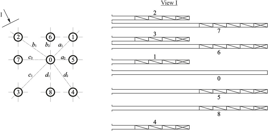
Figure 1. Sectional technique to form a cut cavity: 0: central compensatory borehole; 1–4: snubber boreholes of the first section; 5–8: snubber boreholes of the second section; a1, b1, c1, and d1: distances between the central compensatory blasthole and the first-section snubber boreholes; a2, b2, c2, and d2: distances between the central compensatory blasthole and the second-section snubber boreholes.
The physical essence of the proposed technique to form a cut cavity is as follows. Initially, boreholes of the first section are exploded and deliver their effect due to the uncharged collars of long boreholes. As a result, a compensatory cavity is shaped, improving the operation of the second-section boreholes. In addition, zones of intensive regrinding and fissuring occur within the bottom parts of the cavity resulting from the first-section boreholes. In such a way, the broken-up rock mass presses-in (stems) the uncharged share of the neighboring second-section boreholes. Stemming, made of the crushed rock mass, will be more efficient than other tamping types because the material differs in greater internal friction coefficient, density, mass, and strength.
The study of the proposed procedure of a cut-cavity formation was executed in two stages:
1- Physical modeling on equivalent materials to determine the feasibility of sectional blasting;
2- Experimental explosions within the Shalkiya and Belousovski lead and zinc fields in the Republic of Kazakhstan when driving mine workings and when breaking ore in stopes. Ore mining within the fields involves the chamber-and-pillar method and mining by means of overlying formation caving.
The following composition Is selected for physical modeling: 55% rosin, 25% sealing wax, and 20% lead concentrate. The model material strength characteristics at the adopted scale of 1:30 are as follows: ϭс = 3.7 МPа, ϭt = 1.5 МPа, and γ = 2.7 t/m3. The selected material is similar to in situ conditions in terms of failure behavior. A mercury fulminate–chlorate–explosive mixture (16% mercury fulminate, 55.5% Berthollet salt, and 28.5% antimonium) is used as an explosive in model experiments. However, it turned out to be very labor-intensive and difficult to produce physical models with different strengths and different sections of mine workings, so further experimental work was carried out only to determine the possibility of a sectional blasting.
There are two basic ore bodies within the Shalkiya field (i.e., the Upper body and the Lower one); they are sheet-like and of a lenticular shape. The mineralization is localized in carboniferous clayey siliceous-dolomitic rhythmites. The ores are characterized by rather simple mineral composition. Sphalerite, galenite, and pyrite are the main ore minerals; gray copper ore and arsenopyrite are auxiliary ones (Telkov et al., 2019). Mainly, source minerals are represented by carbonates (i.e., dolomite, and less often calcite) and quartz. Micaceous and clayey aggregates, feldspars, and carbonaceous matter are of minor significance. The occurrence depth of the ore bodies is 40–50–860 m; their average thickness is 7–13 m. Rock strength varies from 8 to 14 on the Protodyakonov scale.
Belousovski field belongs to the pyrite–polymetallic ore formations (Shatagin and Lotfi, 2011). Chalcopyrite, sphalerite, galenite, pyrite, and baryte are the key ore minerals. Bornite, chalcocite, pyrite, and silver are the main minerals in the copper–pyritic ores. The basic deposit #5 has been prospected at a depth of 1,300 m. The deposit width is 100–200 m, and its average thickness is about 9 m, achieving 14 m within bulge areas. The deposit dip is northeast; the south-eastern flank dips 10°–20°; the north-western flank is a steep pitch. Rock strength varies from 10 to 18 on the Protodyakonov scale.
The average coefficient of the blasthole use is 0.88 while driving permanent and development mine workings and during ore breaking.
Experimental explosions within the mentioned deposits were executed to drive mine workings and to break ore in stopes. In this vein, the second-section blasthole depth was 1.6–4.4 m, and the first-section blasthole depth was 0.8–2.8 m, depending upon the broken rock formation strength. The diameter of the boreholes varied from 40 to 44 mm. If possible, mine workings and stopes with varying sections and strengths were selected. The rock mass strength changed from 10 to 18, and sections of the development and pre-production mine workings, as well as stopes, varied from 5.7 m2 to 20 m2. If boreholes were up to 2.0 m depth, and the mine working had small sections, then a packaged explosive such as ammonite 6GW, which is waterproof and covered by gelatin , was charged. In other cases, the granulated Granulit-AS-8 explosives were applied with a firing agent of an SINV type. SINV-type explosives are produced by the manufacturer with a delay time of 0 to 10,000 μs. During the experimental explosions, the delay time between the snubber blastholes of the first and second sections was 1–2 s. SINV agents differ from the current electric detonators in operating time accuracy as well as in safe blasting. After the explosion and the bottomhole airing, the BUC was determined by direct measurement of the residual blasthole depth.
In the next section, we detail our key results and discuss the implications of our research. Through this work, we aim to contribute not only to the field of mining engineering but also to the broader discourse on sustainable energy solutions, emphasizing the potential for efficient underground mine workings to play a pivotal role in the future of energy storage.
3 Results and discussion
At the initial stage of the research, the first-section snubber blasthole depth was determined based on the second-section snubber blasthole depth. Then the distance between the compensatory blasthole and the first- and second-section boreholes was determined.
Figures 2, 3 present photographs showing the state of the bottomholes within the Shalkiya and Belousovski fields after various types of blasting operations. By studying the condition of the bottomholes in various deposits and after different blasting methods, we can better understand and improve the tunneling process, which ultimately contributes to more efficient mining operations.
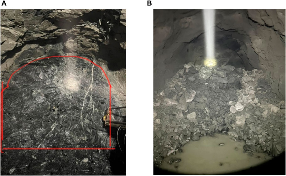
Figure 2. State of the bottomholes within the Shalkiya field: (A) After blasting the first-section snubber blastholes, and (B) after blasting the blastholes throughout the entire bottomhole.
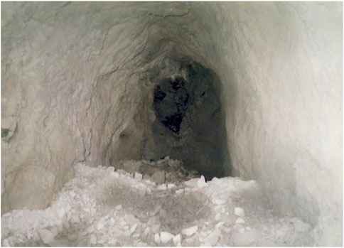
Figure 3. State of the bottomhole within the Belousovski field after blasting the snubber blastholes of the first and second sections.
Rock-forming minerals, when driving the drift, are represented mainly by carbonates (dolomite, less often calcite) and quartz. The rock strength is 10 on the Protodyakonov scale, and the bottomhole section is 8.4 m2. Figure 2A shows that after the explosion of the first-section snubber blastholes, only the mouths of the second-section snubber blastholes are visible, and the BUC of the first-section snubber blastholes is 1.
This explosion was executed in a mothballed cross-cut, driven through Paleozoic rocks, where the rock strength is 14 on the Protodyakonov scale, and the bottomhole section is 5.8 m2. Figure 3 shows that after the explosion of the snubber blastholes of the first and second sections, insignificant residual blasthole depths are visible, and the BUC is 0.98.
Table 1 demonstrates the results of the experiments. During the trial explosions, the strength of the broken rock formation varied from 10 to 18; consequently, the table involves the three categories of rock strength: 10–12, 12–14, and 16–18.
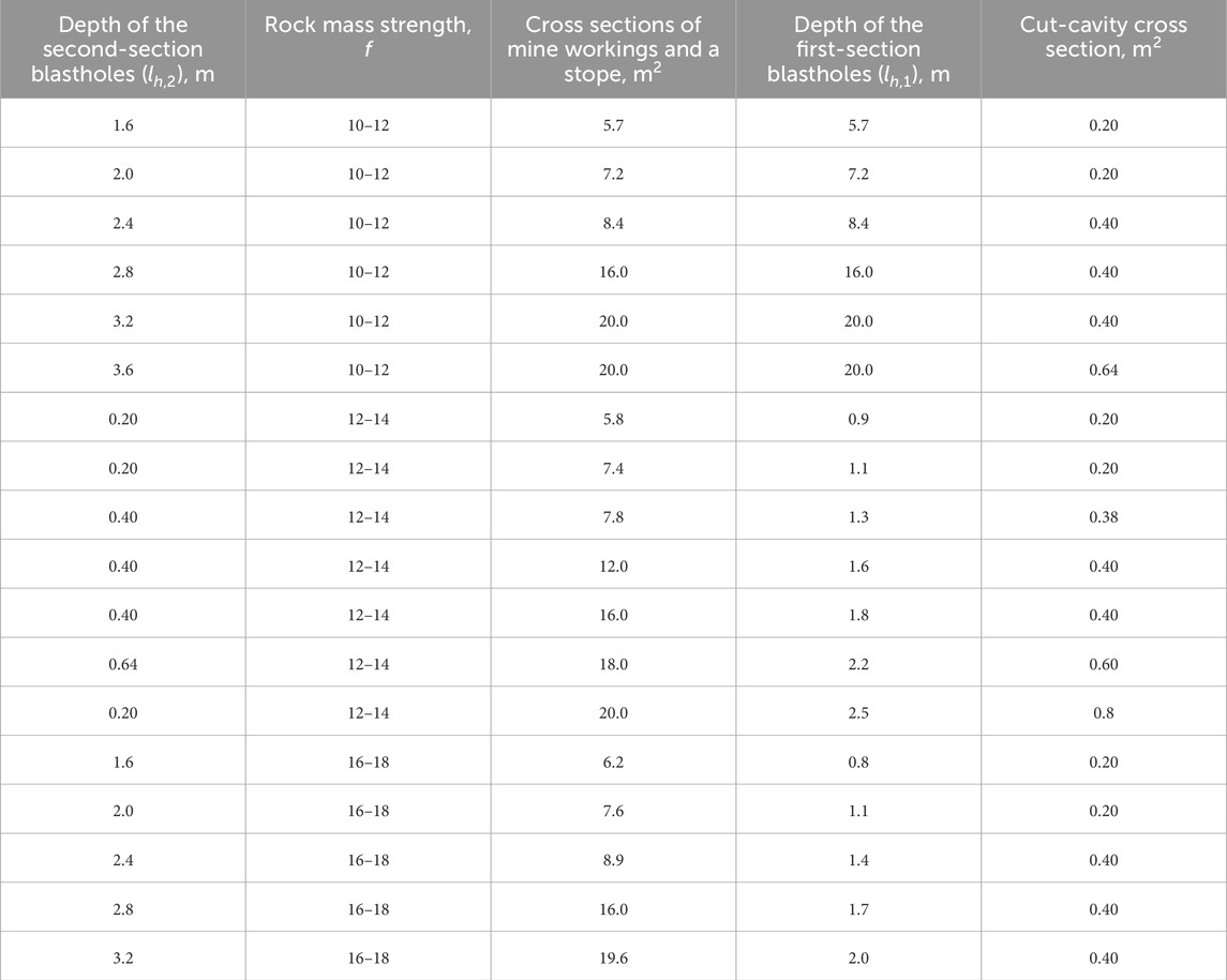
Table 1. Depth of the first-section boreholes and a cut-cavity cross section depending upon the rock mass strength and the second-section blasthole depth.
To identify the relationship between the first- and second-section blasthole depths, the trial explosions in a production environment were executed where possible at different blasthole depths as well as in broken rock of different strengths. The required depth of the first-section snubber blastholes based on the depth of the second-section blastholes was determined when the maximum value of the second-section BUC was reached by direct measurement after all snubber blastholes were exploded. After processing the experimental data (Table 1), the following empirical formulas were derived to identify the depth of first-section snubber boreholes relative to the depth of the second-section blastholes for different rock mass strengths:
Figure 4 explains the dependence of the first-section borehole depth on the depth of the second-section boreholes in terms of the different strengths of the broken rock mass.
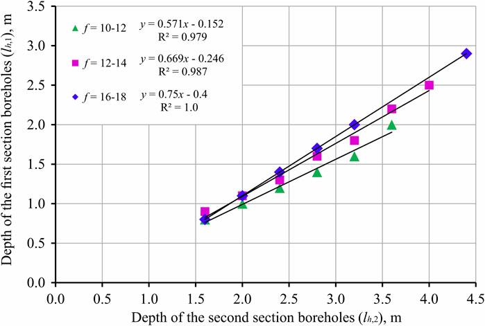
Figure 4. Dependence of the first-section snubber blasthole depth upon the depth of the second-section boreholes: y is the depth of the first-section boreholes (lh1), x is the depth of the second-section boreholes (lh2), and f is the strength of the rock formation.
The trial explosions showed that the first-section snubber borehole depth varies from 0.5 or more than that of the second-section boreholes, depending on the strength of the surrounding rock (Table 1). If the broken rock mass strength is 12, and the second-section blasthole length increases from 1.6 m to 2.8 m, then the first-section boreholes deepen from 0.9 m to 1.54 m, which is 55%–56% of the second-section blasthole length. The higher the strength of the broken rock mass is, the greater the ratio is between the first-section boreholes and the second-section boreholes.
Because snubber boreholes of the first and second sections differ in loading depth, cut efficiency should also involve optimum penetration intervals between the central compensatory boreholes and boreholes of the first and second sections.
To identify the distance between snubber boreholes and compensatory boreholes, trial explosions were executed in a production environment where both borehole diameters and rock strength varied. In this vein, distances from the central compensatory blasthole changed from 150 to 320 mm depending upon the succession of the hole firing. Each blast quality was inspected after its execution. Table 2 shows the obtained experimental penetration intervals.
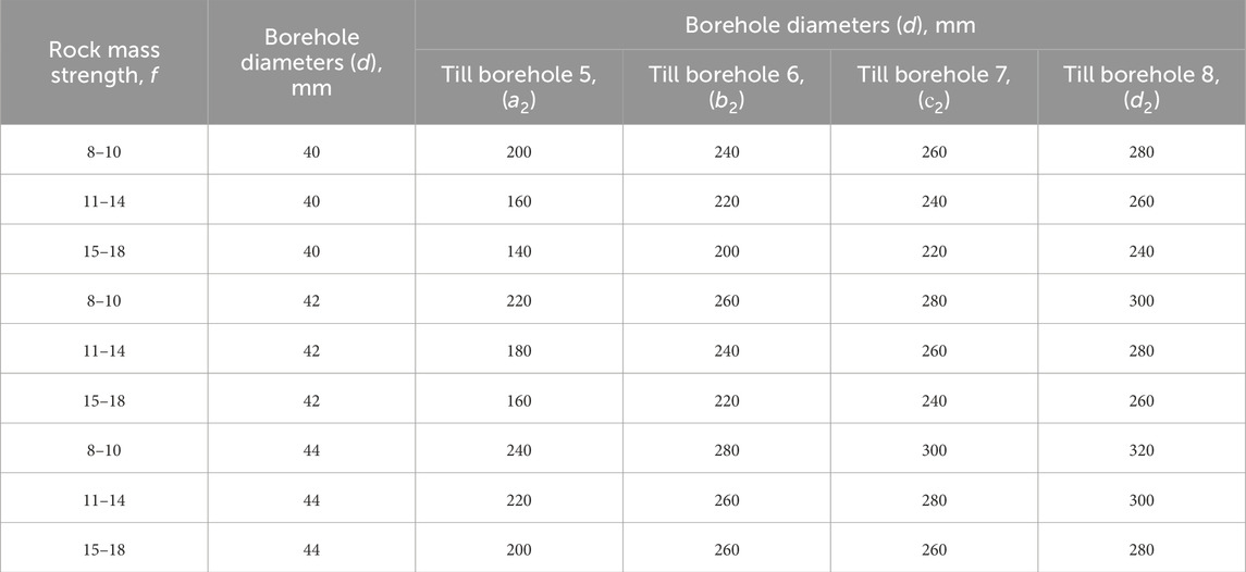
Table 2. Depth of the first-section boreholes and a cut-cavity cross section depending upon the rock mass strength and the second-section blasthole depth.
Mathematical processing of the data has made it possible to derive an empiric dependence defining the distance between the compensatory blasthole and second-section snubber boreholes for different rock mass strengths f = 8–10 (Eqs 2–5); f = 11–14 (Eqs 6–9); f = 15–18 (Eqs 10–13).
If the strength is f = 8–10 then
If the strength is f = 11–14, then
If the strength is f = 15–18, then
where dsh is blasthole diameter, m; and khe is the relative value of an explosive performance defined through a ratio between the perfect operation of the applied blasting agent and a sample one (Kabetenov et al., 2015).
The sample has been assumed to be 6 GW ammonite. The correlation coefficient was 0.96–0.99 for each of the obtained empiric dependencies.
The experiments have helped us understand that the optimum alternative in terms of blasthole use is one where collars of the first-section boreholes are arranged on the tops of a rectangle at distances from the central compensatory hole determined using the following formulas (14–17)
where a2, b2, c2, and d2 are defined through Eqs. (2)–(13).
After determining the parameters of the first- and second-section snubber blastholes, the parameters of the main boreholes must be identified. Experiments found that the value of a line of least resistance (LLR) varied within 0.3–0.7 m; a charge convergence coefficient varied within 0.45–2.57 m. The blasting results are shown in Table 3.
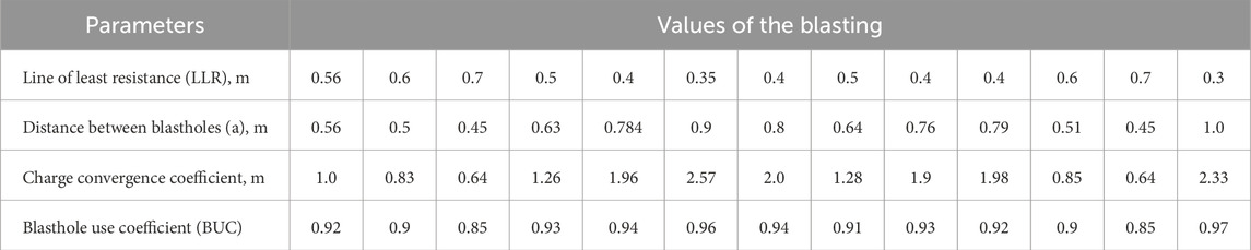
Table 3. Depth of the first-section boreholes and a cut-cavity cross section depending upon the rock mass strength and the second-section blasthole depth.
The BUCs and LLRs were determined based on the blasting results and depended on the distance between the blastholes (Figure 5).
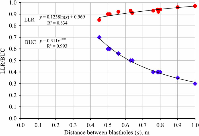
Figure 5. Dependence of the blasthole use coefficient and line of least resistance on the distance between boreholes.
As can be seen from the results of experimental activities, with the proposed technology of the cut-cavity formation and with a decrease in the LLR and an increase in the distance between blastholes, there is an increase in the BUC. For example, if the LLR value is 0.6 m and the distance between the blastholes is 0.5 m, the BUC is 0.9. When the LLR value is 0.35 m, and the distance between the blastholes is 0.9 m, the BUC is 0.95.
The cut-cavity formation procedure, when the depth of the first-section snubber blastholes is defined depending upon the second-section boreholes and on the broken rock strength, will improve the BUC to 0.96–0.97 if the parameters of the snubber and auxiliary blastholes and auxiliary are set correctly. Earlier studies assumed the depth of the first-section snubber boreholes was half that of the second-section snubber boreholes irrespective of the broken rock mass strength; moreover, the second-section snubber blastholes were charged the same as the auxiliary ones. There are no studies determining distances between the central compensatory boreholes and first- and second-section snubber blastholes. In such a case, the BUC achieved 0.95–0.96 depending upon the analyzed broken rock formation. In the proposed procedure for cut-cavity formation, the depth of the first-section blastholes is half or more of the depth of the second-section snubber boreholes according to the broken rock mass strength. In addition, formulas have been suggested to identify the distances between the central compensatory borehole and first- and second-section snubber blastholes depending upon the Boreholes diameter as well as the blasting agent efficiency.
The proposed technique for a cut-cavity formation using sectional cuts may be applied while driving underground workings and mining using chambers that have different cross sections. The procedure is applicable for varying rock strength when no traditional driving method is successful. The innovative technique of forming a cut cavity using sectional cuts is a significant breakthrough in the field of mineral extraction and underground construction.
The sectional cuts applied in this procedure help develop both accurate and stable cuts in rock masses varying in their strength and geological structure. This makes it possible to minimize caving risk while providing safety for miners. Moreover, the sectional cuts enable more efficient control over the geometry and shape of a mine, which may be extremely important while constructing underground chambers intended for different purposes.
Further studies for improving the efficiency of driving mine working while applying sectional cuts provide enormous potential to enhance both the effectiveness and use of the technique. Desk research can support pilot work defining the depth and parameters of first- and second-section snubber blastholes as well as auxiliary hole parameters depending upon the stress–strain state of the broken rock mass.
4 Conclusion
Trial blasts in a production environment have proved the efficiency of the proposed technique for the sectional formation of a cut cavity and helped increase the BUC from 0.88 to 0.97.
The depth of the first-section boreholes should be determined taking into consideration the second-section blasthole length as well as the broken rock formation strength; the higher the rock strength is, the greater the ratio between the lengths of the first- and second-section boreholes is.
Empiric dependencies have been derived for the distances between the central compensatory holes and the first- and second-section blastholes based on the borehole diameter and the efficiency coefficient of the blasting agent. In addition, a dependence of the BUC on an LLR and on the distance between the basic holes while using the sectional cuts has been identified.
New dependencies of the first-section borehole depth upon the second-section blasthole length have been determined for varying broken rock strengths and mine working cross sections. The higher the strength of the brokenrock mass is, the greater the ratio between the lengths of the first as well as the second-section boreholes is.
Data availability statement
The original contributions presented in the study are included in the article/Supplementary Material; further inquiries can be directed to the corresponding authors.
Author contributions
VL: conceptualization, funding acquisition, investigation, project administration, writing–original draft, and writing–review and editing. KY: conceptualization, funding acquisition, investigation, methodology, supervision, validation, visualization, and writing–original draft. KR: data curation, project administration, validation, and writing–review and editing. SR: formal analysis, methodology, validation, and writing–original draft. OB: funding acquisition, project administration, and writing–review and editing.
Funding
The author(s) declare that financial support was received for the research, authorship, and/or publication of this article. This study was carried out as part of the project “Belt and Road Initiative Center for Chinese-European Studies (BRICCES)” and was funded by the Guangdong University of Petrochemical Technology.
Acknowledgments
We would like to express our gratitude to the Committee on Science of the Ministry of Science and Higher Education of the Republic of Kazakhstan for providing Grant No. AP14871011, which made this research possible.
Conflict of interest
The authors declare that the research was conducted in the absence of any commercial or financial relationships that could be construed as a potential conflict of interest.
Publisher’s note
All claims expressed in this article are solely those of the authors and do not necessarily represent those of their affiliated organizations, or those of the publisher, the editors, and the reviewers. Any product that may be evaluated in this article, or claim that may be made by its manufacturer, is not guaranteed or endorsed by the publisher.
References
Aguirre-Unceta, R. (2023). Kazakhstan: extractive resources, governance and inclusive development. J. Econ. Soc. Dev, 1–23. doi:10.1007/s40847-023-00252-1
Atakhanova, Z., and Azhibay, S. (2023). Assessing economic sustainability of mining in Kazakhstan. Min. Econ. 36, 719–731. doi:10.1007/s13563-023-00387-x
Babets, D., Sdvyzhkova, O., Hapieiev, S., Shashenko, O., and Prykhodchenko, V. (2023). Multifactorial analysis of a gateroad stability at goaf interface during longwall coal mining–A case study. Min. Miner. Depos. 17, 9–19. doi:10.33271/mining17.02.009
Bazaluk, O., Anisimov, O., Saik, P., Lozynskyi, V., Akimov, O., and Hrytsenko, L. (2023a). Determining the safe distance for mining equipment operation when forming an internal dump in a deep open pit. Sustainability 15, 5912. doi:10.3390/su15075912
Bazaluk, O., Ashcheulova, O., Mamaikin, O., Khorolskyi, A., Lozynskyi, V., and Saik, P. (2022). Innovative activities in the sphere of mining process management. Front. Environ. Sci. 10, 878977. doi:10.3389/fenvs.2022.878977
Bazaluk, O., Kuchyn, O., Saik, P., Soltabayeva, S., Brui, H., Lozynskyi, V., et al. (2023b). Impact of ground surface subsidence caused by underground coal mining on natural gas pipeline. Sci. Rep. 13, 19327. doi:10.1038/s41598-023-46814-5
Bazaluk, O., Petlovanyi, M., Zubko, S., Lozynskyi, V., and Sai, K. (2021). Instability assessment of hanging wall rocks during underground mining of iron ores. Minerals 11, 858. doi:10.3390/min11080858
Bitimbayev, M. Z., Rysbekov, K. B., Krupnik, L. A., and Stolpovskikh, I. N. (2022). Patent №6903 Method of underground development of ore deposits using “bottom-up” approach. Patent Republic of Kazakhstan.
Bitimbayev, M.Zh., Yusupov, Kh.A., and Aben, E. (2023). Kh. Patent № 7854. Longline underground mining method. Patent Republic of Kazakhstan.
Bondarenko, V., Salieiev, I., Kovalevska, I., Chervatiuk, V., Malashkevych, D., Shyshov, M., et al. (2023). A new concept for complex mining of mineral raw material resources from DTEK coal mines based on sustainable development and ESG strategy. Min. Min. Depos. 17, 1–16. doi:10.33271/mining17.01.001
Cardu, M., Saltarin, S., Todaro, C., and Deangeli, C. (2021). Precision rock excavation: beyond controlled blasting and line drilling. Mining 1, 192–210. doi:10.3390/mining1020013
Cheng, B., Wang, H., Zong, Q., Wang, M., Gao, P., and Lv, N. (2022). Study on the improved method of wedge cutting blasting with center holes detonated subsequently. Energies 15 (12), 4282. doi:10.3390/en15124282
Cheng, J., Song, W., Jing, Y., Zhang, X., Korzec, M., Borowski, M., et al. (2020). Research on mine seal stability under explosion load and ground pressure in underground coal mines. Archives Min. Sci., 71–87. doi:10.24425/ams.2020.132707
Chlachula, J., Zhensikbayeva, N. Z., Yegorina, A. V., Kabdrakhmanova, N. K., Czerniawska, J., and Kumarbekuly, S. (2021). Territorial assessment of the east Kazakhstan geo/ecotourism: sustainable travel prospects in the southern altai area. Geosciences 11, 156. doi:10.3390/geosciences11040156
Egorov, A. P., and Kondakov, I. A. (2019). Evaluation of the possibility and effectiveness of the implementation of technological schemes for high-speed underground mining in coal mines. Ugol’ 10, 22–28. doi:10.18796/0041-5790-2019-10-22-28
Evgenievna, M. T., Ugli, T. A. A., and Abdurakhimovna, M. G. (2020). Prospects for ore flow quality management in deep pits. Int. J. Adv. Sci. Technol. 1, 31–35. doi:10.24412/2181-144X-2020-2-31-35
Gao, P., Zong, Q., Cheng, B., Wang, H., Xu, Y., and Zhang, B. (2022). Investigation on cutting blasting efficiency of hard rock tunnels under different charge diameters. Appl. Sci. 12 (19), 9906. doi:10.3390/app12199906
Ginatulin, A. M., Derbas, A. N., and Asanbaeva, U. T. (2019). Sostoyanie vospolneniya zapasov vedushchikh poleznykh iskopaemykh Respubliki Kazakhstan: problemy i nekotorye puti ikh resheniya. Almaty: Geologiya i okhrana nedr, 86–91.
Grabara, J., Tleppayev, A., Dabylova, M., Mihardjo, L. W. W., and Dacko-Pikiewicz, Z. (2021). Empirical research on the relationship amongst renewable energy consumption, economic growth and foreign direct investment in Kazakhstan and Uzbekistan. Energies 14, 332. doi:10.3390/en14020332
Hou, L., Elsworth, D., Wang, J., Zhou, J., and Zhang, F. (2024). Feasibility and prospects of symbiotic storage of CO2 and H2 in shale reservoirs. Renew. Sust. Energ. Rev. 189, 113878. doi:10.1016/j.rser.2023.113878
Hunt, J. D., Zakeri, B., Jurasz, J., Tong, W., Dąbek, P. B., Brandão, R., et al. (2023). Underground gravity energy storage: a solution for long-term energy storage. Energies 16, 825. doi:10.3390/en16020825
Hussan, B., Takhanov, D., Kuzmin, S., and Abdibaitov, S. (2021). Research into influence of drilling-and-blasting operations on the stability of the Kusmuryn open-pit sides in the Republic of Kazakhstan. Min. Miner. Depos. 15, 130–136. doi:10.33271/mining15.03.130
Kabetenov, T., Yusupov, K. A., and Rustemov, S. T. (2015). Rational parameters of blasting, considering action time of explosion-generated pulse. J. Min. Sci. 51, 261–266. doi:10.1134/S1062739115020076
Kongar-Syuryun, C. B., Aleksakhin, A. V., Eliseeva, E. N., Zhaglovskaya, A. V., Klyuev, R. V., and Petrusevich, D. A. (2023). Modern technologies providing a full cycle of geo-resources development. Resources 12, 50. doi:10.3390/resources12040050
Konicek, P., Soucek, K., Stas, L., and Singh, R. (2013). Long-hole destress blasting for rockburst control during deep underground coal mining. Int. J. Rock Mech. Min. Sci. 61, 141–153. doi:10.1016/j.ijrmms.2013.02.001
Kononenko, M., and Khomenko, O. (2010). “Technology of support of workings near to extraction chambers,” in New techniques and technologies in mining (London: CRC Press), 193–197. doi:10.1201/b11329-31
Kononenko, M., Khomenko, O., Kovalenko, I., Kosenko, A., Zahorodnii, R., and Dychkovskyi, R. (2023). Determining the performance of explosives for blasting management. Rud.-geol.-naft. zb 38, 19–28. doi:10.17794/rgn.2023.3.2
Kononov, I. P., Kunets, G. O., Lyash, S. I., and Lyash, I. S. (1999). Improvement of drilling and blasting operations during horizontal mining. Min. J. 4, 27–29.
Kurchin, G. S., Vokhmin, S. A., Kirsanov, A. K., Shigin, A. O., and Shigina, A. A. (2015). Calculation methodology of blasting and explosion operations' parameters for construction of horizontal and inclined excavations. Int. J. Appl. Eng. Res. 10 (15), 35897–35906.
Kutuzov, B. N. (2008). “Methods of blasting operations,” in Blasting operations in mining and industry (Moscow: Publishing House “Gornayakniga”), 512.
Li, C., Kang, Y., Zhang, Y., and Luo, H. (2021). Effect of double holes on crack propagation in PMMA plates under blasting load by caustics method. Theor. Appl. Fract. Mech. 116, 103103. doi:10.1016/j.tafmec.2021.103103
Li, C., Yang, R., Wang, Y., Kang, Y., and Zhang, Y. (2023b). Theory and numerical simulation of deep hole cut blasting based on dispersed charge and staged detonation. Int. J. Rock Mech. Min. Sci. 169, 105453. doi:10.1016/j.ijrmms.2023.105453
Li, C., Yang, R., Wang, Y., Kang, Y., Zhang, Y., and Xie, P. (2023c). Theoretical and numerical simulation investigation of deep hole dispersed charge cut blasting. Int. J. Coal Sci. Technol. 10 (1), 15. doi:10.1007/s40789-023-00571-y
Li, H., Ma, H., Zhao, K., Zhu, S., Yang, K., Zeng, Z., et al. (2023a). Parameter design of the compressed air energy storage salt cavern in highly impure rock salt formations. Energy 286, 129520. doi:10.1016/j.energy.2023.129520
Litvinenko, V. S. (2020). Digital economy as a factor in the technological development of the mineral sector. Nat. Resour. Res. 29, 1521–1541. doi:10.1007/s11053-019-09568-4
Liu, X., Tao, T., Tian, X., Lou, Q., and Xie, C. (2022). Layout method and numerical simulation study of reduced-hole blasting in large-section tunnels. Front. Earth Sci. 10, 976419. doi:10.3389/feart.2022.976419
Mazina, A., Syzdykova, D., Myrzhykbayeva, A., Raikhanova, G., and Nurgaliyeva, A. (2022). Impact of green fiscal policy on investment efficiency of renewable energy enterprises in Kazakhstan. Int. J. Energy Econ. Policy 12, 491–497. doi:10.32479/ijeep.13437
Mertuszka, P., Szumny, M., Fuławka, K., and Kondoł, P. (2022). Novel approach for the destress blasting in hard rock underground copper mines. J. Sustain. Min. 21, 141–154. doi:10.46873/2300-3960.1352
Mertuszka, P., Szumny, M., Fuławka, K., Maślej, J., and Saiang, D. (2019). The effect of the blasthole diameter on the detonation velocity of bulk emulsion explosive in the conditions of selected mining panel of the Rudna mine. Archives Min. Sci. 64 (4), 725–737. doi:10.24425/AMS.2019.131062
Myrzakhmet, M., and Begimbay, K. (2022). Inclusion of universities, enterprises, and regions of Kazakhstan in the process of technological upgrading of the mining industry: a triple helix approach. Int. J. Technol. Learn. Innov. Dev. 14, 78–107. doi:10.1504/IJTLID.2022.121480
Nehrii, S., Nehrii, T., Volkov, S., Zbykovskyy, Y., and Shvets, I. (2022). Operation complexity as one of the injury factors of coal miners . Min. Miner. Depos. 16, 95–102. doi:10.33271/mining16.02.095
Nikkhah, A., Vakylabad, A. B., Hassanzadeh, A., Niedoba, T., and Surowiak, A. (2022). An evaluation on the impact of ore fragmented by blasting on mining performance. Minerals 12, 258. doi:10.3390/min12020258
Pivnyak, G., Bondarenko, V., Kovalevs’ka, I., and Illiashov, M. (2012). Geomechanical processes during underground mining. London: CRC Press, 238. doi:10.1201/b13157
Pysmennyi, S., Chukharev, S., Peremetchy, A., Fedorenko, S., and Matsui, A. (2023). Study of stress concentration on the contour of underground mine workings. Inz. Min. 51, 69–78. doi:10.29227/IM-2023-01-08
Pysmennyi, S., Fedko, M., Chukharev, S., Rysbekov, K., Kyelgyenbai, K., and Anastasov, D. (2022). Technology for mining of complex-structured bodies of stable and unstable ores. IOP Conf. Ser. Earth Environ. Sci. 970, 012040. doi:10.1088/1755-1315/970/1/012040
Quigley, M., and Dimitrakopoulos, R. (2020). Incorporating geological and equipment performance uncertainty while optimising short-term mine production schedules. Int. J. Min. Reclam. Environ. 34, 362–383. doi:10.1080/17480930.2019.1658923
Rustemov, S. T. (2012). Improvement of mining operations and improvement of labor safety of tunnellers. Bul. Kyrgyz Slav. Univ. 12, 124–128.
Rysbekov, K. B., Bitimbayev, M. Z., Akhmetkanov, D. K., and Miletenko, N. A. (2022). Improvement and systematization of principles and process flows in mineral mining in the Republic of Kazakhstan. Eurasian Min. 1 (18), 41–46. doi:10.17580/em.2022.01.08
Rуsbekov, K., Bitimbayev, M., Akhmetkanov, D., Yelemessov, K., Barmenshinova, M., Toktarov, A., et al. (2022). Substantiation of mining systems for steeply dipping low-thickness ore bodies with controlled continuous stope extraction. Min. Min. Depos. 16, 64–72. doi:10.33271/mining16.02.064
Sarybayev, O., Nurpeisova, M., Kyrgizbayeva, G., and Toleyov, B. (2015). Rosk mass assessment for man-made disaster risk management. New Dev. Min. Eng., 403–409. doi:10.1201/b19901-70
Serdaliyev, Y., and Iskakov, Y. (2022). Research into electro-hydraulic blasting impact on ore masses to intensify the heap leaching process. Min. Min. Depos. 16, 52–57. doi:10.33271/mining16.01.052
Shakenov, A., Kramsakov, D., and Stolpovskih, I. (2023). Mining haul truck operation failure analysis. Eng. J. Satbayev Univ. 145, 32–35. doi:10.51301/ejsu.2023.i4.05
Shatagin, N. N., and Lotfi, B. A. (2011). Priznaki oprokinutogo zaleganiya chetvertoy zalezhi belousovskogo kolchedanno-polimetallicheskogo mestorozhdeniya, rudnyy altay. Rudy i Met. 6, 45–52.
Shirokiy, P. G., Zavaley, V. A., Auelkhan, Ye.S., and Alzhigitova, M. M. (2024). Review of methods for processing ore vanadium-containing raw materials. Eng. J. Satbayev Univ. 146 (1), 15–22. doi:10.51301/ejsu.2024.i1.03
Skrzypkowski, K., Gómez, R., Zagórski, K., Zagórska, A., and Gómez-Espina, R. (2023). Review of underground mining methods in world-class base metal deposits: experiences from Poland and Chile. Energies 16, 148. doi:10.3390/en16010148
Sokolov, I. V., Smirnov, A. A., and Rozhkov, A. A. (2017). Explosive breaking of quartz by concentrated charges in underground mining. Min. Inf. Anal. Bul. 10, 178–185. doi:10.25018/0236-1493-2017-10-0-178-185
Song, H., Zhu, S., Li, J., Wang, Z., Li, Q., and Ning, Z. (2023). Design criteria for the construction of energy storage salt cavern considering economic benefits and resource utilization. Sustainability 15, 6870. doi:10.3390/su15086870
Telkov, Sh.A., Motovilov, I.Yu., and Barmenshinova, M. B. (2019). Substantiation of gravity concentration to the shalkiya deposit lead-zinc ore. Fiziko-tekhnicheskie Probl. Razrab. Polezn. Iskop. 9, 99–105. doi:10.15372/FTPRPI20190312
Wróblewski, A., Wodecki, J., Trybała, P., and Zimroz, R. (2023). Large underground structures geometry evaluation based on point cloud data analysis. IOP Conf. Ser. Earth Environ. Sci. 1189 (1), 012005. doi:10.1088/1755-1315/1189/1/012005
Yang, C., Wang, T., and Chen, H. (2022). Theoretical and technological challenges of deep underground energy storage in China. Engineering 25, 168–181. doi:10.1016/j.eng.2022.06.021
Yıldız, T. D. (2022). How can the state rights be calculated by considering a high share of state right in mining operating costs in Turkey. Resour. Policy 75, 102509. doi:10.1016/j.resourpol.2021.102509
Yusupov, H. A., and Myrzakhmetov, S. S. (2006). Determination of the detonation transmission distance. Theor. Appl. Sci. Tech. J., 458–461.
Zeng, X., Zhang, X., Zhou, X., Duan, Y., and Chen, J. (2023). Prediction of tunnel blasting vibration velocity considering the influence of free surface. Appl. Sci. 13 (3), 1373. doi:10.3390/app13031373
Zhang, Z. X. (2016). Rock blasting in open cut and tunneling. Rock Fract. Blasting, 334–352. doi:10.1016/B978-0-12-802688-5.00017-8
Keywords: underground mine, cavity, mine working, strength, borehole, blasthole
Citation: Lozynskyi V, Yussupov K, Rysbekov K, Rustemov S and Bazaluk O (2024) Using sectional blasting to improve the efficiency of making cut cavities in underground mine workings. Front. Earth Sci. 12:1366901. doi: 10.3389/feart.2024.1366901
Received: 07 January 2024; Accepted: 25 March 2024;
Published: 24 April 2024.
Edited by:
Bin Gong, Brunel University London, United KingdomReviewed by:
Chengxiao Li, University of Science and Technology Beijing, ChinaVivek Kumar Himanshu, Central Institute of Mining and Fuel Research, India
Copyright © 2024 Lozynskyi, Yussupov, Rysbekov, Rustemov and Bazaluk. This is an open-access article distributed under the terms of the Creative Commons Attribution License (CC BY). The use, distribution or reproduction in other forums is permitted, provided the original author(s) and the copyright owner(s) are credited and that the original publication in this journal is cited, in accordance with accepted academic practice. No use, distribution or reproduction is permitted which does not comply with these terms.
*Correspondence: Vasyl Lozynskyi, bHZnLm5tdUBnbWFpbC5jb20=; Khalidilla Yussupov, ay55dXNzdXBvdkBzYXRiYXlldi51bml2ZXJzaXR5