 Xu Liang1
 Li Shi
- 1Hangzhou Urban Infrastructure Construction Management Center, Hangzhou, Zhejiang, China
- 2Power China Huadong Engineering Corporation Limited, Hangzhou, Zhejiang, China
- 3Zhejiang Huadong Engineering Construction and Management Corporation Limited, Hangzhou, Zhejiang, China
- 4College of Civil Engineering, Zhejiang University of Technology, Hangzhou, Zhejiang, China
- 5Zhejiang Engineering Research Center of Green Mine Technology and Intelligent Equipment, Hangzhou, Zhejiang, China
Existing studies on soil-pipe interaction due to tunneling mainly focus on short-term responses. However, in areas with high water tables and low permeability soil, long-term ground movement and associated pipe responses may occur due to dissipation of excess pore pressure generated during tunnel construction. In this paper, a Winkler solution with time-varying subgrade modulus and the corresponding greenfield soil displacement formula are developed to investigate the tunneling effects on existing pipelines. The pipe is considered as an infinite Euler beam of finite width resting on a poroelastic half-space, and adhesion and drainage effects between the pipe and soil are considered using bounding techniques. The greenfield consolidation settlement is evaluated using a modified Gaussian curve. The findings indicate that the subgrade modulus decreases while greenfield soil displacement increases during the consolidation process. The time-dependent behavior of the subgrade modulus is governed by the drainage condition at the pipe-soil interface, whereas the greenfield soil displacement is primarily influenced by the drainage condition at the tunnel-soil interface. The study reveals that the bonded contact condition, hydraulic boundary condition, and displacement constraint conditions all influence the bending moment of the pipe.
1 Introduction
The tunnel construction causes volume loss of soil, and the surrounding soil deforms into the gap between the tunnel wall and lining. Ground deformation causes soil settlement around nearby underground facilities, e.g., the existing pipelines. The pipe suffers deformation and bending moment when it is subjected to the soil settlement. To guide the design of protective measures on the pipelines, it is of vital importance to develop predictive methods to evaluate the tunneling effects on the existing pipelines.
The core of the problem at hand is the pipe-soil-tunnel interaction, of which a complete description generally requires a continuum-theory based model including the three objects at the same time. The most widely adopted approach should be the finite element method (FEM). By discretizing the pipeline and soil in to shell and solid elements, respectively, Klar and Marshall (2008) investigated the deformation of the pipeline when subjected to a nearby tunneling construction. Based on a similar modeling technique, Marshall et al. (2010) simulated the pipeline deformation caused by tunnel underpass and compared to the observed mechanical behavior from a centrifugal model test. Wang et al. (2011) conducted parameter analysis using finite element software and obtained the relationship between the normalized bending moment of the pipeline and the relative stiffness coefficient between the pipe and soil. However, the preparing of FEM model and mesh could be cumbersome especially at the design stage, which involves a lot of parametric studies. Meanwhile, the finite element method is less effective in identifying nondimensional parameters governing the pipe-soil-tunnel system. Alternatively, the existing studies on this problem generally decouple the pipe from tunnel by adopting relaxing assumptions, e.g., the pipe does not affect the tunnel when the tunneling-induced ground displacement happens (Mair et al., 2005); and the soil response to pipe loading at the pipe level is not aware of the tunnel (Vorster et al., 2005).
With the above assumptions, the problem was solved using a two-step method in the literature: i) obtain the ground displacement profile at the pipeline level (i.e., the so-called greenfield soil displacement); ii) solve the pipe soil interactions using the greenfield displacement as input.
At step i), only the tunnel and the ground are involved. The tunneling induced ground displacement was evaluated using either field observation method (Mair et al., 1993), Peck (1969) and Schmidt (1969), after processing a large amount of surface settlement data, believe that the cross-sectional surface settlement curve caused by tunnel excavation can also be represented by a Gaussian curve, analytical method (Loganathan and Poulos, 1998) or numerical method (Wongsaroj et al., 2013). Based on field observations, the tunneling-induced ground settlement is commonly fitted into empirical formulas, e.g., a Gaussian curve (Peck, 1969). However, in some cases the Gaussian curve is not satisfactory to accurately describe the soil settlement (Celestino et al., 2000). Later, the Gaussian curve was modified by Voster et al. (2005) and by Wei (2013) to admit more flexibility in adjusting the shape of the ground settlement profile. It is noted that the existing studies on the tunneling induced ground displacement are generally focused on the short-term response, which is caused by undrained shear deformation of soil happen immediately after the tunnel construction. In comparison, the long-term ground displacement would happen with the dissipation of excess pore water pressure induced by tunneling. Actually, when the pore water flows to the new drainage boundary imposed by the tunnel, the soil consolidates, and the consolidation of the soil leads to certain changes in the parameters of the soil, which in turn leads to continued settlement of the soil (Venkata Vydehi et al., 2022). Moreover, changes in the nature of the soil can have an effect on the consolidation of the soil (Moghal et al., 2020). It is demonstrated by Stallebrass et al. (2000) that the long-term settlement (i.e., by the seepage consolidation) can be 30% larger than the short term for soils of low permeability. In this paper, we will consider the soil settlement due to the seepage consolidation effect of the soil after shield excavation.
At step ii), the interaction problem between the pipe and soil is solved using the tunneling-induced soil displacement as inputs. The conventional approach for this problem is the Winkler-based models (Attewell et al., 1986), i.e., the pipe is governed by the Euler beam theory; and the soil is represented by a series of individual springs connected to the beam. If the soil is modeled as a continuum, this problem can be solved in a more rigorous manner, which leads to the elastic continuum solution developed by Vorster et al. (2005). Later, the continuum-based solution has been extended to include the effects of pipe joints (Klar et al., 2008) and elastoplastic behaviors (Klar et al., 2007) on the pipeline responses.
When the Winkler-based model is adopted, the appropriate spring coefficient (i.e., the subgrade stiffness) is of vital importance for the accurate prediction of pipeline responses. Attewell et al. (1986) suggested the use of Vesic (1961) equation for the subgrade modulus. After comparing to the elastic continuum solution, Klar et al. (2007) suggested a new equation for the subgrade modulus. By considering the embedding depth of pipes, Yu et al. (2013) proposed different equations for the subgrade modulus. It is noted that the existing equations for the subgrade modulus are obtained for the pipe (modeled as Euler beam) interacting with an elastic continuum (representing the soil). As a result, the subgrade modulus does not change with time (i.e., the pore water and seepage are not considered). However, as mentioned in the above, the soil would experience seepage consolidation, and thus the subgrade modulus is subjected to change with the consolidation process.
To sum up, the two-step method is commonly adopted to evaluate the tunneling effects on existing pipelines, in which both the greenfield soil displacement and the subgrade modulus are important intermediate results; however, they are generally evaluated for the short-term responses. Once the soil layer that the tunnel and pipelines are buried is of relatively low permeability, the seepage consolidation of soil after the tunnel construction would become important, and thus the time-dependent greenfield displacement and subgrade modulus should be considered.
In this paper, a Winkler solution with time-varying subgrade modulus and the greenfield soil displacement is developed to investigate the tunneling effects on existing pipelines. In evaluating the subgrade modulus, the pipe is treated as an infinite Euler beam of finite width resting on a poroelastic halfspace. The influence of adhesion and drainage effects between the pipe and soil is considered by bounding techniques for prescribing the boundary conditions on the interface. As for the tunneling-induced consolidation settlement, the evaluation method proposed by Laver et al. (2017) is followed. Based on the developed Winkler solution, the time-dependent bending moment responses of the existing pipeline induced by the tunneling can be evaluated.
2 Analysis model and assumptions
The tunneling induced deformation of the ground and pipeline is schematically shown in Figure 1. A new tunnel of diameter D is excavated under an existing pipeline of diameter d. The tunnel excavation generates soil displacement around the pipeline, which causes the pipe to deform and suffer bending moment. The burying depth of the pipe and tunnel (measured to the centerline) are denoted as
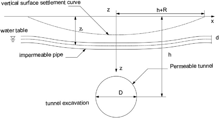
Figure 1. Schematic representation of tunneling effects on existing pipeline.
According to the two-step approach, the assumptions widely adopted in the literature are followed: a) the pipeline is continuous, and it is buried in a homogenous ground; b) the pipe is always in contact with the soil; c) the pipe does not affect the tunnel when the tunneling-induced ground displacement happens; d) the soil response to pipe loading at the pipe level is not aware of the tunnel.
Since the long-term responses of the tunnel-soil-pipe system are considered herein, additional assumptions are needed for the seepage consolidation analysis: e) the pipe does not affect the seepage-deformation coupled process of ground when the pore water flows to the new drainage boundary imposed by the tunnel; f) the seepage consolidation of soil to the pipe loading at the pipe level is not aware of the tunnel; g) the groundwater table is at the pipeline level, and thus the soil is fully saturated; h) the pipe is impermeable, and the tunnel is permeable. Essentially, assumptions e) and f) have the same physics with assumptions c) and d), respectively. In other words, if assumptions c) and d) are acceptable, assumptions e) and f) become valid automatically.
Based on assumptions c) and e), the consolidation displacement of ground can be evaluated without considering the pipe. While assumptions d) and f) allow the interaction analysis between the pipe and saturated soil without the tunnel. Thus, the tunneling effects on the existing pipe considering the seepage consolidation of ground can be analyzed by the classic two-step approach, which is elaborated in the following sections.
3 Winkler model of pipe-soil interaction analysis
The essentials of a Winkler model are an Euler beam of infinite length representing the pipe and a series of independent springs representing the soil. The governing equation of the Winkler model reads:
where EI is the bending stiffness of pipe;
By introducing
For an infinite Winkler beam, a concentrated load P induces a bending moment
The infinitesimal concentrated loads
The maximum bending moment in the pipe occurs above the tunnel centerline, referred to as the maximum sagging moment. According to Eqs 2–4 and by integrating the distribution of the infinitesimal concentrated loads, we can obtain the maximum bending moment:
4 Subgrade modulus
The knowledge of subgrade modulus K plays important in evaluating the pipeline responses. The Vesic equation (1961) is commonly adopted for the subgrade modulus, i.e.,
in which, E0 and v are the drained elastic modulus and Poisson’s ratio of soil, respectively. As indicated by Klar et al. (2007), the physical meaning of Eq. 6 is allowing a beam on Winkler foundation to exhibit similar displacements and moments to those of a beam on an elastic foundation when loaded with concentrated loads. In other words, the subgrade modulus is evaluated by referring to a beam resting on the surface of a halfspace.
In the literature the short-term settlement is routinely considered, and thus Eq. 6 is obtained for a beam on an elastic halfspace. The short-term settlement is caused by undrained shear deformation of the soil, which happens immediately in the tunnel construction process. However, when the seepage consolidation of soil is involved, the subgrade modulus becomes time-dependent (typically in soil layers of low permeability). Under this condition, the subgrade modulus should be evaluated by referring to a beam resting on a saturated poroelastic halfspace.
The analysis model of an infinite beam resting on the surface of a saturated poroelastic halfspace is shown in Figure 2. A rectangular section of width 2b (2b=d, d is the pipe diameter) is assigned to the beam. The beam experiences flexure only in the longitudinal direction (i.e., x axle), i.e., the beam section is infinitely rigid in the transverse direction (no flexure in the y-z plane).
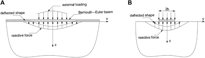
Figure 2. Analysis model of a beam resting on a saturated poroelastic half-space (after Selvadurai and Shi, 2015): (A) longitudinal view; (B) cross section view.
For convenience of presentation, the region of the surface of the halfspace in contact with the beam is denoted by:
4.1 Governing equations
The constitutive equations governing the seepage consolidation response of a poroelastic halfspace, which consists of an isotropic soil skeleton saturated with a compressible pore fluid, are expressed as
where p is the pore fluid pressure;
where
The equations governing the quasi-static fluid flow are defined by Darcy’s law, which takes the form
where
The basic Equations 7–12 are characterized by five independent material parameters which are the drained Poisson’s ratio, the undrained Poisson’s ratio
According to assumption h), boundary
As is evident, the poroelastic adhesive contact problem for the infinite beam on a poroelastic halfspace defined by Eq. 13 has to consider not only the mixed boundary conditions applicable to
Case A. considering the shear traction free and pervious boundary conditions prescribed over
Case B: considering the shear traction free and impervious boundary conditions prescribed over
Case C: considering the inextensibility and pervious boundary conditions prescribed over
Case D: considering the inextensibility and impervious boundary conditions prescribed over
4.2 Fundamental solutions of the poroelastic halfspace
For convenience, the beam half-width b, the shear modulus
are introduced to render all physical quantities non-dimensional as
In Eq. 19,
We adopt a method that involves the use of Fourier and Laplace transforms to obtain the fundamental solutions of the poroelastic halfspace. Adopting the relaxed boundary conditions (Eqs 14a–17d), the pipe-soil interaction analysis will become relatively easy. At the same time, the pipe-soil interaction solution under the strict boundary condition (Eq. 13a) should be within the range limited by the above four post-relaxation solutions. Details of the derivation can be found in the paper by Selvadurai and Shi (2015). The fundamental solutions of pore pressure, soil displacement and traction stresses are expressed in the transform domain, as shown in Supplementary Appendix SA1. The solutions are expressed as functions of
4.3 Evaluating subgrade modulus
The subgrade modulus in the transform domain can be expressed as
where the tidal and bar above the symbol denote variable in the transform domain. For the formulation of the subgrade modulus, the contact force
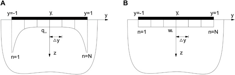
Figure 3. Discretization of contact boundary conditions over the beam-half space interface
As can be seen from Figure 3, the beam-halfspace interface is discretized into N strips with equal width
In Eq. 21,
where
After replacing the displacement compatibility condition in Cases A to D by Eq. 23 and combining the left boundary conditions in each case with Eq. 22, a set of algebraic equations can be formed in Fourier-Laplace transform domain to evaluate the subgrade modulus defined in Eq. 20. The details of derivation can be found in the paper by Shi and Selvadurai (2015). Take Case A as an example, the subgrade modulus can be obtained by solving
where
and its value (Eq. 25) in the spatial-temporal domain can be obtained by performing inverse Fourier-Laplace transformations.
5 Greenfield soil settlement
It is a common practice to describe the short-term greenfield soil settlement due to tunneling using a Gaussian curve. However, as reported by Vorster et al. (2005) the Gaussian curve is not satisfactory to accurately describe the soil settlement in many cases. Instead, they proposed a modified Gaussian curve of the following form
in which,
In Eq. 27, α is a parameter to ensure i remains the distance to the inflection point.
Following the same profile function, Wongsaroj et al. (2013) investigated the long-term settlement induced by the dissipation of the tunneling-generated excess pore water pressure towards the drainage boundaries. Later, Laver et al. (2017) extended the work of Wongsaroj et al. (2013), and proposed an empirical formula-based chart for evaluating the consolidation settlement for both transient and steady-state long-term conditions. Here, we follow the chart by Laver et al. (2017), and list the main steps as follows
Step (1), evaluate the dimensionless settlement DS, i.e.,
In Eq. 28, RP is a dimensionless parameter measuring the relative soil-lining permeability,
In Eq. 29,
Step (2), evaluate the steady state nondimensional settlement
In Eq. 30,
Step (3), evaluate the steady state nondimensional settlement
Step (4), according to Eq. 31, convert the nondimensional settlement to actual settlement, i.e.,
In Eq. 32,
Step (5), according to the actual steady-state settlement, find the transient settlement at required time,
In Eq. 33,
In Eq. 34,
Step (6), evaluate the transverse distribution of the transient settlement at required time (i.e., the ground settlement profile at particular time) according to the modified Gaussian curve. By replacing i in Eq. 26 by
In Eq. 36,
Step (7), evaluate the transient settlement profile at the pipeline level (i.e.,
In Eq. 38,
6 Verification
Since no results have been published on the consolidation effects on the pipe-soil interaction problem due to tunneling, the solution developed in this study will be simplified and then verified at elementary levels: (1) the subgrade modulus; and (2) the bending moment of pipeline subjected to short-term settlement caused by tunneling.
(1) Verification on subgrade modulus K. The analysis consider an infinite pipeline resting on a saturated homogeneous half-space is considered. The pipeline is of diameter d=2b=0.8 m, wall thickness dt=20 mm, and bending rigidity EI=1.3×10⁴ kN m2. The material parameters of the saturated soil are as follows: E0=40 MPa, ν=0.3, νu=0.5, k=5×10⁻⁸ m/s, μ=15.4 MPa, B=1, and γw=10 kN/m3.
As indicated in Figure 3, to establish a bonded contact condition between the pipeline and the soil, the contact area is discretized into multiple strips, ensuring a constant displacement of the pipeline across all sections. This contact condition can be simplified to the “average contact” condition when N=1, where the contact force
Using the aforementioned parameters, computational results for the subgrade modulus K are presented in Figure 4 for Cases A and B. The figure also includes the prediction from Vesic equation (Eq. 6). Initially, the soil exhibits fully undrained behavior governed by the undrained Poisson’s ratio vu. As consolidation occurs, the soil behavior gradually transitions to a fully drained state governed by the drained Poisson’s ratio v. As vu>v, the magnitude of the subgrade modulus decreases with the consolidation of the soil. The Vesic equation, based on the fully drained condition, within the scope of “average contact” (N=1) and “bonded contact” condition (N=20) calculations. The range calculated by “bonded contact” condition (N=20) is greater than “average contact” (N=1).
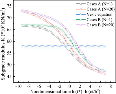
Figure 4. Verification on subgrade modulus K.
(2) Verification of bending moment of pipeline subjected to short-term settlement. Wei et al. (2009) studied the bending moment response of a pipeline, considering only the transient soil settlement induced by tunneling. The tunnel and pipeline axes have burying depth of h=5 m and z0=1.5 m, respectively. The pipeline is of diameter d=0.8 m, wall thickness dt=0.12 m, and bending rigidity EI=4.58×10⁵ kN m2. The tunnel, constructed in a homogenous elastic ground with elastic modulus E0=3.08 MPa and Poisson’s ratio
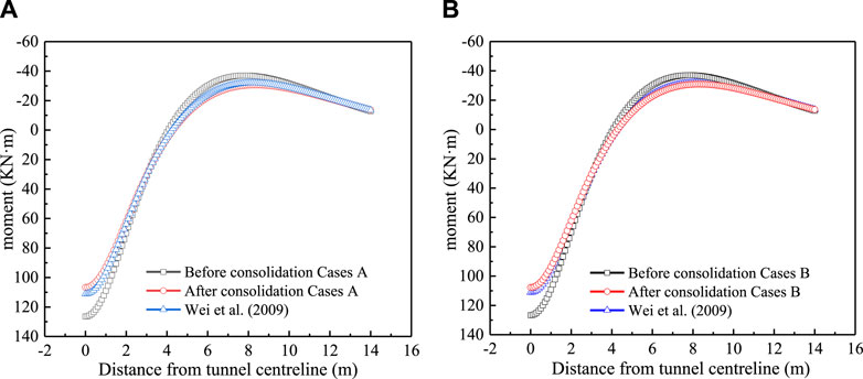
Figure 5. Verification on bending moment of pipeline subjected to transient short-term settlement: (A) Cases A; (B) Cases B.
By conducting thorough verification on the subgrade modulus and the bending moment of the pipeline subjected to short-term settlement, it is established a strong foundation for further investigation into the consolidation effects on the pipe-soil interaction problem due to tunneling.
7 Numerical results
By using the two-step method, the tunneling effects on an existing pipeline striking perpendicularly to an underpassing tunnel are investigated in this section. The burying depths of the tunnel and pipeline axes are h=10 m and z0=1 m, respectively. The tunnel of radius D=6 m is constructed in a homogenous saturated poroelastic ground. The tunnel lining is of thickness tt=0.2 m and permeability kt=1×10⁻⁹ m/s. The pipeline is of diameter d=2b=0.8 m, wall thickness dt=20 mm and bending rigidity EI=1.3×10⁴ kN m2. Material parameters of the saturated soil are E0=40 MPa, ν=0.3, νu=0.5, k=5×10⁻⁸ m/s, μ=15.4 MPa, B=1 and γw=10 kN/m3. As stated in Section 5, the volume loss of soil induced by tunneling is VL=1.5%.
With the above parameters, the following intermediate parameters can be evaluated: the thickness of soil between the tunnel crown level and the water table CS=6 m; the relative soil-lining permeability RP=23.1; the dimensionless settlement DS=0.54; the distance to the inflection point of the greenfield settlement trough profile i=10.65; the consolidation coefficients governing the tunnel-soil and pipeline-soil interactions are ct=2×10⁻⁴ and c= 2.15×10⁻⁶, respectively.
7.1 Subgrade modulus
With the above-listed parameters, the subgrade modulus K resulting from the pipeline-soil interaction can be evaluated by using the method provided in Section 4. Figure 6 presents the time-dependent subgrade modulus under the four boundary conditions (i.e., Cases A∼D). A decrease in the subgrade modulus can be observed for all the four boundary conditions (i.e., Cases A∼D) with the elapsing consolidation time. Initially (t*→0), the soil behaviors fully undrained, and the soil is volumetrically incompressible due to νu =0.5. Thus, the subgrade modulus K is of the same magnitude between Cases A∼D. With the seepage consolidation of soil, it is seen that the subgrade modulus associated with Cases B and D is higher than that associated with Cases A and C. The difference is due to the hydraulic boundary condition at the ground surface. In Cases B and D, the surface is impervious, which implies that the excess pore water pressure can only be dissipated into the infinity of ground. In comparison, the surface is pervious in Cases A and C, and the water can flow freely out of the surface. Then, it is understood that K of Cases B and D is large since the water flow (of nearly zero compressibility) is constrained. When the time approaches the end of consolidation, the subgrade moduli of Cases A and B (and similarly Cases C and D) converge to a same limiting value. It is seen that the limiting K (t*→∞) of Cases C and D is higher than that of Cases A and B. The explanation is that an inextensible ground surface (Cases C and D) would render a stiffer support to the pipeline when compared to the ground of frictionless surface (Cases A and B).
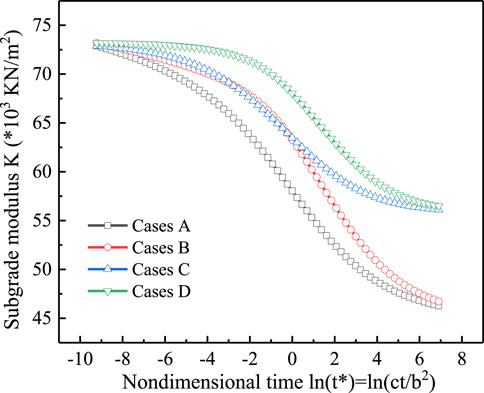
Figure 6. The variation of subgrade modulus with the seepage consolidation of soil.
To facilitate the comparison, the magnitude of subgrade modulus K is summarized in Table 1 for the beginning and end of the seepage consolidation, respectively. Also included in Table 1 is the prediction by Vesic equation, which is well bounded by the subgrade modulus associated with the four boundary conditions (Cases A∼D).

Table 1. Comparisons on subgrade modulus K between Cases A∼D.
7.2 Greenfield soil settlement
According to the steps listed in Section 5, the long-term settlement induced by the dissipation of the tunneling-induced excess pore water pressure can be obtained. It is noted that the short-term settlement caused by undrained shear deformation of soil during the tunnel construction is not considered. For the point of pipeline that is right above the tunnel, its greenfield settlement gradually increases with the seepage consolidation process, as shown in Figure 7. At initial stage of the seepage consolidation, the gain in settlement is marginal, which is due to the relatively large drainage distance Cs. Then, the consolidation settlement develops quickly before it reaches a stable value at the end of the consolidation (i.e., ln (t*) =6). The steady-state long-term settlement reads 11 mm.
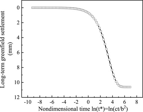
Figure 7. Long-term greenfield settlement for the point of pipeline (x = 0) that is right above the tunnel.
When the seepage consolidation is completed, the distribution of the steady-state settlement along the pipeline is shown in Figure 8. It is seen that the largest steady-state settlement happens right above the tunnel (i.e., x=0). With the horizontal distance away from the tunnel, the settlement decreases, which forms a typical trough profile covering a range x=0–50 m. From the figure, the distance to the inflection point of the settlement trough profile is 25 m.
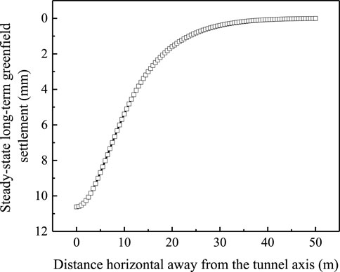
Figure 8. Distribution of steady-state long-term settlement along the pipeline.
7.3 Bending moment of pipeline
With the subgrade modulus K and greenfield soil settlement at the pipeline level Uz being determined in Sections 7.2, 7.3, respectively, the bending moment response of the pipeline can be evaluated by using the equations detailed in Section 3. The development of the maximum sagging moment (i.e., the bending moment in the pipe right above the tunnel centerline) (Eq. 5) with the nondimensional time ln (t*) is shown in Figure 9. The develop pattern of the maximum sagging moment resembles that of the greenfield settlement (see Figure 8), i.e., the increasing of bending moment is extremely slow before ln (t*) =0, after which the bending moment gains until the time ln (t*) =5. The curves associated with the four boundary conditions (Cases A∼D) basically overlap before the time ln (t*) =2, even though obvious difference between the subgrade moduli of the four cases exist (see Figure 7). This observation implies that the bending moment response of the pipeline is governed by the greenfield settlement input, especially during the initial and middle stages of the seepage consolidation. Towards the end of the consolidation, the maximum sagging moment associated with Cases A and B is about 10% larger than that with Cases C and D, which agrees with the finding that the pipe with stiffer subgrade would suffer smaller bending moment (Zhang and Huang, 2012).
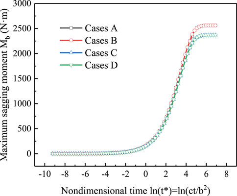
Figure 9. The development of maximum sagging moment of pipe with seepage consolidation.
As consolidation proceeds, the subgrade modulus decreases and the soil settlement increases. The pipe bending moment is affected by the soil settlement input and gradually increase, and its law of change with time is consistent with the law of change of soil settlement with time.
Since the bending moment develops quickly when the nondimensional time ln (t*)>2, the distributions of bending moment along the pipeline are presented in Figure 10 for three selected time instants, i.e., t*=10, t*=100, and t*=1,000. It is seen that the maximum sagging moment (of positive value) happens right above the tunnel (i.e., x=0 m), and the maximum hogging moment (of negative value) occurs near the edge of the settlement trough (i.e., x≈12 m). The maximum sagging and hogging moments of the pipeline associated with the four boundary conditions are summarized in Tables 2, 3, respectively. The exact value of maximum bending moment of the pipeline subjected to tunneling should fall within the bounds provided by Cases A∼D. Take the sagging moment as an example, its exact value at the steady state (i.e., t*=1,000) should be within the range (2370 N m, 2559 N m), whose upper and lower bounds are provided by Cases C and Case A, respectively. It is noted that this range is narrow enough for an engineering judge on the failure of pipeline.
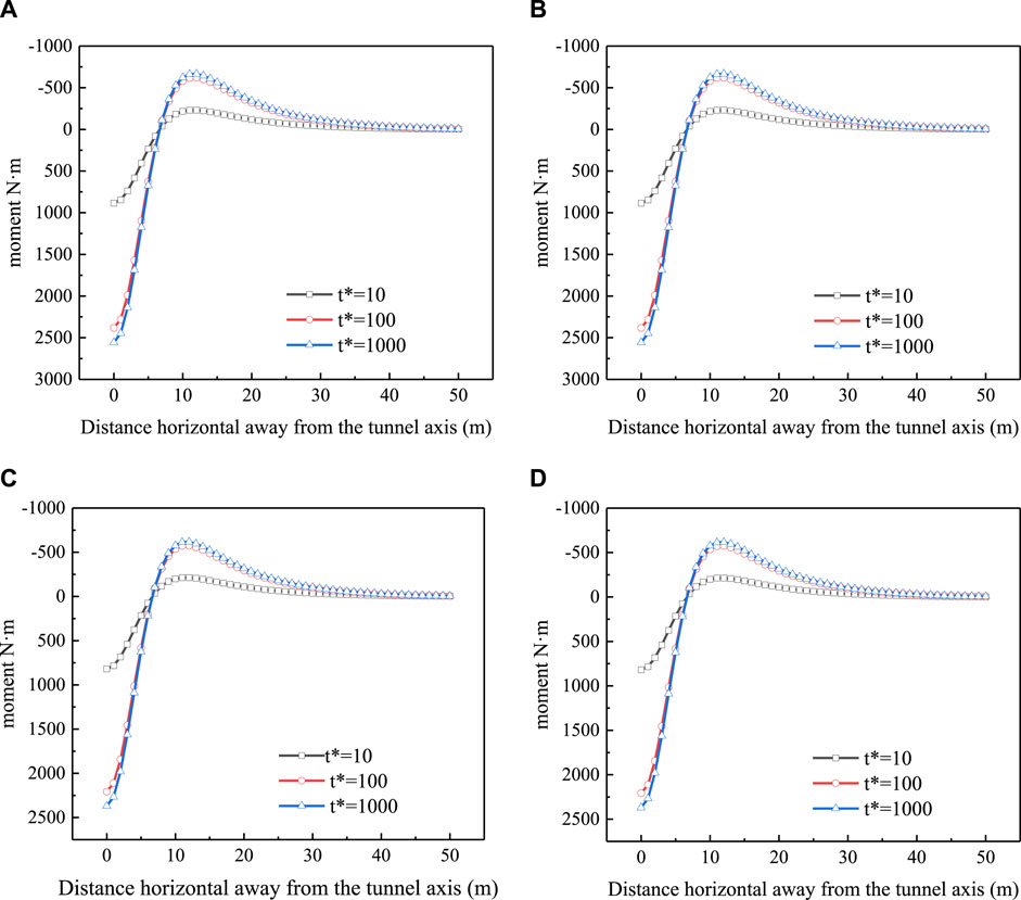
Figure 10. Distribution of bending moment along the pipeline at time instants t*=10, 100 and 1,000: (A) Case A; (B) Case B; (C) Case C; (D) Case D.
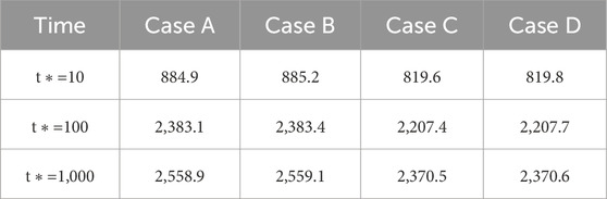
Table 2. The maximum sagging moment of the pipeline associated with the four boundary conditions.
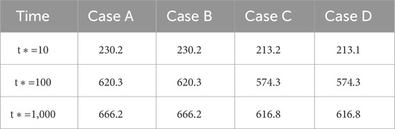
Table 3. The maximum hogging moment of the pipeline associated with the four boundary conditions.
7.4 Influence of permeability of tunnel lining
As indicated by Wongsaroj et al. (2013), the consolidation settlement by tunneling can be significantly influenced by the permeability of tunnel lining. Here, we consider four permeability of lining, i.e., kt=10−7 m/s, 10−8 m/s, 10−9 m/s and 10−10 m/s, respectively. The other parameters of the soil, pipe and tunnel are the same as those depicted at the beginning of Section 7. Take Case A as an example, the comparison on the maximum sagging moment is presented in Figure 11. It is seen that the increase of bending moment with time follows the same pattern between the four permeabilities, i.e., the bending moment increases slowly initially (ln (t*) <0), and then it grows quickly with time before it reaches a stable value around ln (t*) =5. The steady-state value of sagging moment increases with the increasing permeability. For example, the steady-state sagging moment associated with kt=10−7 m/s is about 8 times that with kt=10−10 m/s.
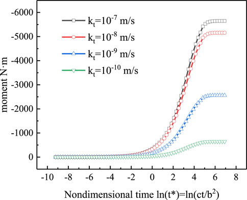
Figure 11. Development of maximum sagging moment with seepage consolidation under four permeabilities of tunnel lining.
When the seepage consolidation is completed, the distribution of bending moment along the pipeline is presented in Figure 12. Similar to the sagging moment, it is observed that the maximum hogging moment also increase with the increasing permeability of lining. For example, the hogging moment associated with kt=10−7 m/s is about 6 times that with kt=10−10 m/s.
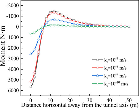
Figure 12. Distribution of bending moment along the pipeline under four permeabilities of tunnel lining.
8 Conclusion
To overcome the deficiency that only transient response can be considered in the analysis of the pipeline force caused by shield excavation, the pipe-soil contact stiffness is first derived taking into account the seepage consolidation effect of soft soil. Using the “two-step method”, the deformation field resulting from seepage consolidation in the adjacent layer due to shield excavation is input to develop an analytical prediction method for the force exerted on the adjacent pipeline. This approach takes full account of the effects of seepage consolidation in soft ground. The following conclusions are drawn:
(1) The subgrade modulus K decreases gradually with seepage consolidation. Initially, the subgrade modulus K is the same for the four boundary conditions. As the soil consolidates, the subgrade modulus associated with Case B and Case D are higher than that associated with Case A and Case C. This is because the surface is impervious in Cases B and D and pervious in Cases A and C. When the time approaches the end of consolidation, the subgrade moduli of Cases A and B (and similarly Cases C and D) converge to a same limiting value. It is seen that the limiting K (t*→∞) of Cases C and D is higher than that of Cases A and B. The explanation is that an inextensible ground surface (Cases C and D) would render a stiffer support to the pipeline when compared to the ground of frictionless surface (Cases A and B).
(2) The greenfield settlement increases gradually during the consolidation process, with slow development in the early stage, and accelerated growth in the middle stage.
(3) The development pattern of the maximum sagging moment mirrors that of the greenfield settlement. The increase in bending moment is initially slow, accelerates during the middle stage, and eventually stabilizes. Under four boundary conditions investigated, the difference between the final stable maximum and minimum bending moment is 10%.
(4) The steady-state value of sagging moment increases with increasing permeability. Specifically, the steady-state sagging moment associated with a larger permeability of lining kt would be higher than that associated with a lower kt.
Data availability statement
The original contributions presented in the study are included in the article/Supplementary Material, further inquiries can be directed to the corresponding author.
Author contributions
XL: Conceptualization, validation, formal analysis, writing–original draft. JX: Conceptualization, formal analysis, data curation. YH: methodology, validation, writing–original draft. LS: writing–original draft, data curation, writing–review and editing. ZZ: methodology, writing–original draft, data curation. BM: writing–original draft, data curation, writing–review and editing. LH: Conceptualization, formal analysis. JW: methodology, data curation, writing–review and editing.
Funding
The author(s) declare that financial support was received for the research, authorship, and/or publication of this article. This research was supported by Zhejiang Province Construction Research Projects (2023K155).
Conflict of interest
Authors YH, ZZ, LH, and JW were employed by Power China Huadong Engineering Corporation Limited. Authors YH and ZZ were employed by Zhejiang Huadong Engineering Construction and Management Corporation Limited.
The remaining authors declare that the research was conducted in the absence of any commercial or financial relationships that could be construed as a potential conflict of interest.
Publisher’s note
All claims expressed in this article are solely those of the authors and do not necessarily represent those of their affiliated organizations, or those of the publisher, the editors and the reviewers. Any product that may be evaluated in this article, or claim that may be made by its manufacturer, is not guaranteed or endorsed by the publisher.
Supplementary material
The Supplementary Material for this article can be found online at: https://www.frontiersin.org/articles/10.3389/feart.2024.1403663/full#supplementary-material
References
Attewell, P. B. (1981). Engineering contract, site investigation and surface movements in tunnelling works.
Attewell, P. B., Yeates, J., and Selby, A. R. (1986). Soil movements induced by tunnelling and their effects on pipelines and structures. new york ny: methuen inc.
Biot, M. A. (1941). General theory of three-dimensional consolidation. J. Appl. Phys. 12, 155–164. doi:10.1063/1.1712886
Celestino, T. B., Gomes, R. A. M., and Bortolucci, A. A. (2000). Errors in ground distortions due to settlement trough adjustment. Tunneling Undergr. Space Technol. 15 (1), 97–100. doi:10.1016/s0886-7798(99)00054-1
Klar, A., and Marshall, A. M. (2008). Shell versus beam representation of pipes in the evaluation of tunneling effects on pipelines. Tunn. Undergr. Space Technol. Incorporating Trenchless Technol. Res. 23 (4), 431–437. doi:10.1016/j.tust.2007.07.003
Klar, A., Marshall, A. M., Soga, K., and Mair, R. J. (2008). Tunneling effects on jointed pipelines. Can. Geotechnical J. 45, 131–139. doi:10.1139/t07-068
Klar, A., Voster, T. E. B., Soga, K., and Mair, R. J. (2007). Elastoplastic solution for soil-pipe-tunnel interaction. J. Geotechnical Geoenvironmental Eng. 133 (7), 782–792. doi:10.1061/(asce)1090-0241(2007)133:7(782)
Laver, R. G., Li, Z. L., and Soga, K. (2017). Method to evaluate the long-term surface movements by Tunneling in London clay. J. Geotechnical Geoenvironmental Eng. 143 (3), 06016023. doi:10.1061/(asce)gt.1943-5606.0001611
Loganathan, N., and Poulos, H. G. (1998). Analytical prediction for tunneling-induced ground movements in clays. J. Geotechnical Geoenvironmental Eng. 124 (9), 846–856. doi:10.1061/(asce)1090-0241(1998)124:9(846)
Mair, R. J., Soga, K., Klar, A., and Vorster, T. E. B. (2005). Soil-pipe interaction due to tunnelling: comparison between winkler and elastic continuum solutions. Geotechnique 55 (6), 461–466. doi:10.1680/geot.2005.55.6.461
Mair, R. J., Taylor, R. N., and Bracegirdle, A. (1993). Subsurface settlement profiles above tunnels in clays. Geotechnique 43 (2), 315–320. doi:10.1680/geot.1993.43.2.315
Marshall, A. M., Elkayam, I., and Klar, A. (2010). Centrifuge and discrete element modelling of tunnelling effects on pipelines.
Moghal, A. A. B., Vydehi, V., Moghal, M. B., Almatrudi, R., AlMajed, A., and Al-Shamrani, M. A. (2020). Effect of calcium-based derivatives on consolidation, strength, and lime-leachability behavior of expansive soil. J. Mater. Civ. Eng. 32 (4), 04020048. doi:10.1061/(asce)mt.1943-5533.0003088
Peck, R. B. (1969). Deep excavation and tunneling in soft ground. 7th Int. Cof. Soil Mech. Found. Eng. State Arts Volume.
Selvadurai, A. P. S., and Shi, L. (2015). Biot’s problem for a Biot material. Int. J. Eng. Sci. 97, 133–147. doi:10.1016/j.ijengsci.2015.09.004
Stallebrass, S. E., Jovicic, V., and Taylor, R. N. (2000). “Short term and long-term settlements around a tunnel in stiff clay,” in Numerical methods in geotechnical engineering.
Venkata Vydehi, K., Moghal, A. A. B., and Basha, B. M. (2022). Reliability-based design optimization of biopolymer-amended soil as an alternative landfill liner material. J. Hazard. Toxic, Radioact. Waste 26 (3), 04022011. doi:10.1061/(asce)hz.2153-5515.0000697
Vesic, A. B. (1961). Bending of beams resting on isotropic elastic solid. J. Eng. Mech. Div. 87, 35–53. ASCE. doi:10.1061/jmcea3.0000212
Vorster, T. E., Klar, A., Soga, K., and Mair, R. J. (2005). Estimating the effects of tunneling on existing pipelines. J. Geotechnical Geoenvironmental Eng. 131 (11), 1399–1410. doi:10.1061/(asce)1090-0241(2005)131:11(1399)
Wang, Y., Shi, J. W., and Ng, C. W. W. (2011). Numerical modeling of tunneling effect on buried pipelines. Can. Geotechnical J. 48 (7), 1125–1137. doi:10.1139/t11-024
Wei, G. (2013). Prediction of ground deformation induced by double parallel shield tunneling. Disaster Adv. 6 (13), 91–98.
Wongsaroj, J., Soga, K., and Mair, R. J. (2013). Tunnelling-induced consolidation settlements in London Clay. Geotechnique 63 (13), 1103–1115. doi:10.1680/geot.12.p.126
Yu, J., Zhang, C. R., and Huang, M. S. (2013). Soil-pipe interaction due to tunnelling: assessment of Winkler modulus for underground pipelines. Comput. Geotechnics 50, 17–28. doi:10.1016/j.compgeo.2012.12.005
Zhang, Z., and Huang, M. (2012). Boundary element model for analysis of the mechanical behavior of existing pipelines subjected to tunneling-induced deformations. Comput. Geotechnics 46 (Nov), 93–103. doi:10.1016/j.compgeo.2012.06.001
Glossary
Keywords: seepage consolidation, winkler solution, tunneling effects, existing pipelines, bending moment
Citation: Liang X, Xu J, Huang Y, Shi L, Zeng Z, Miao B, Huang L and Wu J (2024) Consolidation effects on pipe-soil interaction due to tunneling. Front. Earth Sci. 12:1403663. doi: 10.3389/feart.2024.1403663
Received: 19 March 2024; Accepted: 29 April 2024;
Published: 21 May 2024.
Edited by:
Xiaoyu Bai, Qingdao University of Technology, ChinaReviewed by:
Hong Zheng, Chinese Academy of Sciences (CAS), ChinaArif Ali Baig Moghal, National Institute of Technology Warangal, India
Copyright © 2024 Liang, Xu, Huang, Shi, Zeng, Miao, Huang and Wu. This is an open-access article distributed under the terms of the Creative Commons Attribution License (CC BY). The use, distribution or reproduction in other forums is permitted, provided the original author(s) and the copyright owner(s) are credited and that the original publication in this journal is cited, in accordance with accepted academic practice. No use, distribution or reproduction is permitted which does not comply with these terms.
*Correspondence: Li Shi, bGlzaGlAemp1dC5lZHUuY24=