 Minglei Kang1
 Wenjia Ma
- 1Yubei Water Conservancy Project Management Bureau of Henan Province, Jiyuan, China
- 2College of Geosciences and Engineering, North China University of Water Resources and Electric Power, Zhengzhou, China
- 3State Key Laboratory of Shield Machine and Boring Technology, Zhengzhou, China
As a critical component in achieving the rock-breaking function during the operation of Tunnel Boring Machines (TBM), the cutterhead inevitably generates significant vibrations during the rock-breaking process. These vibrations can lead to localized damage to the cutterhead and cause the abnormal failure of key components, which, in turn, may compromise the overall tunneling efficiency of the machine. This study investigates the load and vibration characteristics of the cutterhead during the rock-breaking process, employing large-scale physical model experiments conducted at varying cutter spacings. Real-time acceleration data from the cutterhead can be obtained through the monitoring system integrated into the TBM (Tunnel Boring Machine) experimental platform. The whole time-domain curves are stepped and periodic, as demonstrated by the test results. During excavation, the monitoring curves vibrate suddenly if the cutter-head becomes stuck or if rocks begin to fracture. The cutter-head primarily exhibits vibrations in the 0∼3 Hz range, characteristic of low-frequency oscillations. To obtain the real-time mechanical properties of the cutter-head, transient dynamic analysis was employed, utilizing the collected data as driving parameters. According to numerical simulation results, the vibration pattern during excavation is the superposition of random vibrations generated by rock breaking and the unloading of the tunnel face. Moreover, it is important to monitor the wear of the edge cutters throughout the boring operation in real-world construction scenarios. To prevent and control cutterhead vibration, it is recommended that the cutter spacing be as small as possible during the tunneling process. At a smaller tool spacing, the cutterhead will exhibit higher structural integrity, which may lead to a delay in the response of mechanical vibration. The conclusions presented offer valuable insights for the study of the mechanical properties and stability design of TBM cutterheads.
1 Introduction
The escalating pace of transportation network development has elevated the significance of Tunnel Boring Machines (TBM) in tunnel excavation endeavors, attributable to their inherent safety and operational convenience (Armaghani et al., 2017; Gong et al., 2006; Farrokh, 2021). Among the integral components of the TBM, the cutterhead assumes paramount importance. The cutterhead is a key component to realize the rock breaking function during TBM construction. When the disc cutter group breaks the rock, the cutterhead will inevitably produce strong vibration (Zhou et al., 2019; Zhou et al., 2018a; Zhou et al., 2018b). If vibration is not effectively controlled, it may lead to a range of engineering issues, including bearing seal failure and, in extreme cases, cutterhead fracture (Huo et al., 2015; Huo et al., 2017). Following the determination of the tunnel section, the selection of cutter spacing becomes a critical factor influencing both rock-breaking efficiency and cutterhead vibration. Examining the vibration and load characteristics of the cutterhead at different cutter spacings can yield valuable insights for practical construction applications (Lin et al., 2019; Wang et al., 2019).
At present, the existing research mainly focuses on the corresponding mechanism of rock when TBM passes through complex geological conditions and the derivation and verification of the optimal cutter spacing formula or numerical simulation analysis (Zhou P. et al., 2019; Han et al., 2017; Xiao et al., 2017). Due to the limitation of test conditions, there is still a big gap between the current rock breaking test and the actual situation of tunnel construction (Zhou et al., 2018c; Tan et al., 2015). This paper innovatively combines the cutterhead load characteristics with the cutterhead vibration caused by cutterhead rock breaking, and realizes the combination of physical modeling experiment and transient dynamic analysis. By adding a real-time monitoring system on the test bench, the three-dimensional acceleration data of the cutterhead under different cutter spacing can be accurately obtained, and the measured data are close to the actual construction state (Zhang et al., 2021).
The experimental platform used in this study for TBM boring modal experiments primarily consists of a rotary mechanism, an associated control system, a screw conveyor, tunneling apparatus, and a hydraulic pump station, as illustrated in Figure 1. This experimental platform is capable of conducting various rock-breaking tests on different rock samples under both vertical and horizontal conditions, including different tool materials, tool spacing arrangement and rock breaking cutting speed changes. This paper studies the physical model tests of rock breaking under various cutter spacings, which stands as one of the scarce scientific research endeavors capable of pioneering advancements in TBM’s indoor model testing.
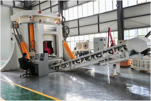
Figure 1. The TBM tunneling mode comprehensive experimental platform.
2 The setting of different cutter spacing and wireless sensor arrangement
The hob in the shield construction modal system is a standard 17-inch hob, with a diameter of 432 mm. The disc cutter consists of a cutter shaft, cutter body, and cutter ring. The primary objective of the simulation is to determine the load and vibration characteristics of the cutter ring during the rock-breaking process. To simplify the model, the cutter is represented as a hollow thin ring, retaining only the cutter ring and cutter body. In this simplified model, the cutter ring is positioned on the outer side and the cutter body on the inner side, as shown in Figure 2. Both the cutter ring and cutter body are assumed to be linear elastic and isotropic materials, with a density of 7,800 kg/m³, an elastic modulus of 2.1 × 10¹¹ Pa, and a Poisson’s ratio of 0.3. The cutter body is treated as a rigid body, with displacement restricted in directions outside the cutting plane.
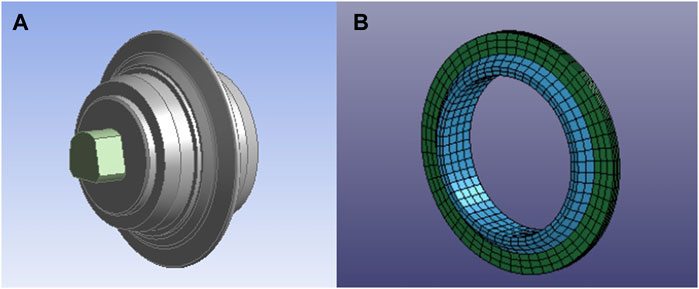
Figure 2. Standard disc cutter structure diagram. (A) Standard hob schematic diagram (B) Simplified model of standard disc cutter.
The tunnel boring machine (TBM) shield construction modal system developed by the State Key Laboratory of Shield and Tunneling Technology incorporates 14 built-in hobs, which include 6 central hobs and 8 positive hobs. Each central hob consists of 6 single-edged hob wedges mounted along a tool axis, while the positive hobs are arranged around the central hob, resulting in a total of 13 hob trajectory lines. The CAD drawing and the ANSYS three-dimensional diagram of the cutterhead are presented in Figure 3.
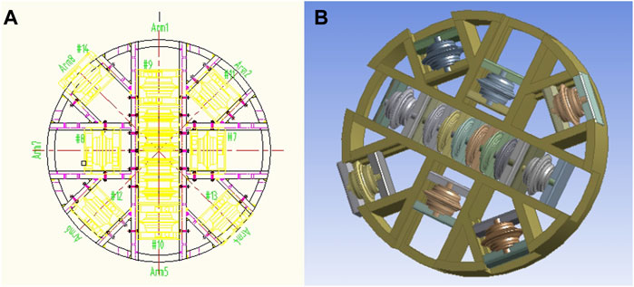
Figure 3. Cutterhead CAD drawings and three-dimensional schematics. (A) CAD drawing of cutter head (B) Three-dimensional diagram of the cutter head.
To simplify the simulation model and reduce computational time, the cutterhead cutting model of the test bench is reduced to two basic sub-models. The cutting model for the central disc cutter group is represented by six disc cutters, which are used to cut the disc-shaped rock. The cutting model for the positive disc cutter is simulated using cutters #7, #8, #9, and #10. These cutters are characterized by a smaller cutting radius, and their relative positioning is considered representative of typical cutter arrangements. The cutting surface of the rock is modeled as an annular shape, which reduces computational effort while ensuring that the trajectory of the disc cutters can be monitored in real-time. The hob cutting model is illustrated in Figure 4.
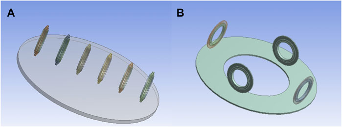
Figure 4. Hob cutting model diagram. (A) Center disc cutter cutting model (B) Cutting model of positive hob.
Based on the cutter-head of the TBM tunneling mode comprehensive experimental platform, a total of three typical cutter spacings are selected (Tan et al., 2016), involving 80 mm, 90 mm and 100 mm. The numerical simulation model corresponding to the three cutter spacings is shown in Figure 5.
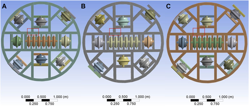
Figure 5. The setting of different cutter spacing. (A) 80 mm cutter spacing (B) 90 mm cutter spacing (C) 100 mm cutter spacing.
Expanding upon the existing TBM tunneling modal comprehensive test bench, a new system for testing has been incorporated. This system includes a wireless acceleration sensor, securely attached to the cutter head using a magnet. The wireless gateway receives the test data obtained by the sensor, and transmits it to the processing software after analysis and conversion to realize data forwarding, as shown in Figure 6. The arrangement position of the acceleration sensor on the cutterhead frame is determined by static analysis, the detailed method used is summarized in the reference (Wang et al., 2017). Notably, the sensor placement remains consistent across different cutter spacings.
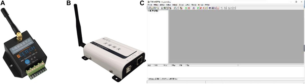
Figure 6. Test system flow chart. (A) The wireless acceleration sensor (B) Wireless gateway (C) The processing software.
3 Results
3.1 Data analysis under different cutter spacings
Following a month curing period with cement mortar, the uniaxial compressive strength of the rock plate was measured to be 32 MPa by the rebound instrument. The cutter-head operates at a speed of 1 r/min, with an advancement rate of approximately 20 mm/min. A sensor, positioned on the cutterhead, is capable of monitoring acceleration in three directions: x, y, and z. In this study, the x-direction corresponds to the cutter-head’s horizontal plane, the y-direction to its vertical plane, while the z-direction corresponds to the direction of tunneling. The experiment encompasses 4 distinct working conditions: tunneling without load, tunneling with 80 mm cutter spacing, tunneling with a cutter spacing of 90 mm, and tunneling with a cutter spacing of 100 mm. Time-domain curves and spectrum analyses for each cutter spacing are presented in Figure 7, while the characteristic values of the collected data are presented in Table 1. Notably, the cutter spacings have minimal effect on the cutterhead acceleration in the absence of load, prompting the presentation of a representative set of curves in this paper, as depicted in Figure 7A.
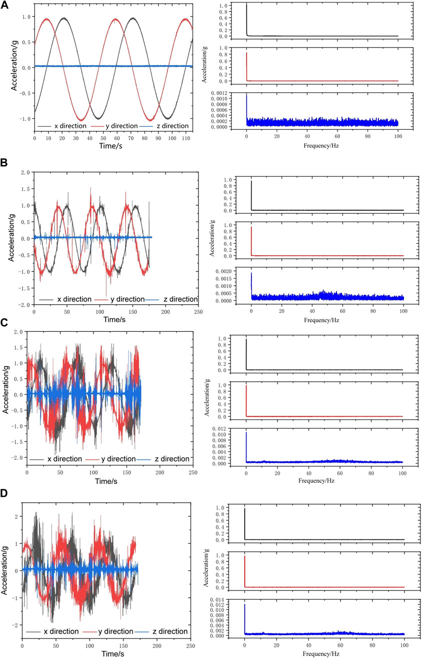
Figure 7. Measured time-domain curves and spectrum analysis of different conditions. (A) Original vibration without cutting. (B) 80 mm cutter spacing. (C) 90 mm cutter spacing. (D) 100 mm cutter spacing.
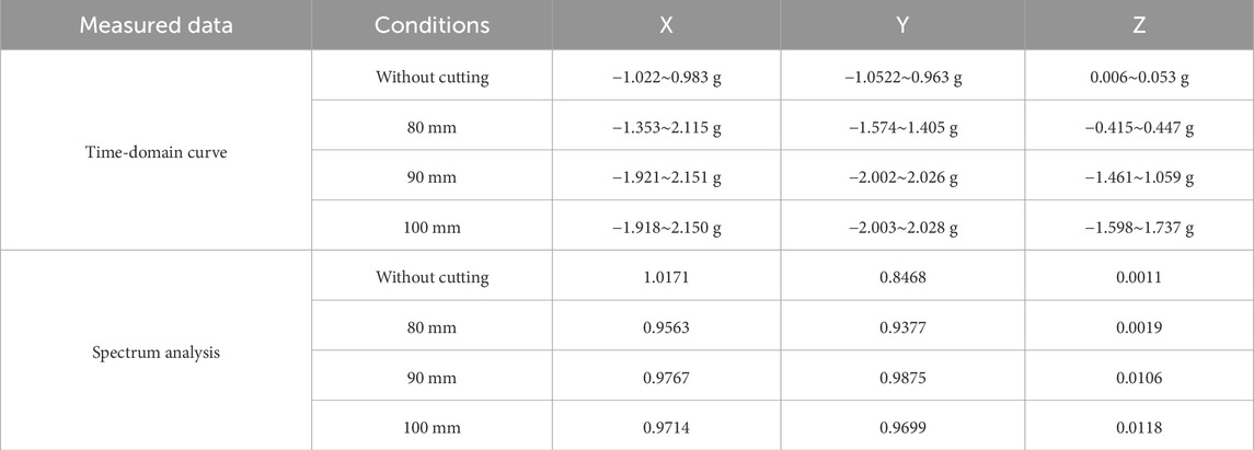
Table 1. The characteristic values of measured data.
Under the condition of tunneling without load, observations reveal cyclic reciprocation of acceleration in both the x and y directions, oscillating between −1 g and 1 g. The acceleration profiles of the cutter-head in these axes manifest sinusoidal or cosine patterns, with no significant vibrations or abrupt fluctuations. Since the z direction is parallel to the central axis of the tunnel, it remains approximately linear. Due to the limitation of the structure, the sensor cannot be concentrated inside the cutterhead, and the acceleration in the z direction is always kept near zero, and the fluctuation is small. In contrast to the monitoring curves of the unloaded cutter-head, acceleration curves exhibit abrupt vibrational spikes during rock-cutting operations. This experimental finding suggests that when the cutter-head becomes stuck or the rock breaks, vibrations appear in the time-domain curves.
Regarding the variation in acceleration magnitude, larger cutter spacings are associated with more pronounced vibrations. Specifically, the vibration amplitude in the x and y directions under different cutter spacings is 1.48–2.03 times greater than that observed during unloaded cutting. Significant differences in the vibration of the cutterhead are observed at different cutter spacings. As the cutter spacing increases to 80 mm, 90 mm, and 100 mm, the vibration amplitude of the cutterhead also increases. Specifically, the vibration amplitude at these spacings is 15.12, 44.17, and 58.56 times greater than that observed under no-load conditions, respectively. This phenomenon occurs due to the rotational movement of the cutter head masking some of the surface vibrations. Notably, vibrations in the tunneling direction offer a clearer depiction of the cutter-head’s dynamic characteristics without requiring additional processing.
The time-domain curves were analyzed using Fast Fourier Transform (FFT) to obtain their spectral characteristics. The vibration of the cutter head predominantly occurs within the 0–3 Hz range, indicating low-frequency vibrations. Although the cutter spacing has little effect on the vibration frequency, there are significant differences in the peak values of the cutter spacing of 80 mm, 90 mm and 100 mm, and the peak value of the spectrum gradually increases with the increase of the cutter spacing. Similar to the time domain curves, this tendency is more noticeable in the tunneling direction. Under 80 mm, 90 mm, and 100 mm cutter spacings, the FFT peak values of the cutter-head are 1.73 times, 9.63 times, and 10.73 times without load, respectively.
3.2 Dynamic analysis of cutter-head
To gain a deeper understanding of the cutter head’s load characteristics during tunneling, the measured data were used as input parameters for conducting transient dynamic analysis. Following the formulation of the mathematical model, the transient dynamics module of ANSYS software was employed to simulate the dynamic response of the cutter head. The equation governing the structural dynamics is given in Equation 1:
Within this formula, x1(t) represents the node acceleration vector, while x2(t) denotes the node velocity vector. The mass matrix and damping matrix are represented by M and K, respectively. The stiffness matrix and nodal load components are represented by C and q(t), respectively. Integration of the parameters described above is achieved by utilizing their corresponding unit matrices and vectors, which are given in Equations 2, 3.
Without taking the damping effect into account, the structural dynamic equation may be reduced to the form of Equation 4:
A method for assessing a structure or system’s dynamic reaction to a particular load over time is called transient dynamic analysis.
Based on the different attributes of the system, the transient dynamic analysis can be divided into two different orders of system analysis. According to this classification, second-order system analysis is a system with a second-order state that changes with time. For example, in structural analysis, the mass matrix is used to describe the distribution of mass in the structure and its influence on dynamic behavior. Because it involves the second derivative of displacement, structural analysis is considered to be a second-order system.
Transient structural dynamics analysis is a sub-field of structural dynamics analysis, which focuses on the analysis of the response of the structure to dynamic loads in a short time. Consequently, the general equation for transient analysis of second-order systems is given in Equation 5:
The real-time mechanical properties of the cutterhead are obtained by using the measured data for transient dynamic analysis, as shown in Figure 8. The measured data selected include time-domain curves representing a period under different tool spacings, and the measured curve of the cutter head of the uncut rock is used as a comparison. In the whole numerical simulation process, the fixed support is implemented in the rear section of the cutterhead, and the dynamic load is applied to other parts of the cutterhead.
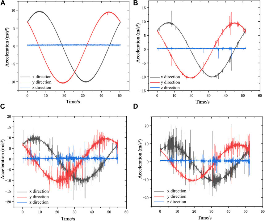
Figure 8. Utilized data for numerical simulation. (A) Initial vibration without any cutting. (B) 80 mm cutter spacing of rolling cutter. (C) 90 mm cutter spacing of rolling cutter. (D) 100 mm cutter spacing of rolling cutter.
Figure 9 presents the dynamic solution of real-time deformation and stress-strain for the cutter head. Subsequently, the mechanical properties of the cutter-head are detailed in Table 2 after organizing the data.
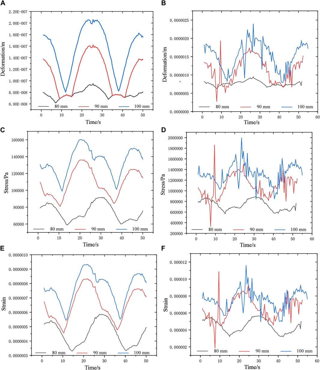
Figure 9. The time-domain curves of mechanical characteristics. (A) The max-deformation under no load. (B) The max-deformation with load. (C) The max-stress under no load. (D) The max-stress with load. (E) The max-strain without load. (F) The max-strain with load.
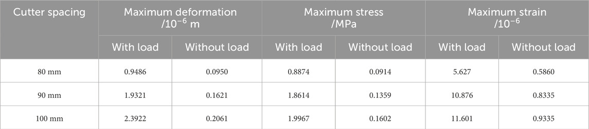
Table 2. The mechanical characteristics of cutter-head with different cutter spacings.
Compared with the cutter-head’s mechanical characteristics for rock-breaking, the changing amplitude of deformation and stress-strain without load are more gradual. Changes in the relative positioning of cutter spacing result in noticeable disparities in the mechanical characteristics of the cutter-head. An increase in the distance between cutters leads to a dispersal of the cutter head’s integrity, thereby expanding the influence of vibration load on its mechanical properties. Consequently, deformation and stress-strain within the cutter-head escalate as cutter spacing increases. At a cutter spacing of 100 mm, the highest measurements are recorded, whereas the lowest values are noted at a spacing of 80 mm. The structural discrepancies induced by cutter spacing are intensified during tunneling operations, resulting in noticeable variations in the cutter head’s mechanical condition. Specifically, in the absence of load on the cutter head, the deformation, stress, and strain values at a 90 mm cutter spacing are found to be 1.70, 1.48, and 1.42 times greater than those at an 80 mm spacing. Meanwhile, at a 100 mm cutter spacing, these values are 1.27, 1.75, and 1.11 times the corresponding measurements at the 90 mm spacing. When the cutters engage in rock breaking, the deformation, strain, and stress of the cutter head at 90 mm spacing are 2.03, 2.09, and 1.93 times those observed at an 80 mm spacing. For a 100 mm cutter spacing, these figures become 1.23, 1.07, and 1.06 times those measured at 90 mm spacing.
Moreover, the stochastic nature of vibrations can lead to abrupt alterations in the mechanical attributes of the cutter-head at particular locations, potentially surpassing existing thresholds. For instance, with a cutter spacing of 90 mm, an irregular amplitude is observed in the cutter-head during the rock-breaking operation, particularly around the 9-second mark. Obviously, the mechanical state of the cutterhead at this moment exceeds the corresponding value observed when the cutter spacing is 100 mm. Due to the complexity of geological conditions, this phenomenon is likely to occur frequently in the actual construction process.
4 Discussion
The mechanical distribution of the cutterhead in the limit state is compared, as shown in Figure 10. In terms of the deformation distribution of the cutter head, the position of the edge hob usually shows the maximum deformation. The deformation of the edge hob increases with the increase of the distance from the center of the cutterhead. Under the condition of no load, the deformation of the cutterhead is the largest under different cutter spacing, and the recorded value is 25.501 s. This instant represents not only the point where the time domain curves for the transverse and longitudinal directions intersect, but also the moment corresponding to the maximum value of the superimposed acceleration. During tunneling operations, the stochastic nature of vibration results in variable moment of maximum deformation across different cutter spacings. However, the maximum deformation occurs at the moment when the superimposed acceleration reaches the maximum.
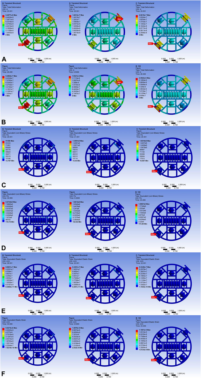
Figure 10. The dynamic analysis of the cutter head at 80 mm, 90 mm and 100 mm cutter spacing. (A) The max-deformation distribution under no load. (B) The max-deformation distribution with rock cutting. (C) The max-stress distribution under no load. (D) The max-stress distribution with load. (E) The max-strain distribution under no load. (F) The max-strain distribution with load.
There is a significant discrepancy in the cutter-head’s stress, strain, and deformation. The edge cutter located at the bottom left is where all study circumstances’ largest stress-strain is focused. When the cutterhead rotates at high speed, the centrifugal force increases with the increase of the distance from the rotation center. The centrifugal force of the edge disc cutter is larger, and the cutting force and axial force of the edge disc cutter are larger. Especially in the working state, the bending stiffness of the edge of the cutterhead is smaller, which makes the deformation of the edge part more obvious. At the same time, due to the vibration characteristics of the cutterhead, the edge part is far away from the rotation axis, the inertial force is large, and the response to the vibration is more intense, which in turn aggravates the deformation of the area. In the actual construction, attention should be paid to the wear of the cutting edge tool during the whole tunneling process. Additionally, under identical dynamic loads, the moment of maximum stress-strain for a cutter spacing of 80 mm occurs later compared to the other two operational conditions. This discrepancy can be attributed to the structural characteristics of the cutter-head. With the 80 mm cutter spacing, the cutter-head exhibits higher structural integrity, potentially resulting in a delayed response to mechanical vibrations.
When linked with the cutter-head’s time-domain curves, it becomes apparent that the vibration trend observed during excavation results from the superposition of random oscillations caused by the cutter shattering rock and tunneling without load. The dynamic state of tunneling can be predicted using the cutter-head’s mechanical properties while it is not under load. The reasoning is obtained under controllable test conditions, which provides an early warning basis for tool maintenance and replacement, and provides an optimization direction for cutter head design. By adjusting the tool spacing and optimizing the structure of the cutterhead, the negative impact of vibration on the cutterhead can be effectively reduced, thereby improving the stability and efficiency of the overall rock breaking operation.
5 Conclusion
This research employs large-scale physical model experiments to investigate the load characteristics of the cutterhead at varying cutter spacings. Utilizing the acquired data as input parameters, a transient dynamic analysis is conducted to determine the real-time load distribution on the cutterhead. By integrating experimental data with numerical simulations, the study draws the following conclusions:
1. The complete time-domain curve exhibits distinct step-like characteristics and periodic fluctuations. The vibration monitoring curves display sudden and sharp fluctuations when the rock peeled away or the cutter head became caught during rotation; the magnitude of this quick shift may have exceeded the threshold. In actual construction, particular attention should be given to the wear of the cutting edge too during the boring process. The time-domain curves were subjected to spectral analysis using the Fast Fourier Transform (FFT) method. The vibration of the cutterhead is predominantly concentrated in the 0–3 Hz range, indicating significant low-frequency vibration characteristics.
2. As the distance between the cutters increases, the structural integrity of the cutterhead is compromised, leading to an increased impact of vibration loads on its mechanical characteristics. When the cutterhead is in the process of tunneling,the structural disparities resulting from cutter spacing are further accentuated, making the discrepancy in the mechanical state of the cutter head more apparent. Therefore, in order to mitigate cutterhead vibration, it is suggested that the cutter spacing should be selected as small as possible during the tunneling process.
3. An analysis of the time-domain curves of the cutterhead reveals that the vibration trends observed during excavation result from the combined effects of random vibrations generated by the cutter’s rock-breaking activity and those induced by the tunneling process in an unloaded state. Utilizing the mechanical properties of the cutter-head under no load as a foundation, the dynamic state of tunneling can be predicted. This inference is obtained under controllable test conditions and can provide important reference for the selection of cutter head to guide the construction.
Data availability statement
The original contributions presented in the study are included in the article/supplementary material, further inquiries can be directed to the corresponding author.
Author contributions
MK: Data curation, Formal Analysis, Methodology, Software, Writing–original draft. HL: Data curation, Investigation, Resources, Writing–original draft, Writing–review and editing. WM: Writing–original draft, Writing–review and editing. LW: Supervision, Visualization, Writing–review and editing. JZ: Project administration, Supervision, Writing–review and editing. ML: Funding acquisition, Writing–review and editing.
Funding
The author(s) declare that financial support was received for the research, authorship, and/or publication of this article. This research was financially supported by the Project of China Geological Survey (Grant No. DD20190637) and the National Key R&D Program of China (Grant No. 2018YFC1504803).
Conflict of interest
The authors declare that the research was conducted in the absence of any commercial or financial relationships that could be construed as a potential conflict of interest.
Publisher’s note
All claims expressed in this article are solely those of the authors and do not necessarily represent those of their affiliated organizations, or those of the publisher, the editors and the reviewers. Any product that may be evaluated in this article, or claim that may be made by its manufacturer, is not guaranteed or endorsed by the publisher.
References
Armaghani, D. J., Mohamad, E. T., Narayanasamy, M. S., Narita, N., and Yagiz, S. (2017). Development of hybrid intelligent models for predicting TBM penetration rate in hard rock condition. Tunn. Undergr. Space Technol. 63, 29–43. doi:10.1016/J.TUST.2016.12.009
Farrokh, E. (2021). Uniformly distributed lace design for hard rock TBMs. Tunn. Undergr. Space Technol. 110, 103829. doi:10.1016/j.tust.2021.103829
Gong, Q. M., Jiao, Y. Y., and Zhao, J. (2006). Numerical modelling of the effects of joint spacing on rock fragmentation by TBM cutters. Tunn. Undergr. Space Technol. 21, 46–55. doi:10.1016/j.tust.2005.06.004
Han, D. Y., Cao, P., Liu, J., and Zhu, J. B. (2017). An experimental study of dependence of optimum TBM cutter spacing on pre-set penetration depth in sandstone fragmentation. Rock Mech. Rock Eng. 50, 3209–3221. doi:10.1007/s00603-017-1275-2
Huo, J. Z., Hou, N., Sun, W., Wang, L. P., and Dong, J. H. (2017). Analyses of dynamic characteristics and structure optimization of tunnel boring machine cutter system with multi-joint surface. Nonlinear Dyn. 87, 237–254. doi:10.1007/s11071-016-3038-0
Huo, J. Z., Wu, H. Y., Yang, J., Sun, W., Li, G. Q., and Sun, X. L. (2015). Multi-directional coupling dynamic characteristics analysis of TBM cutterhead system based on tunnelling field test. J. Mech. Sci. Technol. 29, 3043–3058. doi:10.1007/s12206-015-0701-1
Lin, L. K., Xia, Y. M., Li, Z. G., Wu, C. Z., Cheng, Y. L., and Tan, Q. (2019). Dynamic characteristics analysis with multi-directional coupling in a TBM mainframe. Chin. J. Mech. Eng. 32, 98. doi:10.1186/s10033-019-0412-0
Tan, Q., Yi, N. E., Xia, Y. M., Zhu, Y., Zhang, X. H., and Ling, N. K. (2016). Study of calculation equation of TBM disc cutter optimal spacing. Rock Soil Mech. 03, 883–892. doi:10.16285/j.rsm.2016.03.034
Tan, Q., Zhang, G. J., Xia, Y. M., and Li, J. F. (2015). Differentiation and analysis on rock breaking characteristics of TBM disc cutter at different rock temperatures. J. Cent. South Univ. 22, 4807–4818. doi:10.1007/s11771-015-3032-6
Wang, L. Q., Liu, H. N., Li, M., Zhou, J. J., and Liu, H. D. (2017). Study of vibration and loads characteristics of modal cutter-head of shield boring in composite ground. Tunn. Constr. 37, 103–112. doi:10.3973/j.issn.1672-741X.2017.01.017
Wang, Z., Cao, P., and Chen, Y. (2019). Study on the optimum penetration depth by two TBM cutters under different cutter spacings. J. Vibroeng. 21, 864–875. doi:10.21595/JVE.2018.20079
Xiao, N., Zhou, X. P., and Gong, Q. M. (2017). The modelling of rock breakage process by TBM rolling cutters using 3D FEM-SPH coupled method. Tunn. Undergr. Sp. Tech. 61, 90–103. doi:10.1016/j.tust.2016.10.004
Zhang, X. H., Hu, D. B., Li, J. M., Pan, J. J., Xia, Y. M., and Tian, Y. C. (2021). Investigation of rock breaking mechanism with TBM hob under traditional and free-face condition. Eng. Fract. Mech. 242, 107432. doi:10.1016/j.engfracmech.2020.107432
Zhou, P., Guo, J. J., Sun, J., and Zou, D. F. (2019). Theoretical research and simulation analysis on the cutter spacing of double disc cutters breaking rock. KSCE J. Civ. Eng. 23, 3218–3227. doi:10.1007/s12205-019-1777-4
Zhou, X. P., Lian, Y. J., Wong, L. N. Y., and Berto, F. (2018b). Understanding the fracture behavior of brittle and ductile multi-flawed rocks by uniaxial loading by digital image correlation. J. Eng. Fract. Mech. 199, 438–460. doi:10.1016/j.engfracmech.2018.06.007
Zhou, X. P., Wang, Y. T., Zhang, J. Z., and Liu, F. N. (2018a). Fracturing behavior study of three-flawed specimens by uniaxial compression and 3D digital image correlation: sensitivity to brittleness. J. Rock Mech. Rock Eng. 52, 691–718. doi:10.1007/s00603-018-1600-4
Zhou, X. P., Zhai, S. F., and Bi, J. (2018c). Two-dimensional numerical simulation of rock fragmentation by TBM cutting tools in mixed-face ground. Int. J. Geomech. 18, 06018004. doi:10.1061/(asce)gm.1943-5622.0001081
Keywords: cutter spacing, TBM, mechanical characteristics of cutter-head, the transient dynamic analysis, rock-breaking process
Citation: Kang M, Liu H, Ma W, Wang L, Zhou J and Li M (2025) Transient dynamic analysis of cutter-head loads: effects of different cutter spacings during excavation. Front. Earth Sci. 12:1501301. doi: 10.3389/feart.2024.1501301
Received: 24 September 2024; Accepted: 31 December 2024;
Published: 22 January 2025.
Edited by:
Xiaoping Zhou, Chongqing University, ChinaReviewed by:
Nan Xiao, Changsha University of Science and Technology, ChinaJian-Zhi Zhang, Fuzhou University, China
Copyright © 2025 Kang, Liu, Ma, Wang, Zhou and Li. This is an open-access article distributed under the terms of the Creative Commons Attribution License (CC BY). The use, distribution or reproduction in other forums is permitted, provided the original author(s) and the copyright owner(s) are credited and that the original publication in this journal is cited, in accordance with accepted academic practice. No use, distribution or reproduction is permitted which does not comply with these terms.
*Correspondence: Wenjia Ma, YjIwMjIwMDIxN0BzdHUubmN3dS5lZHUuY24=