 Xiaoru Wu1
 Qingyuan He
 Xuefeng Gao
 Qiang Li
- 1China Coal Energy Research Institute Co., Ltd., Xi’an, China
- 2State Key Laboratory for Fine Exploration and Intelligent Development of Coal Resources, China University of Mining and Technology, Xuzhou, China
- 3Key Laboratory of Deep Coal Resource Mining of Ministry of Education, School of Mines, China University of Mining and Technology, Xuzhou, China
- 4Shijiazhuang Coal Mining Machinery Co., Ltd., Shijiazhuang, China
Longwall working faces are considered one of the main technological methods for large-scale coal mining projects, as they enable the extraction of more coal resources in a single operation. However, the large-scale cantilever roof formed in scenarios with hard rock layers presents significant challenges to mining safety operations. Managing the hard-hanging roof to control the risks of rock bursts and coal and gas outbursts is a key scientific issue that longwall working faces must overcome. To address this, we propose a comprehensive hydraulic fracturing technology framework for managing the hard, suspended roof, using the 51,212 working face of the Guojiawan Coal Mine as a case study. Rock mechanics tests were conducted to determine the mine’s geotechnical and geological conditions. A robust 3DEC numerical simulation was performed to develop the optimal design for hydraulic fracturing, particularly identifying the locations where fracturing should occur. Finally, a comprehensive field application of the hydraulic fracturing technique was conducted, with extensive site monitoring. The results demonstrated that hydraulic fracturing in the middle of the goaf area produced the best caving outcomes, with the roof collapsing after the longwall face retreated by 130 m. The field monitoring data—such as rockbolt stress, tunnel convergence, and hydraulic shield pressure—validated the numerical simulation results. As a result, a validated framework for hydraulic fracturing at field scale was developed, providing guidance for future engineering applications.
1 Introduction
Roof management has long been a key focus of research in coal mining. Hard roofs are characterized by significant layered thickness, high strength, and good integrity, which make them less likely to collapse promptly as the working face advances. This increases the likelihood of an overhanging roof forming, further complicating support and roof handling at the working face (Hu et al., 2011; Jiang et al., 2021; Tao et al., 2023). Additionally, if a large overhanging roof collapses, it can generate an impact load, leading to safety accidents such as frame crushing at the working face, and potentially resulting in mine disasters like rock bursts or coal-and-gas outbursts (Chen et al., 2021; Cheng et al., 2021; He et al., 2022).
Hydraulic fracturing technology has been widely used in industries such as petroleum and geothermal engineering (Gao et al., 2022a; Gao et al., 2023). To date, coal mines primarily use hydraulic fracturing and pre-splitting blasting to pre-treat hard roofs and induce caving during longwall retreat. Numerous studies have addressed the challenge of difficult roof caving at the working face (Lekontsev and Sazhin, 2014; Liu et al., 2023). Li et al. (2025) conducted a meter-scale physical model experiment using high-resolution digital speckle technology, reproducing the deformation and failure patterns of shallowly buried, weakly cemented overburden under mining activities, and identified the initiation, development, and stability of water-conducting fractures. Based on theoretical analysis and field measurement, Zou et al. (2023) studied the evolution characteristics of overburden structure and stress in deep mining. Based on the key layer theory, they also identified the key layers and analyzed the control effect of the movement state of these layers on surface subsidence. Shao et al. (2024) proposed a method to control the end-of-face capping coal and roof by using pulse and directional hydraulic fracturing. The method involves using pulse hydraulic fracturing to weaken the capping coal and directional hydraulic fracturing to cut off the roof, creating rock pressure to fracture the coal, thereby controlling the timely collapse of the end-of-face capping coal layer and roof. Ma et al. (2022) proposed a controllable theory and technical framework for roof hydraulic fracturing. They calculated the maximum principal compressive stress required for crack initiation and derived the propagation mechanism of hydraulic fractures in hard roof strata. Deng et al. (2016) found that pre-formed slots and the in situ stress field exhibit zonal control characteristics over hydraulic fracture propagation, confirming that while directional hydraulic fracturing can guide the initial fracture propagation, it cannot fully control their subsequent extension paths.
In addition to field research, Lai et al. (2015) conducted gelatin-based experiments to investigate the effects of injection rate and fracturing fluid viscosity on hydraulic fractures, as well as the relationship between fracture propagation and fracturing duration. Their results show that, as fractures propagate, the influence of these parameters diminishes. Ham and Kwon (2020) also used gelatin material in hydraulic fracturing experiments to explore whether fractures generated by hydraulic fracturing can traverse the boundary layer. Their findings indicate that fractures can penetrate boundary layers with lower toughness, but cannot penetrate those with higher toughness.
Zhuang et al. (2024) proposed a damage parameter to evaluate the extent of hydraulic fracturing in the roof and used microseismic technology to analyze the mechanisms and effects of hydraulic fracturing in controlling impact ground pressure. Sun et al. (2024) reported the hydraulic fracturing axial roof cutting technology based on abrasive jetting, identified the key technical parameters for abrasive jet axial roof cutting and fracturing, and explored new methods and models for treating gently inclined, hard roof strata. Zhang et al. (2022) used the extended finite element method (XFEM) to solve the stress problem of roof hydraulic fracturing. He analyzed the effects of stress concentration factor, lateral coefficient, in-situ stress, and perforation angle on hydraulic fracture propagation, and found that a larger vertical stress gradient can shorten the reorientation distance of the hydraulic fractures. Wu et al. (2023) experimentally investigated and evaluated the pressure behavior in developed working faces beneath residual pillars and the hydraulic fracturing roof technology using physical models and numerical modeling tools. They proposed a scheme for hydraulic fracturing roof technology and implemented it on-site at the 31,106 working face.
Although hydraulic fracturing has been extensively researched (Lin et al., 2018; Hou et al., 2019; Tang et al., 2020; Yang et al., 2020), current knowledge—primarily based on field empirical trials (Zhou et al., 2019), standalone numerical models (Ismail and Azadbakht, 2024), and laboratory tests using artificial rock-like materials (Li et al., 2023)—is still insufficient to effectively guide the engineering practices. This study proposes a robust and comprehensive framework that spans rock testing, numerical simulations, field trials, and on-site monitoring. The main contribution of this study is to provide a solid scientific foundation for guiding hydraulic fracturing practices, thereby offering solutions to optimal engineering design challenges. The scope of this work is as follows: Section 2 provides the geological background of the engineering case study; Section 3 presents in-situ stress measurements and mechanical tests of rock samples obtained from the site, which will be used for the numerical simulations discussed in Section 4 to optimize the hydraulic fracturing design, particularly in determining the location of the fracture; Section 5 details the field application of hydraulic fracturing; and Section 6 discusses the site monitoring data to validate the numerical simulation results from Section 4.
2 Geological background
The ground elevation of the 51,212 working face in Guojiawan Coal Mine ranges from 1,087 to 1,207 m, while the coal seam floor elevation varies between 981 and 995 m. The burial depth of the coal seam ranges from 108 to 219 m, with an average depth of 150 m. The strike length of the working face is 1,208 m, and the dip length is 79 m, resulting in a total delineated area of approximately 95,500 square meters. The coal seam thickness ranges from 5.2 to 7.4 m, with an average of 6.44 m. The mining height is 5.5 m, and the dip angle of the coal seam ranges from 0° to 1°, as summarized in Table 1. The layout of the 51,212 working face is illustrated in Figure 1.

Table 1. Basic operating conditions of the 51,212 working face.
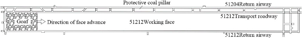
Figure 1. Layout diagram of roadway in 51,212 working face.
The coal seam mined at the 51,212 working face is the 5-1 seam, with a thickness ranging from 5.2 to 7.4 m, averaging 6.44 m. The mining height is 5.5 m, and the dip angle ranges from 0° to 1°. Borehole G23-2, located near the cut of the 51,212 working face, indicates that the overlying bedrock thickness above the working face is approximately 100 m, consisting of stable sandstone lithology. The roof comprises the following layers, from bottom to top: dark gray siltstone with a thickness ranging from 3.75 to 7.12 m, averaging 5.05 m, and grayish-white fine-grained sandstone with a thickness ranging from 24.53 to 32.76 m, averaging 27.3 m. The immediate floor consists of dark gray siltstone, with a thickness ranging from 6.75 to 11.75 m, averaging 9.52 m. A comprehensive stratigraphic column of the roof and floor of the working face is provided in Figure 2.
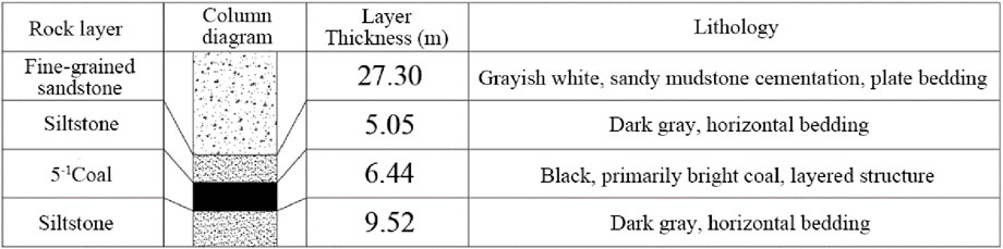
Figure 2. Columns on the top and bottom plates of the 51,212 working face.
The 51,212 working face began advancing from the cut on September 13 and had progressed 121 m by October 4. The working face has not yet experienced initial weighting, and the roof has not collapsed. However, this situation has already impacted production at the mine and may soon lead to a shutdown. Therefore, urgent roof control measures are required.
3 Rock properties and in-situ stress measurement
3.1 Rock mechanical test
The physical and mechanical properties of rock significantly influence the propagation of fractures during hydraulic fracturing. Rock mechanical parameter tests include uniaxial tensile tests, uniaxial compression tests, as well as measurements of cohesion and the internal friction angle.
3.1.1 Rock sample preparation
Fifteen groups of core samples were collected from the overlying strata of the 51,212 working face. In the laboratory, each group was processed into:
• Five cylindrical specimens with a diameter of 50 mm and a height of 100 mm for uniaxial compression tests.
• Five cylindrical specimens with a diameter of 50 mm and a height of 50 mm for shear tests.
• Five cylindrical specimens with a diameter of 50 mm and a height of 25 mm for tensile strength tests (Figure 3a).
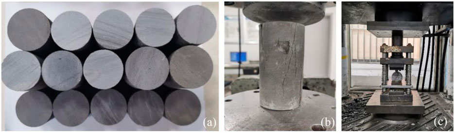
Figure 3. (a) Rock specimens. (b) Uniaxial compression experiment. (c) Brazilian splitting experiment.
3.1.2 Uniaxial compression tests
The measured compressive strength refers to the uniaxial compressive strength of the rock, which is the maximum compressive stress it can withstand before failure under uniaxial compression. In accordance with the “Methods for Determination of Physical and Mechanical Properties of Coal and Rock,” cylindrical rock samples with a diameter of 50 mm and a height of 100 mm were selected for the experiment. Figure 3b presents the uniaxial compression test diagram.
3.1.3 Uniaxial tensile tests
The tensile strength of rock is a key physical and mechanical property, typically defined as the average tensile stress on the cross-section perpendicular to the applied force when the rock specimen fails under tensile stress. However, preparing specimens and conducting uniaxial tensile loading are challenging, making direct tensile tests infrequently used. Instead, the Brazilian split test method is commonly employed for the indirect determination of rock tensile strength (Shi et al., 2023; Duan et al., 2024; Duan et al., 2025). In accordance with the “Methods for Determination of Physical and Mechanical Properties of Coal and Rock,” cylindrical rock samples with a diameter of 50 mm and a height of 25 mm are used for the Brazilian split test, as shown in Figure 3c.
3.1.4 Strength parameters
Cohesion and the internal friction angle are essential parameters for numerical simulations but are difficult to measure directly. According to the Mohr-Coulomb theory (Wu et al., 2024; Wu et al., 2025; Yan et al., 2025), the shear strength of rock is proportional to its compressive strength. Therefore, the cohesion and internal friction angle can be derived from the aforementioned tests. Table 2 presents all the parameters determined from these tests.
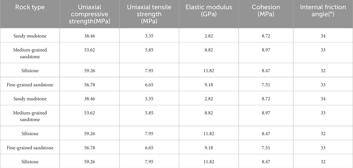
Table 2. Test results of mechanical parameters.
3.2 In-situ stress measurement
The propagation of hydraulic fractures is strongly influenced by in-situ stresses. Once a fracture extends to five times the borehole diameter, it continues to propagate in the orientation of these stresses. To better understand how hydraulic fractures propagate under field conditions and to provide a basis for subsequent numerical simulations and borehole orientation design, it is crucial to measure the in-situ stress at the working face.
To do this, a vertical measurement borehole, 10 m deep, is drilled into the roof of the working face. According to stress superposition theory, the polar coordinate expression for the stress on the borehole wall can be written as:
Where σθ represents the tangential normal stress; σH is the maximum horizontal principal stress; σh is the minimum horizontal principal stress; θ is the angle between a point on the borehole wall and σH; σr is the radial normal stress.
In the borehole, during the initial fracturing, the test hole is filled with water, creating an initial water pressure, P0. Additionally, it is necessary to overcome the tensile strength of the rock. Therefore, the water pressure at which initial fracturing occurs is denoted as Pb:
When hydraulic fractures extend beyond five times the borehole diameter, the borehole boundary no longer significantly influences their propagation, and water injection into the borehole is paused. After re-injecting water, the fracture can initiate again without needing to overcome the rock’s tensile strength. At this point, the pressure required to open the rock, known as the re-initiation pressure Pr, equals to the minimum horizontal stress σh. That is:
The vertical in-situ stress, denoted by σv, can be calculated based on the weight of the overlying strata.
Figure 4 presents a schematic diagram of in-situ stress measurement using the hydraulic fracturing method.
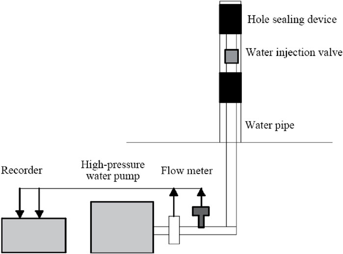
Figure 4. Schematic diagram of hydraulic fracturing method for measuring geostress.
The maximum and minimum horizontal in-situ stresses at each measurement point, based on the measurements taken at the working face, are presented in Table 3.
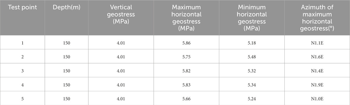
Table 3. Ground stress at each test point.
The average depth of the working face is approximately 150 m. Using the relevant formula, the vertical in-situ stress is calculated to be 3.72 MPa. Excluding the maximum and minimum values from the five in-situ stress measurement points, the average of the remaining data is σv = 4.01 MPa, σH = 5.80 MPa, and σh = 5.30 MPa. These values will be used as input for the numerical simulation in the next section.
4 Numerical simulation of hydraulic fracturing
Based on the geological overview of the working face, a comparison of common roof caving methods led to the selection of hydraulic fracturing forced roof caving to address the issue of long-distance hanging roof at the working face. The height of the forced roof caving induced by hydraulic fracturing was calculated using the mechanical parameters of the roof rock; however, the extent of the hydraulic fracturing remains unclear. This section proposes three distinct fracturing area schemes: the coal body in front of the working face, the middle of the goaf, and the entry area. It also investigates the forced roof caving zones at the working face through numerical simulation.
This research uses 3DEC discrete element software as the numerical simulation tool. As the preferred program for analyzing discontinuous rock mechanics and structural problems, 3DEC simulates discontinuous media as a collection of convex or concave polyhedra. Its natural advantage in handling discontinuous media makes it well-suited for analyzing the static and dynamic responses of discrete media under various loading conditions (Wang et al., 2006; Deng et al., 2012; Wu et al., 2018; Choi et al., 2024).
This numerical simulation primarily uses the Mohr-Coulomb yield criterion to assess rock mass failure. Displacement constraints are applied to the model: horizontal displacement is restricted at the lateral boundaries, and vertical displacement is restricted at the base.
Based on the parameters of the coal seam roof and floor rock layers, and to facilitate the modeling calculations, the thickness of each rock layer was optimized. The coal and rock mechanical parameters for modeling are presented in Table 4.
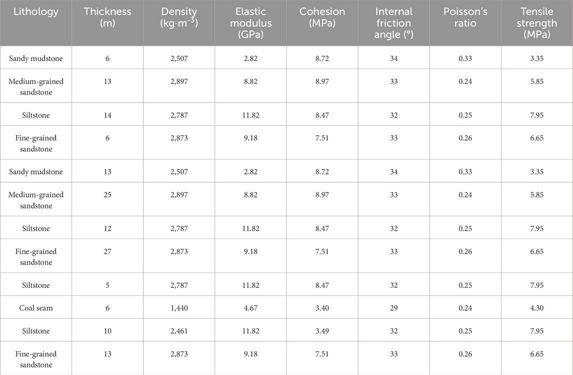
Table 4. Coal rock parameters.
The working face has an inclined length of 79 m. During the advancement of 121 m, the roof did not collapse. To better match the stress and displacement conditions of the working face, a model is established with dimensions of 250 m in length, 150 m in width, and 150 m in height, based on the thickness of the overlying strata. The numerical computation model is shown in Figure 5, where the X-axis represents the advancing direction of the working face, corresponding to its strike direction; the Y-axis represents the dip direction; and the Z-axis represents the vertical direction. In the model, in-situ stress parameters are set such that the Y-direction aligns with the maximum horizontal stress (σH = 5.80 MPa), the Z-direction aligns with the minimum stress (σv = 4.01 MPa), and the X-direction corresponds to the horizontal stress (σh = 5.30 MPa).
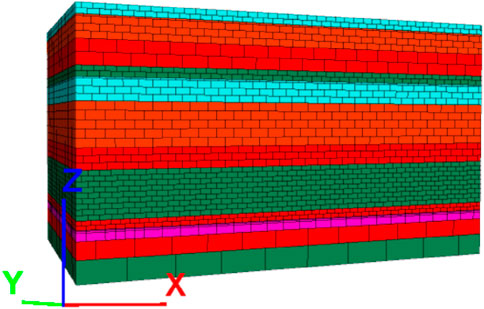
Figure 5. Numerical calculation model.
In the numerical simulation, three different schemes are established, with the fracturing areas located at the entry of the working face, the middle of the goaf, and the coal body in front of the working face, respectively. Based on the initiation and propagation patterns of hydraulic fractures, once the fractures extend beyond 3 to 5 times the borehole diameter, they begin to deflect in a direction perpendicular to the minimum principal stress. In field operations, the diameter of the fracturing boreholes typically ranges from 56 to 144 mm, and the hydraulic fractures ultimately align perpendicular to the minimum principal stress. To simplify the numerical calculations, fractures are directly incorporated into the numerical model within the fracturing area, oriented perpendicular to the minimum principal stress, with a spacing of 5 m. These fractures are modeled using fracture elements in the 3DEC software, where the tensile strength of the elements is set to zero, simulating the effect of hydraulic fractures.
Figure 6 show the stress and displacement nephograms, respectively, when the working face has been mined 120 m from the entry position and the immediate roof has not fully collapsed. As observed in the figures, the rock strata above the goaf exhibit bending deformation, with maximum subsidence occurring in the middle area of the working face, reaching approximately 2.8 m. Hydraulic fracturing is performed in different roof areas, specifically at the entry of the working face, the middle of the goaf, and the coal body in front of the working face. After pre-treating the roof, the working face advance at a rate of 2 m per step. The effectiveness of the simulation schemes is evaluated by monitoring stress changes along the monitoring lines.
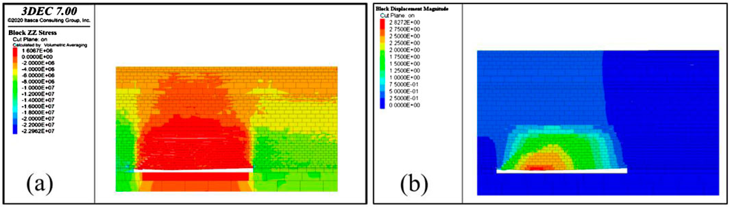
Figure 6. (a) Stress distribution and (b) displacement distribution cloud maps after gob excavation.
To investigate the initial roof weighting following hydraulic fracturing, two monitoring lines are placed in the established numerical model to record changes in vertical stress in the coal and rock mass, both in front of and behind the advancing working face. One monitoring line is positioned along the strike direction of the working face, at coordinates Y = 74.5 m and Z = 6 m in the model. The other line is arranged along the dip direction, located in the center of the working face at Z = 6 m. The arrangement of the monitoring lines is shown in Figure 7.
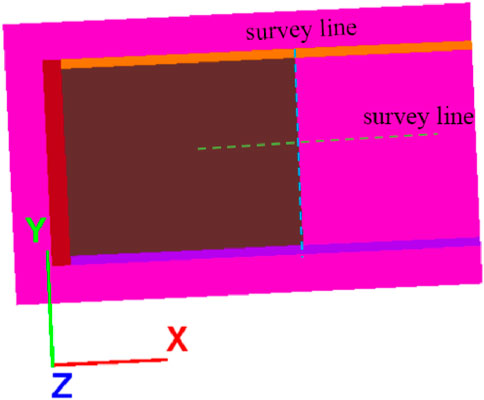
Figure 7. Layout of survey cables.
4.1 Scheme 1: The fracturing area is in the middle of the goaf (40–80 m from the entry)
The hanging roof above the goaf extends 120 m, with the greatest deformation occurring at its center. Hydraulic fracturing in the central region of the roof may lead to collapse. Therefore, this location is a potential option for the fracturing area. However, the effectiveness of roof collapse after fracturing requires further investigation through numerical simulations. In Scheme 1, the fracturing area is centered in the middle of the goaf, extending 20 m on each side. A schematic diagram of the fracturing area is shown in Figure 8a.
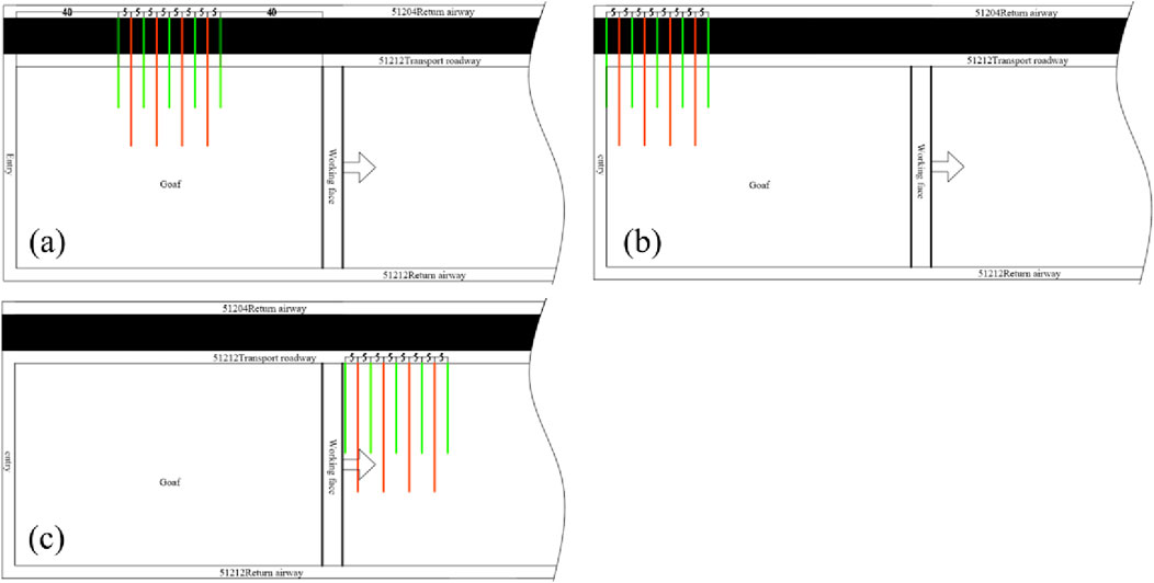
Figure 8. Fracturing areas in (a) Scheme 1, (b) Scheme 2, and (c) Scheme 3.
4.2 Scheme 2: The fracturing area is located at the entry (0–40 m from the entry)
Based on the analysis in Figures 2, 3, the reasons for the failure of the initial mining hydraulic fracturing plan are as follows: The plan has several deficiencies, including the lack of boreholes at the entry and the presence of a single fracturing horizon, which limits the ability to conduct multi-dimensional fracturing of the roof and hinders effective disruption of the roof strata’s fixed support structure. Additionally, the borehole depth is too distant from the roof’s center, reducing the effectiveness of hydraulic fracturing. Conducting deeper fracturing at the roof entry may achieve the goal of initial roof weighting, making this location a potential option for the fracturing area. The fracturing area extends 40 m along the strike of the working face, and the schematic diagram of the fracturing area for scheme 2 is shown in Figure 8b.
4.3 Scheme 3: The fracturing area is in the coal body in front of the working face (0–40 m from the working face)
The fracturing process is simpler and more convenient when performed in the coal body in front of the working face. It can be directly carried out in the return or transport airway on either side of the working face, and it is safer during on-site operations. Therefore, this area is also a viable option for hydraulic fracturing. The fracturing area in scheme 3 extends up to 40 m in front of the working face, as shown in Figure 8c.
4.4 Numerical simulation schemes: results and analysis
According to Scheme 1, hydraulic fracturing is simulated in the central area of the goaf. A series of horizontal hydraulic fractures are artificially introduced into the roof strata. The working face advances at a rate of 2 m per step. Figure 9 presents the stress and displacement nephograms of the overburden in the working face area after it has advanced 140 m from the entry.
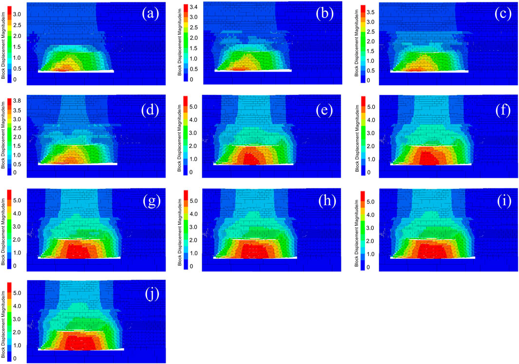
Figure 9. Displacement distribution cloud images during the advancement of the working face in Scheme 1: (a) Working face advanced to 122 m; (b) Working face advanced to 124 m; (c) Working face advanced to 126 m; (d) Working face advanced to 128 m; (e) Working face advanced to 130 m; (f) Working face advanced to 132 m; (g) Working face advanced to 134 m; (h) Working face advanced to 136 m; (i) Working face advanced to 138 m; (j) Working face advanced to 140 m.
The comparison of the numerical simulation results for three different fracturing schemes is presented in Table 5.
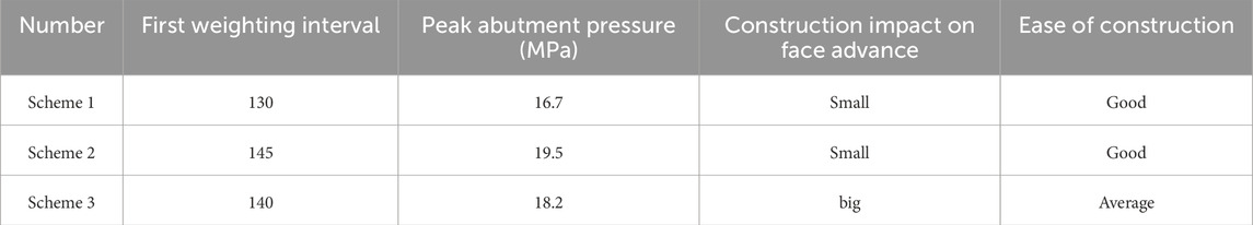
Table 5. Advantages and disadvantages of the three fracturing schemes.
Among the three schemes, Scheme 1 has the smallest initial step distance of 130 m. Specifically, when fracturing occurs in the selected area of Scheme 1 (40–80 m from the entry), the working face needs to advance only an additional 10 m for the roof to collapse. This results in a small hanging roof area, minimal weighting intensity, and a minor impact on the advancement of the working face during on-site drilling operations.
In contrast, Scheme 2 has the largest initial weighting step distance of 145 m. When fracturing occurs in the selected area of Scheme 2 (0–40 m from the entry), the working face must advance 25 more meters before the roof collapses. This leads to the largest hanging roof area and the highest weighting intensity, reaching 19.5 MPa.
Scheme 3 has an initial weighting step distance of 140 m. When fracturing is performed in the selected area of Scheme 3 (0–40 m in front of the working face), the working face must advance an additional 20 m for the roof to collapse. Although fracturing directly in front of the working face offers greater convenience, it does affect the working face’s advancement.
5 Field test
5.1 Borehole design
Based on the numerical simulation analysis in Section 4, a comparison of roof pressure conditions after hydraulic fracturing in the front section (0–40 m from the cutting eye), middle section (40–80 m from the cutting eye), and rear section (80–120 m from the cutting eye) of the goaf roof indicates that hydraulic fracturing in the middle section is the most effective. Therefore, the fracturing range is determined to be the area from 40 to 80 m from the cutting eye of the 51,212 working face. The borehole layout is shown in Figure 10, and the drilling parameters are provided in Table 6.

Figure 10. Drilling layout: (a) drillhole layout plan; (b) drillhole layout section drawing.
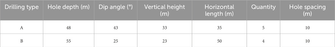
Table 6. Drilling parameters.
Due to the high fracturing height and limited fracture propagation range, using only one type of borehole makes it difficult to achieve the intended layered collapse of the roof. Therefore, two types of boreholes, A and B, are arranged for multi-level fracturing. Borehole A, the main fracturing hole, has a large inclination angle and vertical height, targeting the upper part of the roof. Borehole B, the auxiliary fracturing hole, has a smaller inclination angle and a larger horizontal length, targeting the middle part of the roof. If the boreholes were arranged in the return air roadway and transportation roadway on both sides of the 51,212 working face, the on-site construction would be highly dangerous. According to the layout of the working face roadways (Figure 1), there is a 14-m protective coal pillar between the 51,212 transportation roadway and the 51,204 return air roadway. Therefore, the boreholes are arranged in the 51,204 return air roadway, with drilling and fracturing conducted from the 51,204 return air roadway towards the goaf roof of the 51,212 working face. In summary, given the on-site construction constraints imposed by roadway space, Borehole A is designed with a depth of 48 m, an inclination angle of 43°, a vertical height of 33 m, and a horizontal length of 35 m. Borehole B has a depth of 55 m, an inclination angle of 25°, a vertical height of 23 m, and a horizontal length of 50 m.
Hydraulic fractures propagate along the direction perpendicular to the minimum principal stress, which corresponds to the direction of the maximum principal stress (Cheng et al., 2021; Gao et al., 2022b). Section 2 indicates that the azimuth of the maximum principal stress is N10.6E, which is perpendicular to the advancing direction of the working face. Therefore, the borehole orientation should be perpendicular to the advancing direction of the working face, meaning the angle between the borehole orientation and the advancing direction should be 90°.
Borehole spacing significantly influences the hydraulic fracturing effect. If the spacing is too large, hydraulic fractures will propagate over a long distance without interconnecting, leading to insufficient damage to the roof. Conversely, if the spacing is too small, the fractures will propagate only a short distance and interconnect prematurely, resulting in a limited area of roof damage. Therefore, selecting appropriate borehole spacing is crucial. The spacing primarily considers the propagation distance of the hydraulic fractures. To ensure effective fracturing, Boreholes A and B are arranged alternately with a spacing of 5 m, totaling 9 boreholes—5 of Borehole A and 4 of Borehole B.
5.2 Hydraulic fracturing equipment
Table 7 presents the basic equipment and materials required for hydraulic fracturing construction.
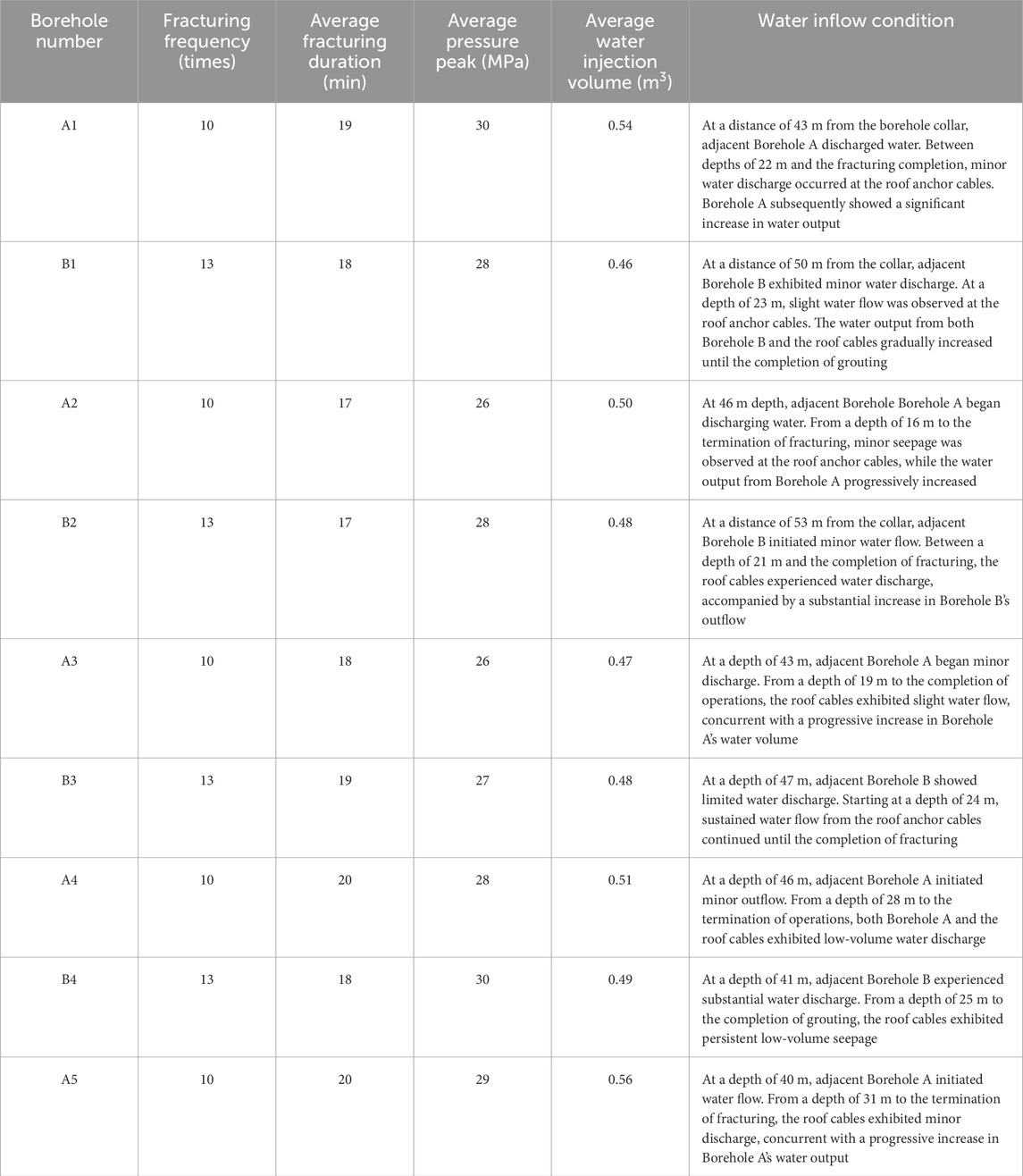
Table 7. Fracturing data of each borehole.
In addition to the equipment listed in the table above, the packer is crucial, as it determines the effectiveness of the sealing and fracturing process. Figures 11a,b presents a schematic diagram of the sealing process for the ZF-A64 packer, which features “integrated pressure-sealing” capability. This packer is reusable, suitable for both sealing and fracturing, and can be directly connected to the drill pipe. It contains two sealing capsules, with the core components being a steel ball and a limiting spring inside each capsule. Figure 11c shows the actual sealing packer used on-site.
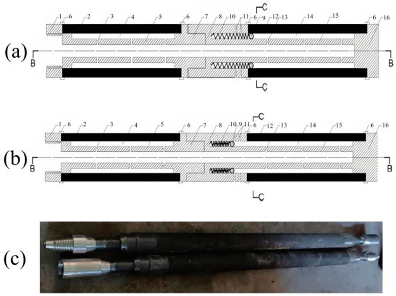
Figure 11. Schematic diagram of the “pressure-sealing integrated” hole sealer: (a) diagram of hole sealing device when not sealed, (b) diagram of hole sealing device during sealing (1-Water injection pipe coupling; 2-Rear hole sealing device capsule; 3-Rear water injection steel pipe outlet hole; 4-Rear hole sealing device capsule cavity; 5-Rear water injection steel pipe; 6-High-pressure pipe clamp; 7-Rear water injection steel pipe coupling; 8-Front water injection steel pipe coupling; 9-Steel ball; 10-Limiting spring; 11-Water outlet hole; 12-Front hole sealing device capsule; 13-Front water injection steel pipe outlet hole; 14-Front hole sealing device capsule cavity; 15-Front water injection steel pipe; 16-Steel plug structure), and (c) physical picture of a hole packer.
5.3 Hydraulic fracturing process
Hydraulic fracturing is primarily divided into two processes: drilling and fracturing. Drilling involves using a machine to create the necessary boreholes in the fracturing area in preparation for the fracturing process. Figure 12a presents a schematic diagram of the hydraulic fracturing drilling process.
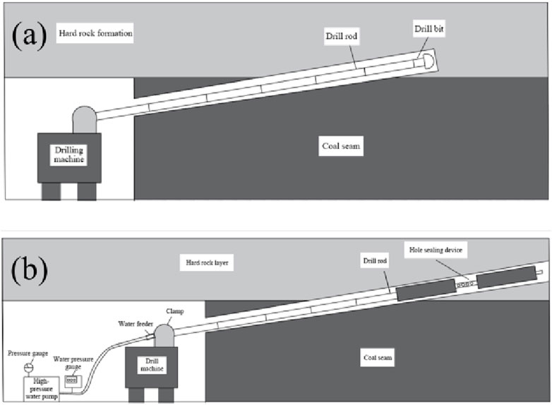
Figure 12. (a) Drilling construction diagram. (b) Roof fracturing construction diagram.
Figure 12b illustrates the fracturing construction process. Once drilling is complete, fracturing begins. First, the drill pipe is fully withdrawn from the borehole, and the drill bit is removed. Next, a packer is attached and pushed to the bottom of the hole using the drilling machine and drill pipe. Once the packer is positioned at the bottom of the borehole and the fracturing pipeline is connected, water injection fracturing begins. The high-pressure water pump is adjusted to gradually increase the pressure, while monitoring the pressure gauge until it reaches 5 MPa. After the front and rear capsules of the packer fully expand and securely adhere to the borehole wall, the water pressure is incrementally increased to initiate fracturing.
5.4 Hydraulic fracturing site fracturing effect
The effectiveness of fracturing at the hydraulic fracturing site can be assessed by analyzing various parameters and phenomena during the process. Key fracturing data, including the fracturing duration, peak pressure at each point, water injection volume at each point, and water gushing from roof anchor cables and adjacent boreholes of the same type, are recorded throughout the process.
During fracturing, varying degrees of water surging were observed from roof anchor cables and the openings of adjacent boreholes, indicating that the hydraulic fractures have extended to these areas. Figure 13 illustrates the water surging phenomena observed in the roof anchor cables and boreholes during fracturing.
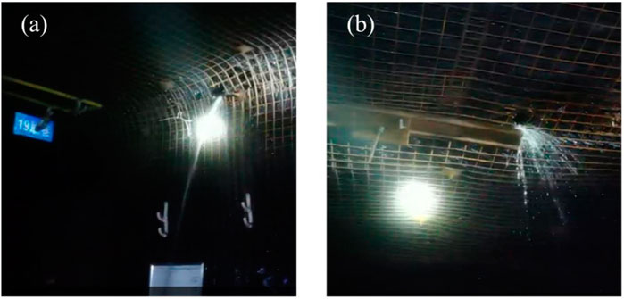
Figure 13. On site fracturing effect: (a) water outflow from drill hole; (b) water outflow from anchor cable hole.
6 On-site monitoring
6.1 Hydraulic pressure monitoring in the hydraulic shield
The 51,212 working face is equipped with 50 hydraulic shields. Monitoring data from the working resistance of the 5th, 20th, 35th, and 50th hydraulic supports were selected for analysis. A curve illustrating the variation in hydraulic support working resistance with the advancing distance of the working face was plotted, as shown in Figure 14.
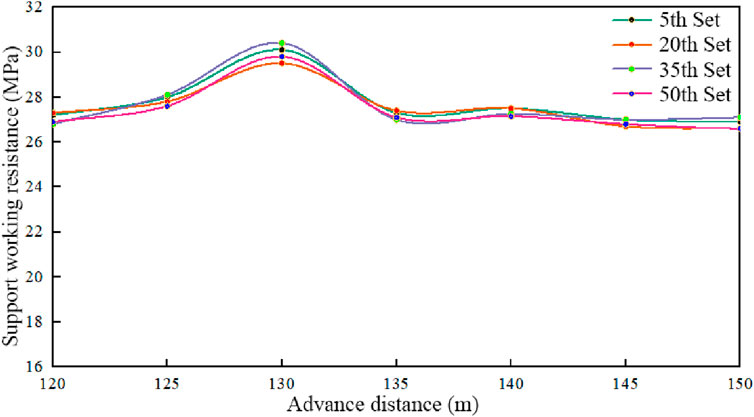
Figure 14. Working resistance of the hydraulic support.
The data shows that, regardless of the hydraulic shield, there was no significant change in the hydraulic pressure in the support shield before the working face advanced to 130 m. This was because the roof had not collapsed, and the hydraulic shield was subjected to relatively small roof pressure. However, when the working face advanced to 130 m, the hydraulic pressure increased suddenly, indicating that the roof had collapsed and the initial pressure caused the increase.
6.2 Monitoring of the axial load in the rock bolt
The ground pressure monitoring system includes anchor (cable) load cells, roof-floor dynamic alarms, and laser rangefinders. The anchor (cable) load cells measure the load on the anchor bolts and cables. Starting from the 51,212 working face cut, a set of anchor (cable) load cells was installed every 10 m along the roadway axis. The layout of the ground pressure monitoring devices is shown in Figure 15A.
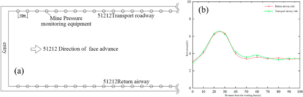
Figure 15. (a) Position of the mine pressure monitoring device. (b) Stress change of bolt.
Analyzing ground pressure within 100 m ahead of the working face provides a more accurate understanding of the roof weighting situation. Data from the anchor (cable) load cells within this 100-m range were used to plot the anchor (cable) stress variation curve, as shown in Figure 15B. As the distance from the working face increases, anchor stress on both the return air and transportation roadways initially rises, then decreases. The maximum anchor stress occurs 20–30 m ahead of the working face. Beyond 40 m, stress reaches equilibrium, and the force on the anchor bolts remains relatively small and stable, regardless of the increasing distance from the working face. Based on this analysis, it can be inferred that the initial roof pressure will occur when the working face advances another 10–20 m, specifically when it reaches the 130–140 m range.
6.3 Roadway deformation
Measurement data from roof-floor dynamic alarms and laser rangefinders within 100 m ahead of the working face were analyzed, and variation curves of roof-floor and side convergence were plotted, as shown in Figure 16.
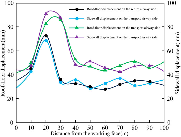
Figure 16. Tunnel deformation.
Figure 17 illustrates that the variation curves of roof-floor convergence, with respect to the distance from the working face, are nearly identical on both the return air roadway side and the transportation roadway side. As the distance from the working face increases, roof-floor convergence on both sides initially increases and then decreases, with the maximum convergence occurring approximately 20 m ahead of the working face. Near the working face, roof-floor convergence remains small due to the influence of advanced hydraulic supports. At greater distances, the area enters a stress equilibrium zone, where roof-floor convergence remains minimal and does not change with increasing distance from the working face. This analysis indicates that initial roof weighting occurs when the working face has advanced approximately 10 m, reaching a distance of around 130 m.
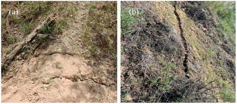
Figure 17. Surface fractures: (a) surface fracture 1; (b) surface fracture 2.
6.4 The surface subsidence
The hydraulic fracturing operation was completed on October 13, and the working face continued to advance. Following the roof collapse, personnel were assigned to inspect the surface subsidence above the working face daily. The inspection results show that, except for three new fractures on October 17, no additional fractures appeared on October 18, 19, or 20. On October 21, five new fractures emerged, but no new fractures were observed on October 22. On October 23, five more fractures appeared on the surface. Surface rock movement observations indicated that, apart from a maximum surface subsidence of 0.64 m on October 17, no subsidence was recorded on October 18, 19, or 20. On October 21, the maximum subsidence was 0.53 m, followed by 0.128 m on October 22 and 0.185 m on October 23.
On October 23, the first new fracture was discovered approximately 238.29 m from the cutting edge of the 51,212 working face. This fracture measured 15 m in length and 0.3 m in width. The second fracture, located about 196.78 m from the cut, was 37.41 m long and had a maximum width of 0.35 m. The third fracture, about 208.53 m from the cut, was 17.95 m long and 0.2 m wide. The fourth fracture appeared approximately 203.55 m from the cut, with a length of 18.33 m and a maximum width of 0.3 m. The fifth fracture, located around 213.49 m from the cut, measured 14.18 m in length and 0.3 m in width. These five fractures had an average surface elevation of approximately 1,094.78 m, while the roof elevation of the working face was about 980.56 m, with an overlying bedrock thickness of 103.24 m.
The appearance of fractures and surface subsidence (Figure 17) indicates that the collapse has extended to the surface, confirming that the hydraulic fracturing-induced caving has successfully achieved the goal of controlling the hard roof.
7 Conclusion
This paper presents the 51,212 working face at Guojiawan Coal Mine as an engineering case study, where a massive 121-m-long roof was suspended behind the longwall face. A comprehensive framework for the hydraulic fracturing technique has been developed through this research. A series of rock mechanics tests were conducted to assess the geotechnical and geological conditions at the mine. A robust 3DEC numerical simulation was also performed to optimize the hydraulic fracturing design for on-site application. Finally, a detailed field application of the hydraulic fracturing technique was implemented, followed by extensive site monitoring.
The simulation results indicate that hydraulic fracturing in the central part of the goaf reduces the initial pressure step distance, accelerates roof collapse, and does not interfere with production at the working face. The initial caving step distance was approximately 130 m.
In the field. Fracturing was carried out 40–80 m from the cut, with the following drilling parameters: five A-type boreholes, each 48 m deep with a 43° inclination angle, and four B-type boreholes, each 55 m deep with a 25° inclination angle. The drilling direction was perpendicular to the advancing direction of the working face, with a hole spacing of 5 m.
After fracturing, hydraulic pressure monitoring data from the hydraulic shield showed a sudden increase when the working face advanced to approximately 130 m, indicating roof collapse and the onset of initial pressure. This observation was consistent with the monitoring data on roadway deformation and the axial load in the rock bolts. Surface fractures and subsidence in the goaf area further confirmed the effectiveness of the hydraulic fracturing-based forced roof caving plan.
Data availability statement
The original contributions presented in the study are included in the article/supplementary material, further inquiries can be directed to the corresponding authors.
Author contributions
XW: Software, Conceptualization, Investigation, Writing – original draft, Formal Analysis, Methodology. WG: Validation, Conceptualization, Writing – original draft, Data curation, Visualization, Formal Analysis. QH: Writing – review and editing, Supervision, Resources, Conceptualization, Funding acquisition, Project administration, Methodology. XG: Investigation, Writing – review and editing, Formal Analysis, Software, Visualization. BL: Writing – review and editing, Validation, Formal Analysis, Data curation, Conceptualization, Visualization, Investigation. QL: Resources, Validation, Software, Investigation, Writing – review and editing. YY: Resources, Writing – review and editing, Investigation, Data curation, Validation. YG: Writing – review and editing, Investigation, Methodology, Visualization, Formal Analysis.
Funding
The author(s) declare that financial support was received for the research and/or publication of this article. The work is financially supported by the National Key R&D Program of China (2022YFC2905600), the National Natural Science Foundation of China (U23B2091, 52404157), the Postdoctoral Fellowship Program of China Postdoctoral Science Foundation (GZB20240825), and the Jiangsu Funding Program for Excellent Postdoctoral Talent (2024ZB700).
Conflict of interest
Authors XW and WG were employed by China Coal Energy Research Institute Co., Ltd. Authors YY and YG were employed by Shijiazhuang Coal Mining Machinery Co., Ltd.
The remaining authors declare that the research was conducted in the absence of any commercial or financial relationships that could be construed as a potential conflict of interest.
Generative AI statement
The author(s) declare that no Generative AI was used in the creation of this manuscript.
Publisher’s note
All claims expressed in this article are solely those of the authors and do not necessarily represent those of their affiliated organizations, or those of the publisher, the editors and the reviewers. Any product that may be evaluated in this article, or claim that may be made by its manufacturer, is not guaranteed or endorsed by the publisher.
Abbreviations
σH, the maximum horizontal principal stress, Pa; σh, the minimum horizontal principal stress, Pa; σv, the vertical stress, Pa; σ3, the minimum principal stress, Pa; σθ, the tangential normal stress, Pa; θ, the angle between a point on the borehole wall and σH, °; σr, the radial normal stress, Pa; P0, the initial water pressure, Pa; Pb, the water pressure at which the initial cracking occurs, Pa; Pr, the re-initiation pressure, Pa.
References
Chen, D., Sun, C., and Wang, L. (2021). Collapse behavior and control of hard roofs in steeply inclined coal seams. B. Eng. Geol. Environ. 80 (2), 1489–1505. doi:10.1007/s10064-020-02014-3
Cheng, Y., Zhang, Y., Yu, Z., and Hu, Z. (2021). Investigation on reservoir stimulation characteristics in hot dry rock geothermal formations of China during hydraulic fracturing. Rock Mech. Rock. Eng. 54 (8), 3817–3845. doi:10.1007/s00603-021-02506-y
Choi, B., Oh, S., and Kim, H. (2024). 3DEC simulation for single hole blasting in rock plates. Sci. Technol. Energ. Ma. 85 (5), 35–45.
Deng, J. Q., Lin, C., Yang, Q., Liu, Y. R., Tao, Z. F., and Duan, H. F. (2016). Investigation of directional hydraulic fracturing based on true tri-axial experiment and finite element modeling. Comput. Geotech. 75, 28–47. doi:10.1016/j.compgeo.2016.01.018
Deng, X., Zhu, J., Chen, S., and Zhao, J. (2012). Some fundamental issues and verification of 3DEC in modeling wave propagation in jointed rock masses. Rock Mech. Rock. Eng. 45 (5), 943–951. doi:10.1007/s00603-012-0287-1
Duan, H., Ma, D., Kong, S., Ma, Z., and Zou, L. (2025). Hydraulic erosion-heat transfer coupling model for coal and geothermal energy co-exploitation. Renew. Energ. 248, 123109. doi:10.1016/j.renene.2025.123109
Duan, H., Ma, D., Zou, L., Xie, S., and Liu, Y. (2024). Co-exploitation of coal and geothermal energy through water-conducting structures: improving extraction efficiency of geothermal well. Renew. Energ. 228, 120666. doi:10.1016/j.renene.2024.120666
Gao, X., Zhang, Y., Cheng, Y., Yu, Z., Hu, Z., and Huang, Y. (2023). Heat extraction performance of fractured geothermal reservoirs considering aperture variability. Energy 269, 126806. doi:10.1016/j.energy.2023.126806
Gao, X., Zhang, Y., Cheng, Y., Yu, Z., and Huang, Y. (2022a). Impact of fractures with multi-scale aperture variability on production observations of geothermal reservoir units. J. Hydrol. 615, 128693. doi:10.1016/j.jhydrol.2022.128693
Gao, X., Zhang, Y., Hu, J., Huang, Y., Liu, Q., and Zhou, J. (2022b). Site-scale bedrock fracture modeling of a spent fuel reprocessing site based on borehole group in Northwest, China. Eng. Geol. 304, 106682. doi:10.1016/j.enggeo.2022.106682
Ham, S.-M., and Kwon, T.-H. (2020). Photoelastic observation of toughness-dominant hydraulic fracture propagation across an orthogonal discontinuity in soft, viscoelastic layered formations. Int. J. Rock Mech. Min. 134, 104438. doi:10.1016/j.ijrmms.2020.104438
He, Z., Lu, C., Zhang, X., Guo, Y., Meng, Z., and Xia, L. (2022). Numerical and field investigations of rockburst mechanisms triggered by thick-hard roof fracturing. Rock Mech. Rock. Eng. 55 (11), 6863–6886. doi:10.1007/s00603-022-03002-7
Hou, Z., Cheng, H., Sun, S., Chen, J., Qi, D., and Liu, Z. (2019). Crack propagation and hydraulic fracturing in different lithologies. Appl. Geophys. 16 (2), 243–251. doi:10.1007/s11770-019-0764-3
Hu, J., Lei, T., Zhou, K., Luo, X., and Yang, N. (2011). Mechanical response of roof rock mass unloading during continuous mining process in underground mine. T. nonferr. Metal. Soc. 21 (12), 2727–2733. doi:10.1016/S1003-6326(11)61116-3
Ismail, A., and Azadbakht, S. (2024). A comprehensive review of numerical simulation methods for hydraulic fracturing. Int. J. Numer. Anal. Met. 48 (5), 1433–1459. doi:10.1002/nag.3689
Jiang, L., Jiao, H., Wang, Y., and Wang, G. (2021). Comprehensive safety factor of roof in goaf underdeep high stress. J. Cent. South Univ. 28 (2), 595–603. doi:10.1007/s11771-021-4624-y
Lai, C., Zheng, Z., Dressaire, E., Wexler, J. S., and Stone, H. A. (2015). Experimental study on penny-shaped fluid-driven cracks in an elastic matrix. P. Roy. Soc. A-Math. Phy. 471 (2182), 20150255. doi:10.1098/rspa.2015.0255
Lekontsev, Y. M., and Sazhin, P. V. (2014). Directional hydraulic fracturing in difficult caving roof control and coal degassing. J. Min. Sci. 50 (5), 914–917. doi:10.1134/S106273911405010X
Li, K., He, Z., Zhang, Z., Zou, Y., Wang, X., and Xie, F. (2023). A new template matching based acoustic emission detection procedure and its application in laboratory hydraulic fracturing experiment. Chin. J. Geophys-Ch. 66 (10), 4386–4401. doi:10.6038/cjg2022Q0566
Li, Z., Zhang, Y., Gao, X., Ma, D., Fan, L., Li, G., et al. (2025). Characterizing the deformation, failure, and water-conducting fractures evolution of shallow weakly cemented overburden under coal mining. Front. Earth Sci. 13. doi:10.3389/feart.2025.1538324
Lin, H., Deng, J., Liu, W., Xie, T., Xu, J., and Liu, H. (2018). Numerical simulation of hydraulic fracture propagation in weakly consolidated sandstone reservoirs. J. Cent. South Univ. 25 (12), 2944–2952. doi:10.1007/s11771-018-3964-8
Liu, H., Hao, C., Han, Z., Liu, Q., Wang, H., Liang, J., et al. (2023). Study on the mechanism of a hanging roof at a difficult caving end in a fully-mechanized top coal caving face. Sustainability 15 (1), 812. doi:10.3390/su15010812
Ma, J., L, H., Guo, X., Tian, F., and Guo, H. (2022). A control method for hydraulic fracturing of the hard roof with long and short boreholes. Front. Mater. 9, 1035815. doi:10.3389/fmats.2022.1035815
Shao, L., Huang, B., Zhao, X., Li, H., and Chen, S. (2024). Top coal weakening by pulse hydraulic fracturing and roof cutting by directional hydraulic fracturing for control of hanging roof in the face end of fully mechanized top coal caving. Lithosphere 2024 (4), 1–19. doi:10.2113/2024/lithosphere_2024_150
Shi, X., Feng, G., Bai, J., Zhu, C., Wang, S., Wang, K., et al. (2023). Brazil splitting characteristics of coal-backfilling composite structure with different interface angles: insights from laboratory experiment and numerical simulation. J. Cent. South Univ. 30 (1), 189–201. doi:10.1007/s11771-023-5231-x
Sun, R., Zhao, Z., Yang, W., and Li, H. (2024). Research and application of hydraulic fracturing axial roof cutting technology for gently inclined hard roof based on abrasive jet. Front. Earth Sci. 12. doi:10.3389/feart.2024.1485210
Tang, S., Dong, Z., Wang, J., and Mahmood, A. (2020). A numerical study of fracture initiation under different loads during hydraulic fracturing. J. Cent. South Univ. 27 (12), 3875–3887. doi:10.1007/s11771-020-4470-3
Tao, M., Zhao, Y., and Guo, J. (2023). Arch model of roof and optimization of roof-contacted filling rate in two-step mining. T. Nonferr. Metal. Soc. 33 (6), 1893–1905. doi:10.1016/S1003-6326(23)66230-2
Wang, W., Li, X., Zuo, Y., Zhou, Z., and Zhang, Y. (2006). 3DEC modeling on effect of joints and interlayer on wave propagation. T. Nonferr. Metal. Soc. 16 (3), 728–734. doi:10.1016/S1003-6326(06)60129-5
Wu, J., Lin, W., and Hu, H. (2018). Post-failure simulations of A large slope failure using 3DEC: the hsien-du-Shan slope. Eng. Geol. 242, 92–107. doi:10.1016/j.enggeo.2018.05.018
Wu, J., Wong, H. S., Zhang, H., Yin, Q., Jing, H., and Ma, D. (2024). Improvement of cemented rockfill by premixing low-alkalinity activator and fly ash for recycling gangue and partially replacing cement. Cem. Concr. Comp. 145 (0), 105345. doi:10.1016/j.cemconcomp.2023.105345
Wu, J., Yang, S., Williamson, M., Wong, H. S., Bhudia, T., Pu, H., et al. (2025). Microscopic mechanism of cellulose nanofibers modified cemented gangue backfill materials. Adv. Compos. Hybrid. Ma 8 (2), 177. doi:10.1007/s42114-025-01270-9
Wu, W., Feng, G., Yu, X., Bai, J., Wang, X., and Zhao, X. (2023). Investigation into pressure appearances and hydraulic fracturing roof-cutting technology in mining working face under residual pillars: a case study. Energies 16 (9), 3914–3917. doi:10.3390/en16093914
Yan, J., Ma, D., Gao, X., Li, Q., and Hou, W. (2025). Fault zone mechanical response under co-exploitation of mine and geothermal energy: the combined effect of pore pressure and mining-induced stress. Int. J. Coal Sci. Techn. 12 (33), 33. doi:10.1007/s40789-025-00786-1
Yang, W., Geng, Y., Zhou, Z., Li, L., Ding, R., Wu, Z., et al. (2020). True triaxial hydraulic fracturing test and numerical simulation of limestone. J. Cent. South Univ. 27 (10), 3025–3039. doi:10.1007/s11771-020-4526-4
Zhang, F., Wang, X., Bai, J., Wu, B., Wang, G., Li, J., et al. (2022). Study on hydraulic fracture propagation in hard roof under abutment pressure. Rock Mech. Rock Eng. 55 (10), 6321–6338. doi:10.1007/s00603-022-02989-3
Zhou, F., Su, H., Liang, X., Meng, L., Yuan, L., Li, X., et al. (2019). Integrated hydraulic fracturing techniques to enhance oil recovery from tight rocks. Petrol. explor. Dev. 46 (5), 1065–1072. doi:10.1016/S1876-3804(19)60263-6
Zhuang, J., Mu, Z., Cai, W., He, H., Lee, J. H., Xi, G., et al. (2024). Multistage hydraulic fracturing of a horizontal well for hard roof related coal burst control:Insights from numerical modelling to field application. Int. J. Min. Sci. Techno. 34 (8), 1095–1114. doi:10.1016/j.ijmst.2024.08.008
Keywords: hydraulic fracturing, hanging roof, longwall face, coal mine, field test
Citation: Wu X, Gu W, He Q, Gao X, Liu B, Li Q, Yang Y and Gong Y (2025) A robust framework of hydraulic fracturing applications for competent roof caving in underground longwall operations. Front. Earth Sci. 13:1594895. doi: 10.3389/feart.2025.1594895
Received: 17 March 2025; Accepted: 05 May 2025;
Published: 29 May 2025.
Edited by:
Hao Shi, Anhui University of Science and Technology, ChinaReviewed by:
Liangliang Guo, Taiyuan University of Technology, ChinaZhihong Lei, Southwest Jiaotong University, China
Copyright © 2025 Wu, Gu, He, Gao, Liu, Li, Yang and Gong. This is an open-access article distributed under the terms of the Creative Commons Attribution License (CC BY). The use, distribution or reproduction in other forums is permitted, provided the original author(s) and the copyright owner(s) are credited and that the original publication in this journal is cited, in accordance with accepted academic practice. No use, distribution or reproduction is permitted which does not comply with these terms.
*Correspondence: Qingyuan He, NTc4M0BjdW10LmVkdS5jbg==; Xuefeng Gao, dGJoMzk4QGN1bXQuZWR1LmNu