 Peng Xu1
 Xiangshuai Song
- 1CCCC South China Construction and Development Co., Ltd., Shenzhen, China
- 2CCCC Second Harbor Engineering Company Ltd., Wuhan, China
- 3School of Water Resources and Hydropower, Hunan Polytechnic of Water Resources and Electric Power, Changsha, China
In urban regions with karst developments, grouting is commonly utilized to fill cavities. However, the extent and control standards of grouting reinforcement are primarily determined through experience and field testing, which poses challenges in ensuring its effectiveness. Based on the instability mechanism of surrounding rocks in underwater karst shield tunnels, this study develops a mechanical model for analyzing the grouting reinforcement extent of such tunnels using strength theory. The reinforcement range for karst formations at various tunnel locations is clarified, and corresponding grouting reinforcement control standards are proposed based on cusp catastrophe theory. The findings indicate the following: the primary cause of surrounding rock instability in underwater karst shield tunnels is that the reduction in surrounding rock thickness during shield tunneling modifies the original constraints and boundary conditions and disrupts the initial equilibrium state. These changes influence the water content of the surrounding rocks and disturb the surrounding rock and soil mass, leading to surrounding rock instability. When grouting causes damage to the surrounding rocks between the karst and tunnel, the system is simplified into cantilever beam and plate models for analysis. It is determined that the grouting reinforcement extent is primarily influenced by factors such as karst size, properties of the karst filling material, and tunnel span. The total potential energy of the rock mass between the karst and tunnel is calculated, leading to the development of an instability and catastrophe model for the surrounding rocks. The proposed grouting reinforcement control standards are mainly dependent on factors such as the distance of the karst, characteristics of the reinforced surrounding rocks, shield machine support force, material properties post-reinforcement, and karst size.
1 Introduction
Karst presents a significant challenge in tunnel construction, posing substantial risks and leading to serious consequences. During excavation, the exposure of previously undetected karst formations can result in mud and water inrush accidents, leading to casualties, damage to construction equipment, and severe disruptions to the project schedule (Su et al., 2025; Chen et al., 2024). In urban settings, karst tunnel construction may induce deformation in the overlying strata, potentially causing settlement, cracking, or, in severe cases, collapse of surface structures. Furthermore, the loss of large volumes of karst filling material and the subsequent destabilization of the strata can contribute to surface collapse and roof caving (Alija et al., 2013; Huang et al., 2017; Zhao et al., 2024). Additionally, operational disruptions, including vehicle interruptions caused by karst-related issues, have been frequently reported.
For the construction of subway tunnels in urban karst areas, existing research primarily addresses the development patterns and characteristics of karst formations, the response of surface environments to disturbances caused by subway tunnel construction, the mechanisms of disturbance and instability in karst strata, and the engineering techniques for managing tunnels crossing karst regions (Liu et al., 2024; Wei et al., 2020; Su et al., 2021; Fu et al., 2020; Lan et al., 2021; Li et al., 2016). Karst grouting treatment is a widely employed engineering method that involves injecting specialized slurry into cavities to fill voids and reinforce the surrounding rock mass, thereby enhancing geological stability and load-bearing capacity. This technique relies on the fluidity and cohesiveness of the slurry to bond loose rock particles, creating an integrated structure and improving the strength of the rock mass. Current grouting applications for underwater karst shield tunnels are predominantly based on analyses of engineering case studies. For example, based on the engineering background of Guangzhou Metro shield tunneling through karst areas, Zhang et al. (2018) proposed a new controllable grouting method and two corresponding grouting materials to pre reinforce the underwater karst area before the shield tunnel passes through (Yang et al., 2020). In the Guangzhou Metro Line five karst shield tunneling project, Cui and Wang, (2008) compared the effectiveness of sleeve valve pipe grouting, perforated pipe grouting, and steel jacket grouting in typical karst regions. Ou et al. (2024) drew on the engineering experience of multiple large-scale water inrush disasters in the Dejiang Tunnel to qualitatively and quantitatively analyze the water inrush mechanism. The principle of “combining drainage and blockage” was adopted to solve the water inrush problem, and the innovative application of high-pressure grouting with membrane bags effectively solved the series connected karst pipeline. In a practical shield tunneling project through karst formations, Ma, (2018) proposed a grouting treatment method incorporating paste slurry and a combination of low-pressure pulse sealing with high-pressure pulse squeezed grouting for single karst formations, while for bead-shaped karst, a technique involving gradually segmented grouting from top to bottom with a multi-layer casing was introduced. A review of the literature indicates that control standards for grouting in underwater karst shield tunnels remain unexplored. For such grouting projects, defining reasonable reinforcement ranges is crucial to ensuring smooth construction progress and the safe operation of shield tunnels. Establishing appropriate grouting reinforcement parameters can also help optimize project costs and reduce construction timelines. However, most existing grouting projects rely on empirical methods and on-site testing to determine reinforcement ranges and requirements, which compromises engineering safety and leads to excessive consumption of manpower and financial resources.
Given these considerations, this study first examines the instability mechanism of surrounding rocks in underwater karst shield tunnels and subsequently develops a cantilever beam mechanics model. Utilizing strength theory, the grouting reinforcement range is determined for various positions of underwater karst relative to the shield tunnel. Additionally, the corresponding grouting reinforcement requirements are calculated using a fixed support plate mechanics model. The findings of this research offer a reliable approach for analyzing and establishing grouting control standards for underwater karst shield tunnels.
2 Instability mechanism of surrounding rocks in underwater karst shield tunnels
The formation process of underwater karst indicates that karst formations are typically in a highly stable state (Zou et al., 2025) However, when a shield tunnel passes through a karst region, the tunneling process induces stress redistribution, residual stress release, and variations in pore water pressure within a specific range around the tunnel. These changes result in deformation, displacement, and alterations in the physical and mechanical properties of the surrounding rocks, potentially leading to engineering failures such as tunnel face instabilities and water and mud inrush incidents within the tunnel (Yang et al., 2017).
Considering the alterations in the stress state of the surrounding rocks induced by shield tunneling, the primary factors contributing to the instability of surrounding rocks in underwater karst shield tunnels can be summarized as follows:
(1) During shield tunneling, a sudden reduction in the thickness of the surrounding rocks leads to substantial alterations in their initial constraints and boundary conditions, disrupting the original stress equilibrium state. This results in stress redistribution and a decrease in the strength and stiffness of the surrounding rocks. The gravitational influence of construction equipment, such as the shield tunneling machine, also affects the surrounding rock mass. When the karst is positioned above the tunnel, tensile stress acts on the surrounding rocks on the tunnel side, while compressive stress is exerted on the rocks adjacent to the karst. Conversely, when the karst is beneath the tunnel, the stress distribution is reversed. If the karst is located on the tunnel’s side, significant stress concentration occurs in the surrounding rocks. Ultimately, instability failure takes place when the tensile stress generated in the surrounding rocks exceeds their tensile strength.
(2) Shield tunneling significantly influences the water content of the surrounding rocks. Tunnel excavation causes the accumulation of groundwater around the tunnel, leading to variations in pore water pressure and seepage pressure, which can compromise the structural integrity of the surrounding rocks. Additionally, the excavation process and the weight of the shield machine induce stress variations in the surrounding rocks, further altering water pressure and other influencing factors within the rock mass. Under the combined effects of fluid-solid coupling between the surrounding rocks and groundwater, the stability of the surrounding rocks near the tunnel is highly susceptible to failure.
(3) Shield tunneling induces substantial construction disturbances in the surrounding rock and soil mass. This is primarily reflected in the impact of structures such as the shield cutterhead and shield shell, which cause significant perturbations and loosening of the surrounding rock and soil mass. Additionally, modifications in crack channels within the surrounding rocks occur, intensifying the damage caused by crack water and penetrating water. Furthermore, as the surrounding rocks loosen, previously enclosed high-pressure water and gas are partially released, further exacerbating the loosening of the rock and soil mass and, in some cases, directly leading to structural failure.
3 Extent of grouting reinforcement for underwater karst shield tunnels
3.1 Basic assumptions
The stress state of underwater karst formations positioned at various locations relative to the shield tunnel is analyzed, and the grouting reinforcement extent for these underwater karst shield tunnels is determined by assessing the safe distance between the tunnel and the karst. Based on the requirements of the analysis, the following assumptions are proposed:
(1) The surrounding rocks between the underwater karst and the shield tunnel are considered a homogeneous body, and the karst remains unchanged throughout the shield tunneling process.
(2) The arching effect of the surrounding rocks between the underwater karst and the shield tunnel is disregarded, and the surrounding rocks are simplified into beam and plate structures for elastic calculations.
(3) Before shield tunneling, the karst is assumed to be in a stable state, and the loads acting on the surrounding rocks between the underwater karst and the shield tunnel are simplified as either concentrated or uniformly distributed loads.
3.2 Establishment of cantilever beam and plate mechanics models
Due to the influence of drilling and grouting pressure during the grouting process in underwater karst shield tunnels, the surrounding rocks between the underwater karst and the shield tunnel experience a certain degree of damage, leading to the formation of numerous cracks and gaps. Therefore, these surrounding rocks are simplified into cantilever beam and plate models for stress analysis. In this model, let S represent the length of the cantilever and B denote the crack cutting width. Based on elastic theory, the model behaves as a cantilever beam when S > 5B and transitions into a cantilever plate model when S ≤ 5B (Shunying et al., 2024; Rees, 2018; Carpinteri A., 2017). The mechanical model of the cantilever beam is illustrated in Figure 1a, while the cantilever plate mechanics model is depicted in Figure 1b.
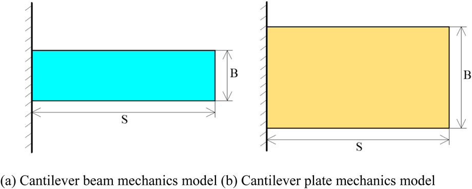
Figure 1. Cantilever beam and cantilever plate mechanics models. (a) Cantilever beam mechanics model (b) Cantilever plate mechanics model.
3.3 Karst above the tunnel
When the underwater karst is positioned above the shield tunnel, the rock and soil mass between the karst and the tunnel are influenced by the surrounding rock weight, karst-filling material, and groundwater. The stress condition of the surrounding rocks in this scenario can be simplified into a cantilever beam model. Let the karst water pressure be Pw, the pressure exerted by the karst filling material be Pa, and the weight of the surrounding rocks be Pr. Under these conditions, the cantilever beam stress model is represented schematically in Figure 2.
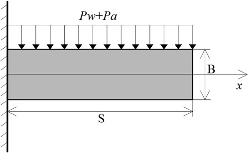
Figure 2. Cantilever beam stress model when the karst is above the tunnel.
According to Figure 2, the maximum shear stress
Where S represents the span of the surrounding rocks, and Pmax denotes the maximum shear force of the cantilever beam.
When the shield tunneling machine remains in a stable state during excavation, the maximum shear stress should not exceed the shear strength of the surrounding rock (
By combining Equation 1, it is evident that a minimum reinforcement range exists to maintain the stability of the surrounding rocks. Thus,
According to Figure 2, the maximum shear force Pmax satisfies
Therefore, by combining Equations 2, 3, when the underwater karst is positioned above the tunnel, the grouting reinforcement range h1 is
According to Equation 4, it is important to note that, since the surrounding rocks beneath the karst are in a fully saturated state, this factor must be considered when calculating the weight of the surrounding rocks.
3.4 Karst below the tunnel
When the underwater karst is positioned below the shield tunnel, the rock and soil mass between the karst and the tunnel are influenced by the weights of the saturated surrounding rocks and the shield machine. The stress condition of the surrounding rocks in this scenario is simplified into a cantilever beam model. Let P1 represent the load of the shield tunneling machine,
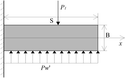
Figure 3. Cantilever beam stress model when the karst is under the tunnel.
As shown in Figure 3, similarly, by referring to Equations 1, 2, during shield excavation, a minimum reinforcement range is required to maintain the stability of the surrounding rocks.
According to Figure 3, the maximum shear force
Therefore, based on Equation 5, when the underwater karst is located below the tunnel, the grouting reinforcement range h2 is Equation 6
3.5 Karst on the tunnel side
When the underwater karst is positioned on the side of the shield tunnel, the stress condition of the surrounding rocks between the underwater karst and the shield tunnel can be simplified as an elastic plate model. Let Pw denote the uniformly distributed load of karst water pressure on the surrounding rock wall, and Pa represent the uniformly distributed load of the karst filling material on the surrounding rock wall. Under these conditions, the elastic plate stress model shown in Figure 4 is satisfied.
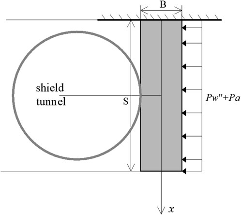
Figure 4. Elastic plate stress model when the karst is located on the side of the tunnel.
According to Figure 4, similarly, by referring to Equations 1, 2, during shield excavation, a minimum reinforcement range is required to maintain the stability of the surrounding rocks.
According to Figure 4, the maximum shear force
Therefore, based on Equation 7, when the underwater karst is located on the side of the tunnel, the grouting reinforcement range h3 is Equation 8
4 Control standards for grouting reinforcement of underwater karst shield tunnels
4.1 Grouting reinforcement model based on the cusp catastrophe theory
The cusp catastrophe theory is widely applied to analyze instability problems induced by tunnel excavation, providing both the necessary and sufficient conditions for the instability of surrounding rocks during excavation (Liao et al., 2022; Liu et al., 2024). Therefore, in the context of underwater karst shield tunnels, the instability condition of the surrounding rocks without grouting reinforcement is first determined using the cusp catastrophe theory. To ensure stability after grouting, it is essential to enhance the surrounding rock parameters to prevent an unstable state. Consequently, the improved geological condition is established as the standard for grouting reinforcement in underwater karst shield tunnels.
After grouting reinforcement, shield tunneling is carried out. For each shield tunneling cycle step, the state variable En of each surrounding rock unit is:
where n represents the unit number of the model, m denotes the cycle step of shield tunneling, and E = f(t) expresses the variation in En for each excavation. Expanding Equation 9 using the Taylor series gives, considering that the expansion of the project is mainly influenced by the first five items, while subsequent terms have negligible effects, it can be approximated as:
where
Letting Δ be the control parameter, Equation 10 can be rewritten in the standard form of the cusp catastrophe theory:
where
Taking the derivative of Equation 11 leads to the bifurcation set equation:
According to the cusp catastrophe theory, when Δ > 0, the surrounding rocks after grouting reinforcement remain in a stable state during shield tunneling. Therefore, the condition for satisfying the grouting reinforcement standard is Δ > 0.
4.2 Karst above the tunnel
When the underwater karst is positioned above the shield tunnel, the grouting-reinforced structure between the karst and the tunnel is influenced by the weight of the surrounding rocks and groundwater. Under these loads, the surrounding rocks experience vertical displacement during shield tunneling. If this vertical displacement exceeds a critical threshold, instability occurs. Therefore, the grouting reinforcement standard is defined to ensure that the vertical displacement of the surrounding rocks remains below the critical value during shield tunneling.
4.2.1 Basic assumptions and model establishment
According to actual site conditions, if L represents the span between the karst and the tunnel, d denotes the distance between them, E is the elastic modulus of the formation after grouting reinforcement, Pa is the weight of the reinforced structure following cave treatment, Pw indicates the water pressure exerted by groundwater, P be the weight of the surrounding rocks, and q represents the support force provided by the shield tunnel segments. The following assumptions are made:
The formation is considered intact after grouting reinforcement, and the surrounding rocks above the shield tunnel are simplified as a beam structure for stress analysis. 2) The above loads act on the shield tunnel in the form of uniformly distributed loads. 3) The stress at both ends of the tunnel is simplified as a horizontal load F.
Based on these assumptions, the mechanical model depicted in Figure 5 can be established.
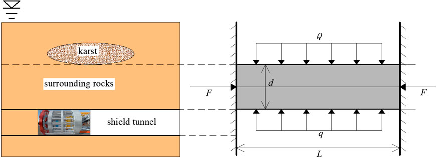
Figure 5. Mechanical model of the underwater karst located above the shield tunnel.
4.2.2 Calculation of the surrounding rock potential function
According to Reference (Jiang et al., 2005), the deflection of the beam axis shown in Figure 5 can be expressed as:m
According to Equation 13, the initial deflection of the beam axis is:
where w represents the deflection of the beam at L/2, and l denotes the arc length from the endpoint of the beam to any position along the axis.
Based on the cusp catastrophe theory of grouting reinforcement, the potential function of the surrounding rocks is:
where U represents the strain energy of the beam, Wx denotes the work done in the horizontal direction, and Wy is the work done by vertical forces.
According to the theories of material mechanics and elasticity, based on Equation 14, the terms in Equation 15 can be expressed as:
By combining Equations 15, 16, the potential function of the surrounding rocks can be obtained. After simplification, it is expressed as:
4.2.3 Control standard for grouting reinforcement
Let
Combining Equations 17, 18 yields:
Equation 19 represents the standard form of cusp catastrophe, which is consistent with Equation 12. When the bifurcation set satisfies Δ > 0, the surrounding rocks reinforced by grouting remain stable during shield tunneling. Thus, the following condition holds:
By substituting the terms from Equation 18 into Equation 20 and considering I = d3/12 and Q = Pa + Pw + P, the elastic modulus E of the surrounding rocks after grouting reinforcement can be determined. This is expressed in Equation 21, which serves as the grouting reinforcement standard for underwater karst formations located above the shield tunnel:
where
According to Equation 21, the control standard for grouting reinforcement depends on factors such as the karst distance, the properties of the surrounding rocks after reinforcement, the material performance following karst reinforcement, and the influence of groundwater.
4.3 Karst below the tunnel
When the underwater karst is positioned below the shield tunnel, the grouting-reinforced structure between the karst and the tunnel is subjected to the weight of the surrounding rocks, groundwater pressure, and the weight of the shield machinery. Under these applied loads, vertical displacement occurs in the surrounding rocks during shield tunneling. If this vertical displacement exceeds a critical threshold, instability develops in the surrounding rocks. Therefore, the grouting reinforcement standard is established to ensure that the vertical displacement of the surrounding rocks during shield tunneling remains below the instability threshold.
4.3.1 Basic assumptions and model establishment
Based on the actual site conditions, we assume that the span between karst and shield tunnel is L, the distance between the two is d, the elastic modulus of the formation after grouting reinforcement is given as E, the load of the shield machine is P1, the weight of the surrounding rocks is
Based on these assumptions, the mechanical model illustrated in Figure 6 can be established.
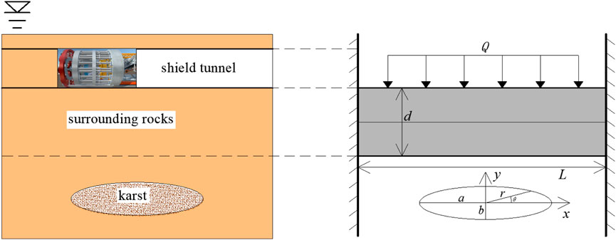
Figure 6. Mechanical model when the underwater karst is located below the shield tunnel.
4.3.2 Calculation of the surrounding rock potential function
According to References (Chen, 2002; Xu, 2024), the deflection of the fixed support beam plate shown in Figure 6 is expressed as:
where E represents the elastic modulus of the surrounding rocks after grouting reinforcement, and μ is the corresponding Poisson’s ratio.
If we let
Converting Equation 23 into a polar coordinate form, we have
where
Additionally, based on Equation 24, considering the boundary conditions and deterministic laws, the radial displacement of the surrounding rocks is given by:
According to the cusp catastrophe theory and the established model, combining Equation 25 for radial displacement of surrounding rock, the potential function of the surrounding rocks after grouting reinforcement is:
where U1 represents the bending deformation potential energy of the surrounding rocks after grouting reinforcement, U2 denotes the surface strain potential energy, W1 is the axial work done by external loads, and W2 represents the radial work done by external loads, respectively.
Based on elastic mechanics and the constructed model, it follows that:
By combining Equations 26, 27 and performing term transposition, the potential function of the surrounding rocks is obtained as:
4.3.3 Control standard for grouting reinforcement
Let
Then Equation 28 can be rewritten as,
Equation 29 represents the standard form of cusp catastrophe, which aligns with Equation 12. When its bifurcation set satisfies Δ > 0, the terms of w, A, and B are substituted into Equation 20, and considering
According to Equation 30, the control standard for grouting reinforcement depends on factors such as the karst distance, properties of the surrounding rocks after reinforcement, material performance following karst reinforcement, karst size, and the influence of groundwater.
4.4 Karst in front of the tunnel
When the underwater karst is positioned in front of the shield tunnel, the grouting-reinforced structure between the karst and the tunnel is subjected to external loads, leading to horizontal displacement of the surrounding rocks during the shield tunneling process. If this horizontal displacement exceeds a critical threshold, instability occurs in the surrounding rocks. Therefore, the grouting reinforcement standard is established to ensure that the horizontal displacement of the surrounding rocks during shield tunneling remains below the instability threshold.
4.4.1 Basic assumptions and model establishment
Based on actual site conditions, let d represent the safe distance between the karst and the shield tunnel, r denote the tunnel radius, E be the elastic modulus of the formation after grouting reinforcement, P indicate the horizontal load exerted by the karst on the tunnel face, and F represent the shield support force. The following assumptions are considered: the formation remains intact after grouting reinforcement, and the karst is positioned directly in front of the tunnel axis. Horizontal loads act uniformly on the tunnel face.
Based on these assumptions, the mechanical model illustrated in Figure 7 can be established.
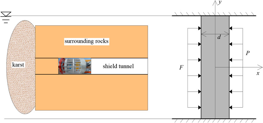
Figure 7. Mechanical model of underwater karst located in front of the shield tunnel.
4.4.2 Calculation of the surrounding rock potential function
According to the cusp catastrophe theory and the mechanical model in Figure 7, the potential function of the tunnel face after grouting reinforcement is expressed as:
where U1 and U2 represent the bending deformation potential energy and surface strain potential energy of the tunnel face after grouting reinforcement, respectively, and W1 and W2 are the axial and radial work done by external loads, respectively.
According to elastic mechanics and the constructed model, the terms in Equation 31 can be expressed as:
where
Based on elastic mechanics and the mechanical model in Figure 7, the following expression holds:
By combining Equations 32, 33 and performing term transposition, the potential function of the surrounding rocks is obtained as:
4.4.3 Control standard for grouting reinforcement
Let
Then Equation 34 can be rewritten as:
Equation 36 represents the standard form of cusp catastrophe, which is consistent with Equation 12. When the bifurcation set satisfies Δ > 0, substituting Equation 35 into Equation 20 again yields the elastic modulus E of the surrounding rocks after grouting reinforcement. This defines the grouting reinforcement standard when the underwater karst is positioned in front of the shield tunnel, as expressed in Equation 37.
According to Equation 37, the control standard for grouting reinforcement depends on factors such as the karst distance, the performance of the reinforced surrounding rocks, the support force of the shield machine, the material properties following karst reinforcement, and the karst size.
5 Conclusion and outlook
Targeting grouting projects in underwater karst shield tunnels, this study examines the instability mechanism of the surrounding rocks. A mechanical model for analyzing the grouting reinforcement range in underwater karst shield tunnels is developed based on strength theory, clarifying the reinforcement range as the karst location varies relative to the tunnel. Subsequently, grouting reinforcement control standards for different scenarios are determined using the cusp catastrophe theory. The main research conclusions are as follows:
(1) Considering the stress state variations in the surrounding rocks induced by shield tunneling, the primary causes of instability in underwater karst shield tunnels are summarized. During shield tunneling, a sudden reduction in the thickness of the surrounding rocks alters their initial constraints and boundary conditions, disrupting the original stress equilibrium and leading to stress redistribution. These changes influence the water content state and disturb the surrounding rock and soil mass, resulting in significant excavation.
(2) Based on the theory of karst grouting surrounding rock failure, a cantilever beam and plate analysis model was set for the surrounding rock between karst and tunnel. The grouting reinforcement range of underwater karst shield tunnel was determined to be mainly related to factors such as karst size, karst filling material performance, tunnel span, load on the surrounding rock between the two, surrounding rock performance, and the relative position between the karst and the tunnel.
(3) By establishing a sudden change model for the instability of surrounding rock, a calculation formula for grouting reinforcement to ensure that the surrounding rock remains stable after solidification is proposed. The control standards for grouting reinforcement of underwater karst shield tunnels are clarified to be related to karst distance, rock performance after reinforcement, shield machine support force, material properties after karst reinforcement, and karst size.
Data availability statement
The original contributions presented in the study are included in the article/supplementary material, further inquiries can be directed to the corresponding author.
Author contributions
PX: Conceptualization, Writing – review and editing, Validation, Methodology. XS: Formal Analysis, Investigation, Data curation, Software, Writing – review and editing. LC: Formal Analysis, Funding acquisition, Methodology, Writing – original draft. HS: Methodology, Writing – review and editing, Formal Analysis.
Funding
The author(s) declare that financial support was received for the research and/or publication of this article. This work was supported by the Scientific Research Project of Hunan Education Department (23B1009).
Conflict of interest
Author PX was employed by CCCC South China Construction and Development Co., Ltd. Authors XS and HS were employed by CCCC Second Harbor Engineering Company Ltd.
The remaining author declares that the research was conducted in the absence of any commercial or financial relationships that could be construed as a potential conflict of interest.
Generative AI statement
The author(s) declare that no Generative AI was used in the creation of this manuscript.
Publisher’s note
All claims expressed in this article are solely those of the authors and do not necessarily represent those of their affiliated organizations, or those of the publisher, the editors and the reviewers. Any product that may be evaluated in this article, or claim that may be made by its manufacturer, is not guaranteed or endorsed by the publisher.
References
Alija, S., Torrijo, F., and Quinta-Ferreira, M. (2013). Geological engineering problems associated with tunnel construction in karst rock masses: the case of Gavarres tunnel (Spain). Eng. Geol. 157, 103–111. doi:10.1016/j.enggeo.2013.02.010
Carpinteri, A. (2017). Structural mechanics[M]. Oxfordshire: Taylor & Francis, 12–21. doi:10.1201/9781315274454
Chen, K., Ren, S., Li, Z., Chen, Z., Yu, B., and Zhang, H. (2024). Investigation on the seepage-stress field evolution mechanism and failure process of karst tunnels in water-rich areas. Environ. Earth Sci. 83 (22), 638. doi:10.1007/S12665-024-11951-1
Chen, X. (2002). Research on instability and criteria of tunnel structures. Chengdu: Southwest Jiaotong University.
Cui, D., and Wang, Q. (2008). Exploration of shield tunneling construction technology in karst cave strata. Constr. Technol. (09), 51–53+57.
Fu, H., Di, W., Yuan, F., and Min, Z. (2020). Prediction of the collapse region induced by a concealed karst cave above a deep highway tunnel. Adv. Civ. Eng. 2020. doi:10.1155/2020/8825262
Huang, F., Zhao, L., Ling, T., and Yang, X. (2017). Rock mass collapse mechanism of concealed karst cave beneath deep tunnel. Int. J. Rock Mech. Min. Sci. 91, 133–138. doi:10.1016/j.ijrmms.2016.11.017
Jiang, D., Ren, S., Liu, X., and Liu, B. (2005). Theoretical analysis of sudden changes in stability of rock salt cavern roof [J]. Rock Soil Mech. 26 (7), 1099–1103. doi:10.16285/j.rsm.2005.07.019
Lan, X., Zhang, X., Yin, Z., Li, X., and Yang, T. (2021). Mitigation of karst tunnel water inrush during operation in seasonal variation zone: case study in nanshibi tunnel. J. Perform. Constr. Facil. 35 (3). doi:10.1061/(ASCE)CF.1943-5509.0001573
Li, L., Tu, W., Shi, S., Chen, J., and Zhang, Y. (2016). Mechanism of water inrush in tunnel construction in karst area. Geomatics, Nat. Hazards Risk 7 (Suppl. 1), 35–46. doi:10.1080/19475705.2016.1181342
Li, W., Wang, W., Li, J., and Ouyang, M. (2020). Application of TETSP in advance prediction of water and mud inrush in karst tunnel. IOP Conf. Ser. Earth Environ. Sci. 617 (1), 012008. doi:10.1088/1755-1315/617/1/012008
Liao, Y., Deng, T., Zhang, W., Zhang, C., and Xu, Z. (2022). Research on the stability and support of surrounding rock in tunnel excavation based on the sharp point mutation theory [J]. Nonferrous Met. Eng. 12 (04), 116–123. doi:10.3969/j.issn.2095-1744.2022.04.017
Liu, D., Liu, M., Sun, H., Liu, R., and Lu, X. (2024). Detection and comprehensive treatment for giant karst caves under the tunnel floor: a case study in Guangxi, China. Environ. Earth Sci. 83 (23), 650. doi:10.1007/S12665-024-11959-7
Liu, G., Peng, Y., Wu, L., Cheng, Y., Dong, D., Jia, L., et al. (2024). Stability prediction of surrounding rock in tunnel crossing fault zone based on cusp catastrophe theory. KSCE J. Civ. Eng. 28 (9), 4146–4157. doi:10.1007/S12205-024-2478-1
Ma, F. (2018). Analysis of several key technologies for shield tunnels crossing the development zone of river bottom karst caves. Railw. Stand. Des. 62 (01), 93–98. doi:10.13238/j.issn.1004-2954.201703180004
Ou, X., Ouyang, L., Zheng, X., and Zhang, X. (2024). Hydrogeological analysis and remediation strategies for water inrush hazards in highway karst tunnels. Tunn. Undergr. Space Technol. incorporating Trenchless Technol. Res. 152, 105929. doi:10.1016/J.TUST.2024.105929
Shunying, J., Yue, M., and Dzianis, M. (2024). Mechanics of materials[M]. Paris: EDP Sciences, 153–171. doi:10.1051/978-2-7598-3200-2
Su, M., Liu, Y., Xue, Y., Cheng, K., Ning, Z., Li, G., et al. (2021). Detection method of karst features around tunnel construction by multi-resistivity data-fusion pseudo-3D-imaging based on the PCA approach. Eng. Geol. 288, 106127–127. doi:10.1016/J.ENGGEO.2021.106127
Su, X., Lai, J., Ma, E., Xu, J., Qiu, J., and Wang, W. (2025). Failure mechanism analysis and treatment of tunnels built in karst fissure strata: a case study. Eng. Fail. Anal. 167 (PB), 109048. doi:10.1016/J.ENGFAILANAL.2024.109048
Xu, C. (2024). Nonlinear theory research and application of rock mass failure. Nanjing: Hohai University.
Yang, J., Zhang, C., Fu, J., Wang, S., Ou, X., and Xie, Y. (2020). Pre-grouting reinforcement of underwater karst area for shield tunneling passing through Xiangjiang River in Changsha, China. Tunn. Undergr. Space Technol. 100, 103380. doi:10.1016/j.tust.2020.103380
Yang, X., Li, Z., Liu, Z., and Xiao, H. (2017). Collapse analysis of tunnel floor in karst area based on Hoek-Brown rock media. J. Central South Univ. 24 (4), 957–966. doi:10.1007/s11771-017-3498-5
Zhang, C., Fu, J., Yang, J., Ou, X., Ye, X., and Zhang, Y. (2018). Formulation and performance of grouting materials for underwater shield tunnel construction in karst ground. Constr. Build. Mater. 187, 327–338. doi:10.1016/j.conbuildmat.2018.07.054
Zhao, R., Zhang, L., Hu, A., Kai, S., and Fan, C. (2024). Risk assessment of karst water inrush in tunnel engineering based on improved game theory and uncertainty measure theory. Sci. Rep. 14 (1), 20284. doi:10.1038/S41598-024-71214-8
Keywords: shield tunnel, underwater karst, instability of surrounding rocks, grouting reinforcement, control standard
Citation: Xu P, Song X, Cao L and Sun H (2025) Extent and control standards of grouting reinforcement for underwater karst shield tunnels. Front. Earth Sci. 13:1597575. doi: 10.3389/feart.2025.1597575
Received: 21 March 2025; Accepted: 16 May 2025;
Published: 03 June 2025.
Edited by:
Tongming Qu, Hong Kong University of Science and Technology, Hong Kong SAR, ChinaCopyright © 2025 Xu, Song, Cao, and Sun. This is an open-access article distributed under the terms of the Creative Commons Attribution License (CC BY). The use, distribution or reproduction in other forums is permitted, provided the original author(s) and the copyright owner(s) are credited and that the original publication in this journal is cited, in accordance with accepted academic practice. No use, distribution or reproduction is permitted which does not comply with these terms.
*Correspondence: Lei Cao, ODE1MTcyMjMyQHFxLmNvbQ==