 Tingkai Hou
 Zonghong Zhou1*
 Yonggang Zhang
 Jing Zhang
- 1Faculty of Land Resource Engineering, Kunming University of Science and Technology, Kunming, China
- 2Engineering Research Institute, China Construction Eighth Engineering Division Corp., Ltd., Shanghai, China
Introduction: High ground stress in deep mining operations results in rocks exhibiting mechanical properties that differ from those at shallow depths. This study conducted conventional triaxial compression (CTC) tests to elucidate themechanical behaviors of deep marble under CTC conditions.
Methods: Initially, it analyzed energy evolution of deep marble under CTC conditions and developed a damage variable (D) expression. Subsequently, we examined impacts of confining pressure (σ3) and D on dissipated energy (Wd) and Poisson’s ratio (μ′) and proposed an expression for damage energy dissipation rate (U). Finally, based on the first law of thermodynamics, we established a differential equation for energy balance that facilitated the development of a damage constitutive model (DCM) for marble under CTC conditions. This model effectively couples the internal energy and damage within the rock.
Results: The results indicated that: (1) the maximum Wd increased with increasing σ3, and the Wd experienced stages of stability, slow growth, steady growth, and slowdown. (2) At a constant σ3, the μ′ under loading conditions increased with increasing damage level. However, as rock damage intensified in the residual stage, the growth rate of μ′ slowed and subsequently stabilized. (3) The proposed model effectively captures the nonlinear characteristics of stress-strain (SS) curves for deep marble under CTC conditions during the elastic, plastic yield, instability failure, and residual stages.
Discussion: This research offers theoretical insights for stability analysis in deep mining activities.
1 Introduction
As shallow mineral resources are being exhaustively mined, mining operations worldwide are shifting to deeper levels (An and Mu, 2024; Chen et al., 2025). The effects of high ground stress, high ground temperatures, high osmotic pressure, and intense mining disturbances are becoming more pronounced. High stress can deteriorate the mechanical properties of rocks. Therefore, developing an appropriate constitutive model is essential for understanding their mechanical behavior under complex stress conditions (Zheng Z. et al., 2023; Hu et al., 2025; Bian et al., 2024; Guo and Li, 2023; Feng et al., 2024).Thereby establishing a critical theoretical foundation for stability assessment of surrounding rock in deep underground engineering, geohazard prediction, and multiphysics-coupled numerical simulations.
A damage variable that measures the degradation of the rock’s mechanical properties needs to be introduced for constructing a rock DCM (Gu et al., 2025). Subsequently, the damage variable is integrated into the rock’s constitutive relations to characterize its mechanical behavior (Li WY. et al., 2023; Wen et al., 2022; Chajed and Singh, 2024; Du et al., 2024; Lu et al., 2024). Research on rock DCMs has yielded considerable outcomes globally. Numerous scholars have recognized the challenge of directly measuring damage variables and have opted to define them using externally measurable parameters. Pan et al. (2022) characterized the rock damage via the phenomenological theory. They developed a DCM for the rock sample containing a single crack under uniaxial compression by combining Weibull distribution with fracture mechanics. Cheng et al. (2025a) proposed a rock statistical damage constitutive model based on quantitative energy conversion Based on CT scanning and digital imaging technique, Wu et al. (2022) proposed a new damage variable using the fracture area projection method to develop an innovative DCM. However, these damage definition methods heavily rely on technological measurements, whose accuracy significantly influences damage calculations, thereby limiting the applicability of the models. Consequently, some researchers have incorporated theories from plastic mechanics, fracture mechanics, and statistics into damage evolution models. Chen et al. (2019) introduced a thermal damage variable to develop a statistical DCM. Zheng F. et al. (2023) introduced the Weibull distribution along with temperature, cushion, and load-coupled damage variables to establish a statistical DCM for high-temperature layered rocks. Given that the damage and failure processes in deep rocks involve continuous energy transformation and dissipation (Yang Jian et al., 2024; Yang K. et al., 2024; Li YQ. et al., 2023; Wang et al., 2023), defining damage variables from an energy perspective and developing constitutive models can fundamentally elucidate the mechanisms of rock damage evolution (Yang J. et al., 2024; Li and Guo, 2023; Lv et al., 2024). Significant advancements have also been made in deriving constitutive models based on energy considerations. Fu et al. (2025) defined a damage variable for layered rocks based on the energy dissipation principle and proposed a DCM. Likewise, Li YB. et al. (2023) and Luo and Wang (2023) developed a novel DCM for rocks under triaxial compression by integrating energy conversion principles with the mechanical properties of rocks. Nevertheless, shortcomings still exist in constitutive models developed from an energy perspective. For example, Cheng et al. (2025b) and Wang et al. (2022); Cheng et al. (2025c) only introduced the concept of energy without establishing a direct mathematical relationship between damage variables and energy. Few studies have directly solved energy differential equations to develop constitutive models.
Based on the theoretical framework of fundamental thermodynamic laws, this study establishes the quantitative coupling relationship between damage evolution and energy dissipation by dynamically embedding the damage variable D into the thermodynamic equilibrium equations under the constraint of energy conservation principles. This approach not only elucidates the intrinsic mechanisms of progressive rock failure from the perspective of energy-driven dynamics but also achieves rigorous mathematical derivation of the DCM. First, the energy evolution of deep marble under CTC conditions was analyzed using experimental data, and a damage variable (D) expression was proposed. Subsequently, the impacts of σ3 and D on Wd and μ were examined, and a mathematical expression for the U was developed. Finally, the deep marble system was treated as a thermodynamic system, and a differential equation for energy balance was established based on the principle of energy conservation under static assumptions. The coupled equations were solved to determine rock damage, strain, and stress. resulting in the development of a DCM for rocks under CTC conditions. This model was validated using experimental data. Research on rock constitutive models provides critical theoretical support for stability analysis of surrounding rock in deep engineering projects, geohazard prediction, and multiphysics-coupled numerical simulations, while advancing the transition of rock mechanics from empirical estimation to multiscale precision prediction.
2 Experiment preparation and procedure
2.1 Sample preparation
The marble was sourced from Liyang, Hunan Province, China. The sample composition includes the percentage of calcite (CaCO3) content (98%), dolomite (CaMg (CO3) 2) content (1.5%), and trace quartz (SiO2). It has a fine and smooth texture with uniformly small particles. The marble was processed into cylindrical samples measuring 50 mm in diameter and 100 mm in height with a parallelism tolerance of ±0.3%. Samples meeting the experimental accuracy were selected using wave speed testing and density calculations, as illustrated in Figure 1.
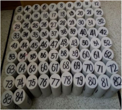
Figure 1. Selected samples.
2.2 Experimental procedure
The testing equipment employed the MTS815 triaxial rock testing system at Central South University, as depicted in Figure 2. Based on the deep geological environment where the marble is located, the confining pressure levels for the conventional triaxial tests were set at 10 MPa, 20 MPa, 30 MPa, 40 MPa, and 50 MPa, respectively.
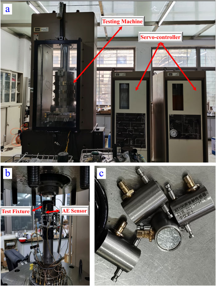
Figure 2. Testing equipment. (a) Experimental equipment (b) Enlarged view of rocksample loading (c) Enlarged view of sensor.
The experimental procedure is outlined as follows:.
(1) The σ2 = σ3 was gradually increased to 10 MPa, 20 MPa, 30 MPa, 40 MPa, and 50 MPa, respectively, at a loading rate of 0.1 MPa/s in a stress-controlled manner under hydrostatic pressure conditions.
(2) σ3 was maintained for 10 s. Subsequently, the axial pressure was gradually increased until the rock sample failed. The stress path is presented in Figure 3.
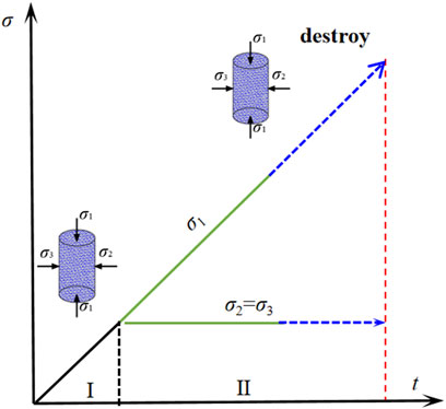
Figure 3. Loading path for conventional triaxial test.
The SS curves for rock samples under various σ3 are presented in Figure 4a, where the x-axis represents axial strain (ε1) and the y-axis indicates axial stress (σ1). As shown in Figure 4b, the microscopic characteristics of the rock samples when the peripheral pressure of the marble is 30 MPa, when the rock samples are damaged. The main rupture surface is dominated by along-crystal fracture, the angularity of the rupture surface is relatively sharp, high and low, in the shape of a step, the crystal fracture forms a confluence, the tendency of the fracture is randomly distributed without an obvious pattern, and under high magnification, it can be seen that the rupture surface has an obvious shear damage feature, and locally there is a tensile rupture surface developed at the same time, which exhibits a shear and tensile composite damage feature.
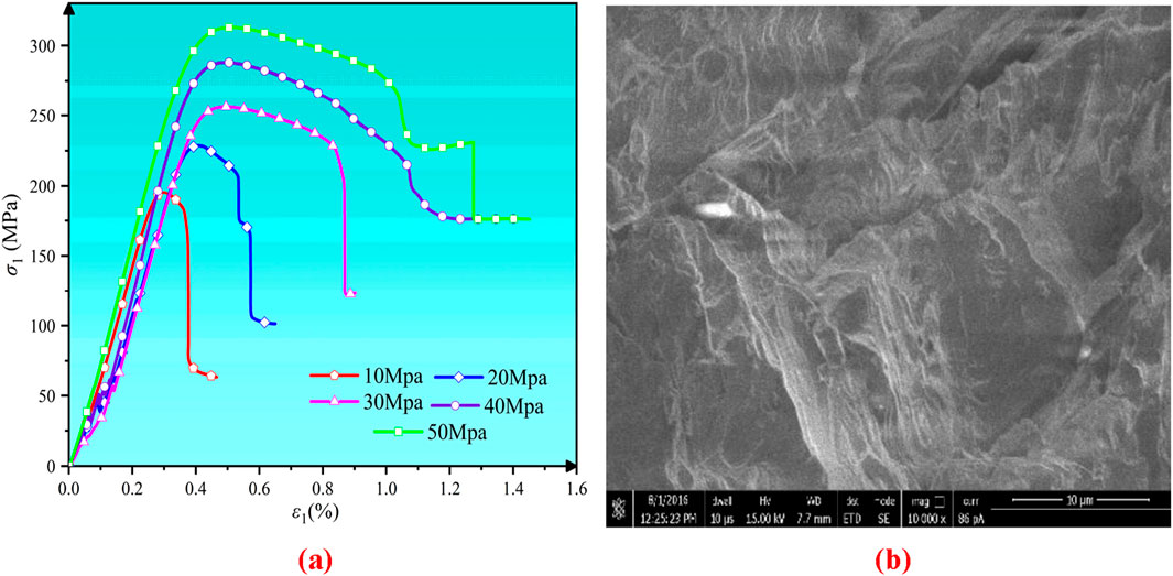
Figure 4. (a) SS curves obtained from CTC tests. (b) Scanned image of rupture surface electron microscope at 30 MPa circumferential pressure.
3 Energy evolution of samples under CTC conditions
3.1 Energy calculation based on experimental data
The generation and propagation of microcracks in rock consume energy. Thus, rock deformation involves complex energy transformations. The amount of energy dissipated reflects the degree of reduction in the rock’s original strength. As depicted in Figure 5, the areas enclosed by OABCDE, OABCN, CMN, CDEM, and PQM represent the total work done by external forces (W), the dissipated energy before the peak, the stored elastic strain energy before the peak, the dissipated energy after the peak, and the residual strain energy after the peak, respectively.
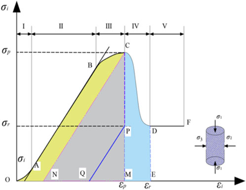
Figure 5. Energy relationships during loading and unloading.
According to the energy conservation principle, the rock sample can be considered a closed system where the W is equal to the sum of the elastic energy stored in the rock and the total energy released (Yan et al., 2023; Feng et al., 2023), as expressed in Equation 1:
Where W represents the total work done by external forces on the rock sample under any strain ε, We corresponds to the recoverable elastic energy stored by the rock in this strain state, and Wd characterizes the energy dissipated by the rock due to the evolution of the damage.
Based on relevant research findings (Zhang et al., 2023; Liu and Gu, 2024), the W and We under CTC conditions can be expressed as:
where
Under conventional triaxial conditions, the intermediate and minimum principal stresses of the rock sample satisfy:
Equation 2 can be simplified to:
Based on Equation 1, the Wd can be expressed as:
A combination of Equations 1–3 allows for the calculation of the Wd of the rock sample under CTC conditions.
3.2 Analysis of energy evolution
The evolution of W, We, and Wd for marble sample under CTC conditions at varying σ3 was derived from experimental data, as illustrated in Figure 6.
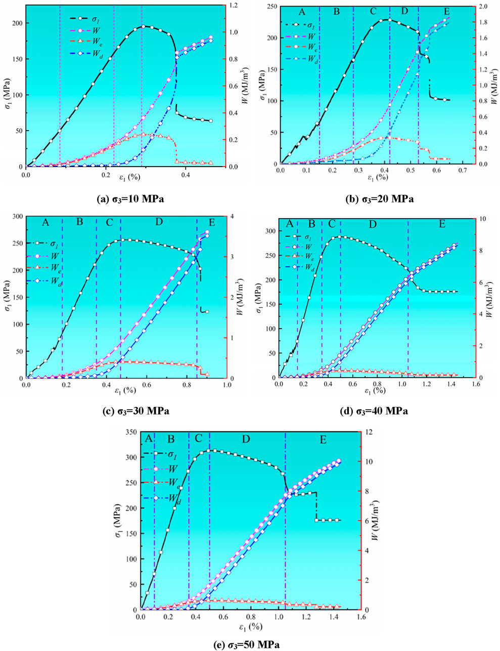
Figure 6. (a) σ3 = 10 MPa. (b) σ3 = 20 MPa. (c) σ3 = 30 MPa (d) σ3 = 40 MPa. (e) σ3 = 50 MPa. Energy evolution curves under CTC tests.
Experimental analysis reveals that the enhancement effect of confining pressure (σ3) significantly governs the energy evolution mechanisms in rocks. As the confining pressure increases from 10 MPa to 50 MPa, the total energy density input by external loads exhibits nonlinear growth characteristics, reaching 0.965 MJ/m3, 1.859 MJ/m3, 3.615 MJ/m3, 8.478 MJ/m3, and 9.275 MJ/m3 respectively. This progression aligns with the exponential evolution trend of total energy (W) under elevated confining pressures. Energy partitioning features demonstrate: 1) The maximum stored elastic energy (We) shows a stepwise increase with confining pressure gradients, achieving peak values of 0.345 MJ/m3, 0.387 MJ/m3, 0.406 MJ/m3, 0.434 MJ/m3, and 0.626 MJ/m3 at corresponding pressure levels; 2) The dissipated energy during failure (Wd) displays accelerated growth, with measured values of 0.939 MJ/m3, 1.795 MJ/m3, 3.518 MJ/m3, 8.313 MJ/m3, and 8.920 MJ/m3. These energy evolution patterns indicate that confining pressure not only enhances the energy storage capacity of rock media (manifested by an 81.4% increase in We) but also promotes energy accumulation through restrained crack propagation, ultimately resulting in up to 8.5-fold intensification of energy release (Wd) at failure. This energy conversion mechanism fundamentally explains the energy-driven nature of engineering disasters in rock masses under deep high-stress environments.
The analysis revealed that the energy evolution can be categorized into five stages:
(A) Compaction Stage: W, We, and Wd all increased slowly with increasing σ1 and ε1. This suggested that during the compaction stage, the marble sample experienced energy dissipation as a result of microcrack closure.
(B) Linear elastic stage: W and We exhibited a distinct upward concave growth at an increasing rate, while Wd remained relatively constant. This indicated that as σ1 increased, the micro-cracks within the marble gradually closed, resulting in all input energy being stored as elastic energy with negligible loss.
(C) Plastic yield stage: As σ1 increased, the SS curve showed a nonlinear growth. W, We, and Wd all increased gradually with increasing σ1. However, the rate of increase in Wd began to accelerate while the rate of increase in We decreased. A detailed analysis revealed that micro-cracks started to initiate and expand within the marble sample, resulting in most of the input energy being converted into Wd.
(D) Instability failure stage: The micro-cracks within the marble sample began to interconnect, forming a macroscopic fracture surface. We was rapidly converted into Wd, which was manifested by the increase in W and Wd, as well as a gradual decrease in We.
(E) Residual strength stage: As the macroscopic fracture surface developed, the strength of the sample diminished. The rate of increase in W and Wd slowed down, while We continued to decline.
4 Development of a DCM based on energy balance
4.1 Fundamental equations for the model
4.1.1 Definition of the damage variable
Previous analysis of energy evolution revealed that the proportion of Wd reflects the transition of rock damage from intact to complete failure. Therefore, a new method was introduced to define the damage variable in terms of cumulative dissipated energy.
where D represents the damage variable; Wd denotes the dissipated energy for any given strain ε; and Wdm is the cumulative dissipated energy required for complete failure of the sample.
D = 0 indicates that the rock is intact and undamaged, while D = 1 indicates that the rock completely fails. However, the rock under CTC conditions still retains some We and load-bearing capacity in the residual stage. Therefore, a correction factor γ related to residual strength is introduced and defined as:
where σc represents the peak compressive strength of the rock under CTC conditions, and σr denotes the residual strength.
Modify the damage variable D, as defined in Equation 5, based on Equation 6.
Numerous scholars frequently employ the degree of degradation in the elastic modulus to characterize the damage of rock masses (Liu et al., 2024). This study followed this approach and calculated the elastic modulus under damaged conditions via Equations 7. As shown in Equation 8:
where E represents the elastic modulus after damage, and E0 denotes the initial elastic modulus.
4.1.2 Assumptions on strain
It is assumed that both the axial and circumferential strains consist of two components: elastic strain εe and plastic strain εp (Zhou et al., 2019). The expression for the strain is as follows:
where ε signifies the strain tensor; εe and εp denote the elastic and plastic strain tensors, respectively.
When differentiating the axial and circumferential strains, it is assumed that the strain increment includes both elastic and plastic components, as expressed in Equation 10.
where d denotes the differential operator.
4.1.3 Equation for SS relationship
According to Hooke’s Law, the SS equation for rocks under CTC conditions can be expressed as:
where σ represents the stress tensor under CTC conditions; M0 is the initial stiffness matrix for the undamaged rock; and γ is the correction factor, as illustrated in Equation 6.
The expression for the M0 is given by:
where μ is the Poisson’s ratio.
In CTC tests, the W includes two components: one from σ1 and the other from intermediate and minimum principal stresses. According to the stress conditions of the rock, it is known that σ2 = σ3.
By combining Equations 11, 12, the SS relationship for the rock under CTC condition can be simplified as Equation 13:
where η and β as shown in Equation 14
4.2 Damage evolution equation under CTC conditions
For any infinitesimal element of rock, it is assumed that the compression process involves only energy exchange with the surroundings. The incremental form of the law of conservation of energy is expressed as (Qu et al., 2023):
Regarding the work done by an infinitesimal element, the differential equation for energy balance under triaxial stress conditions comprises three components:
(1) Differential form of W
Under conventional triaxial compression conditions, the differential form of work done by external forces can be expressed as:
where
(2) Increment of We
Under CTC conditions, the We stored in the rock can be expressed as:
By differentiating Equation 17, the increment of We can be obtained:
(3) Increment of Wd
According to thermodynamic principles, D is closely related to Wd. Analogous to temperature and entropy, we introduced a variable: the damage energy dissipation rate U, which represents the energy required for a one-unit increase in the D as the rock transitions from an intact state to failure. The Wd can be expressed as the product of the U and the D:
where U denotes the damage energy dissipation rate, with a unit of MJ/m3. Converting Equation 19 to Equation 20
Substituting Equations 16, 18 and 19 into differential equation for energy balance Equation 15 yields:
Equation 21 is a universal expression. To characterize the damage evolution of specific rock materials, further determination of the plastic strain increment and U is necessary.
4.3 Expression for U
Despite Equation 21, it is essential to provide an expression for the U. Based on the methods for calculating Wd (Equations 3, 4) and the definition of the D (Equation 7), U is derived through experimental data.
Figure 7 illustrates the Wd versus ε1 curves for rocks under different σ3. Figure 7 revealed that the variation patterns of Wd are consistent under different σ3, and the maximum Wd increased as the σ3 increased. The evolution of Wd experienced four stages with increasing axial strain: stability, slow growth, steady growth, and slowdown.
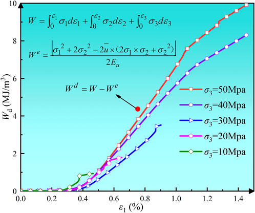
Figure 7. Relationship between ε1 and Wd.
A combination of Equations 2, 4, 7 enables the calculation of the D during the conventional triaxial loading process. The resulting relationship between D and ε1 is depicted in Figure 8.
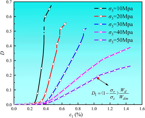
Figure 8. Relationship between ε1 and D.
Figure 8 illustrated that the damage evolution process can be categorized into three stages: stability, accelerated growth, and slow growth. The marble sample experienced a sharp increase in D during the plastic yield and instability failure stages. As it entered the residual stress stage, the growth rate of damage diminished.
Figure 9 illustrates the relationship between Wd and D, where the x-axis and y-axis represents the D and Wd, respectively.
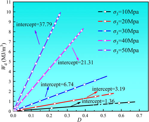
Figure 9. Relationship between D and Wd.
A clear positive correlation was identified between Wd and D. Moreover, growth rate of Wd varied under different σ3, and a higher σ3 led to a greater growth rate. This behavior can be attributed to the inherent density of marble. In deep and high confining pressure environments, the Wd absorbed per unit damage remained stable and uniform as the σ1 increased.
Figure 9 showed that Wd is significantly influenced by both the D and σ3, with higher σ3 leading to greater Wd. Based on this observation, a model was constructed to characterize the magnitude of the U:
where U0 represents the damage energy dissipation rate at zero σ3, which characterizes the inherent properties of the rock material; K denotes the influence coefficient of σ3 and D on the U.
The U values under different σ3 are summarized in Table 1.
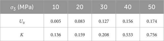
Table 1. Summary of U values under various σ3.
The approach for determining the U0 and K of σ3 and D in Equation 22 is as follows.
The Wd corresponding to each D of the rock during the CTC was computed using Equations 2–4, 7. A scatter plot was generated with Wd on the vertical axis and D on the horizontal axis.
Based on the scatter distribution characteristics of Wd versus D in Figure 9, Pearson correlation analysis was used to show a significant positive linear correlation (r = 0.92, p < 0.001). To further quantify the relationship, we used OriginPro 2022 to fit a least-squares linear regression to the experimental data to obtain the corresponding functional expression. The slope of the line represents the value of Kσ3. Dividing this value by the corresponding σ3 yields the K of D and σ3 on U. The y-intercept of the line indicates the U0.
4.4 Expression for Poisson’s ratio
According to the theory of elasticity, the standard μ does not accurately represent the relationship between lateral strain and axial strain after the peak stress. Therefore, this study introduced a new Poisson’s ratio, denoted as μ′, to characterize the relationship between lateral and axial strains throughout the entire SS process of the rock.
μ′ was computed for deep marble under different σ3 using Equation 23. The evolution curves of μ′ in relation to the D and ε1 are illustrated in Figures 10, 11, respectively, where the x-axis indicates the D or ε1, while the y-axis represents the μ’.

Figure 10. ε1 versus μ′ curve.
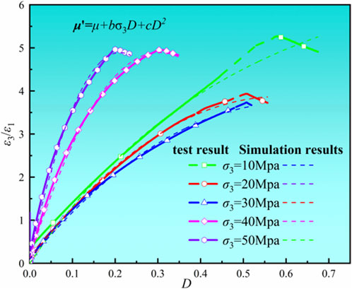
Figure 11. D versus μ′ curve.
A thorough analysis revealed that σ3 and D are significant factors influencing the evolution of μ’. The σ3 suppressed the increases in circumferential strain and μ′ of the rock. When the σ3 was held constant, μ′ increased with increasing D. As rock damage in the residual stage intensified, the growth rate of μ′ decreased and subsequently stabilized.
Figure 11 indicated that μ′ exhibits an approximately quadratic relationship with the D. To emphasize the influence of σ3 on μ′, a binomial function was employed to define μ’:
where μ represents the Poisson’s ratio for intact rock (when the damage variable is 0); b denotes the combined influence coefficient of the D and σ3; and c signifies the influence coefficient of the D.
Additionally, we employed the least squares method to ascertain the parameters in Equation 24, with the fitting results depicted by the solid line in Figure 11. The average goodness of fit (R2) was 0.995, which indicated that the fitting results effectively reflect the relationship among μ′, σ3, and D. The parameter values and goodness of fit under different σ3 are summarized in Table 2.
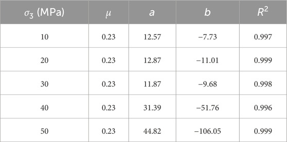
Table 2. Parameter values and goodness of fit under different σ3.
4.5 Expression for plastic strain
Based on the strain assumptions of Equation 9 and the principle of strain equivalence, the expressions related to the damage variable were employed to characterize the relationships between elastic and plastic strains and macroscopic strain, as shown in Equation 25:
Equation 26 was derived by differentiating the axial elastic strain ε1e and the circumferential elastic strain ε3e with respect to D.
Substituting Equation 26 into Equation 10 yields the expression for axial plastic strain:
Equation 24 defines the expression for the
The increment of circumferential strain can be expressed as Equation 29:
Similarly, the increment of circumferential plastic strain can be expressed as:
4.6 Solution of the constitutive model
In CTC tests, the constant σ3 results in a stress increment of 0 (i.e.,
Equations 10, 19, 27, 30, 31 are combined and represented in a matrix form, as expressed in Equation 32.
Applying Gaussian elimination to Equation 32 yieldsEquation 33
5 Results and analysis
Equation 21 was incorporated into the SS constitutive relation, which was subsequently iterated using the Euler method to derive the complete SS curves for rock under various σ3, as illustrated in Figure 12, These curves were then compared with experimental data for marble.
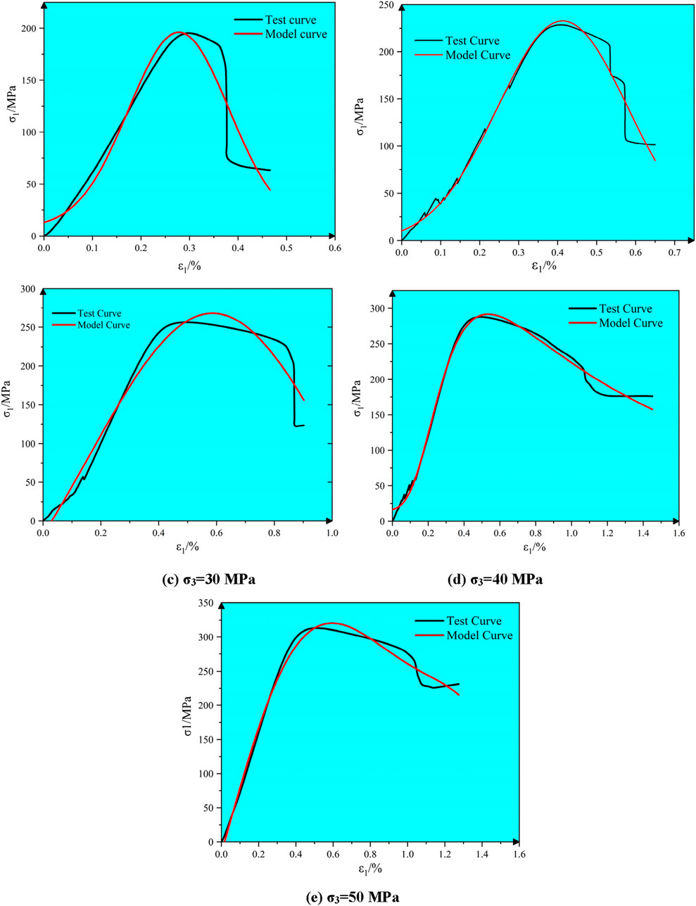
Figure 12. (a) σ3 = 10 MPa. (b) σ3 = 20. (c) σ3 = 30 MPa. (d) σ3 = 40 MPa. (e) σ3 = 50 MPa. MPaComparison of theoretical and experimental curves under different σ3.
The established equilibrium differential equations in this study quantitatively account for the effects of σ3 and damage on the U and μ’. Therefore, the proposed constitutive model effectively captures the evolution of complete SS curves for deep marble under CTC conditions during the elastic, plastic yield, instability failure, and residual strength stages. Furthermore, the curves resulting from this constitutive model are continuous and closely align with actual data.
6 Conclusion
This study analyzed the energy evolution of marble under CTC conditions and proposed a new expression for the damage variable from the perspective of energy dissipation. The expressions for U and μ′ were established based on the data derived from CTC tests. A DCM was established using the differential equation for energy balance, and the model parameters were calibrated. The following conclusions are drawn:
(1) The Wd curve experienced stages of stability, slow growth, steady growth, and slowdown. The maximum Wd increased with rising σ3.
(2) The increase in σ3 inhibited the growth of rock damage. When the σ3 was held constant, μ′ increased with the degree of damage. As rock damage in the residual stage intensified, the growth rate of μ′ decreased and subsequently stabilized.
(3) The energy release rate U demonstrates a significant positive correlation with confining pressure σ3, revealing that under high confining pressure conditions, rock exhibits enhanced energy dissipation characteristics at equivalent damage levels: As σ3 increases, the dissipated energy Wd released during failure intensifies markedly, thereby driving systematic growth in U values. This correlation validates the physical mechanism whereby confinement effects promote energy accumulation through suppressing disordered crack propagation.
(4) A comparison between the experimental data and model predictions indicated that the proposed constitutive model accurately captures the elastic stage, plastic yield stage, instability failure stage, and the nonlinear characteristics of the SS curves for rock under residual strength.
Data availability statement
The original contributions presented in the study are included in the article/Supplementary Material, further inquiries can be directed to the corresponding author.
Author contributions
TH: Conceptualization, Validation, Formal Analysis, Methodology, Writing – original draft, Writing – review and editing, Data curation, Software. ZZ: Supervision, Conceptualization, Writing – review and editing, Project administration. YZ: Writing – review and editing, Validation, Conceptualization, Methodology. JZ: Methodology, Writing – review and editing, Investigation, Software, Validation.
Funding
The author(s) declare that financial support was received for the research and/or publication of this article. This work was supported by grants from the National Natural Science Foundation of China (Grant no. 51864023), the National Natural Science Foundation of China (Grant no. 52264019), the Yunnan Major Scientific and Technological Projects (Grant no. 202202AG050014) and the Youth Project of Yunnan Province Basic Research Program(202401AU070175) is gratefully acknowledged.
Conflict of interest
Author YZ was employed by China Construction Eighth Engineering Division Corp., Ltd.
The remaining authors declare that the research was conducted in the absence of any commercial or financial relationships that could be construed as a potential conflict of interest.
Generative AI statement
The author(s) declare that no Generative AI was used in the creation of this manuscript.
Publisher’s note
All claims expressed in this article are solely those of the authors and do not necessarily represent those of their affiliated organizations, or those of the publisher, the editors and the reviewers. Any product that may be evaluated in this article, or claim that may be made by its manufacturer, is not guaranteed or endorsed by the publisher.
References
An, H. M., and Mu, X. H. (2024). Contributions to rock fracture induced by high ground stress in deep mining: a review. Rock Mech. Rock Eng. 58 (1), 463–511. doi:10.1007/s00603-024-04113-z
Bian, K., Chen, Y. N., Zhang, W., Xiong, Q. R., and Li, B. (2024). Mechanical property deterioration and a full-stage constitutive model of shale subject to water-softening effect. Bull. Eng. Geol. Environ. 83 (11), 475. doi:10.1007/s10064-024-03957-7
Chajed, S., and Singh, A. (2024). Acoustic emission (AE) based damage quantification and its relation with AE-based micromechanical coupled damage plasticity model for intact rocks. Rock Mech. Rock Eng. 57, 2581–2604. doi:10.1007/s00603-023-03686-5
Chen, Q. G., Zuo, Y. J., and Zheng, L. J. (2025). Deformation failure mechanism and stability-control technology of deep layered clastic-rock roadway under dynamic disturbance. Tunn. Undergr. Space Technol. incorporating Trenchless Technol. Res. 156, 156106255–106255. doi:10.1016/J.TUST.2024.106255
Chen, X. X., He, P., Qin, Z., Li, J., and Gong, Y. (2019). Statistical damage model of altered granite under dry-wet cycles. Symmetry, 11(1):41. doi:10.3390/sym11010041
Cheng, H. M., Yang, X. B., Lu, J., Dong, C. L., and Lan, Y. Q. (2025a). Statistical damage constitutive model based on energy conversion for rocks. Int. J. Damage Mech. 34 (1), 186–210. doi:10.1177/10567895241277217
Cheng, H. M., Yang, X. B., Lu, J., Dong, C. L., and Yongqing, L. (2025b). Statistical damage constitutive model based on energy conversion for rocks. Int. J. Damage Mech. 34 (1), 186–210. doi:10.1177/10567895241277217
Cheng, H. M., Yang, X. B., Lu, J., Dong, C. L., and Yongqing, L. (2025c). Statistical damage constitutive model based on energy conversion for rocks. Int. J. Damage Mech. 34 (1), 186–210. doi:10.1177/10567895241277217
Du, K., Yi, Y., Luo, X. Y., Liu, K., Li, P., and Wang, S. f. (2024). Novel damage constitutive models and new quantitative identification method for stress thresholds of rocks under uniaxial compression. J. Cent. South Univ. 31, 2658–2675. doi:10.1007/s11771-024-5725-1
Feng, J. W., Liu, S. Z., Du, H., and Liu, H. (2023). Quantitative prediction of ultra-deep tight sandstone fractures based on the theory of minimum energy dissipation. Geoenergy Sci. Eng. 226, 211749. doi:10.1016/j.geoen.2023.211749
Feng, Q., Xu, J., Cai, C., Liu, W., Jin, J., Han, W., et al. (2024). Damage constitutive model and meso-failure characteristics of freeze–thaw rock under triaxial compression. Bull. Eng. Geol. Environ. 83, 112. doi:10.1007/s10064-024-03594-0
Fu, J. J., Wang, Z. L., Wang, J. G., Feng, C. C., and Li, S. (2025). The energy evolution and constitutive model of layered rock at medium and high strain rates. Environ. Earth Sci. 84 (3), 93. doi:10.1007/s12665-024-12052-9
Gu, Q. X., Zhang, Q., Dai, W. L., Quan, X. W., Ye, S. Z., and Li, T. (2025). A novel statistical damage constitutive model of rock joints considering normal stress and joint roughness. Int. J. Damage Mech. 34 (2), 326–351. doi:10.1177/10567895241277681
Guo, C. G., and Li, J. (2023). A Unified concrete damage model for monotonic loading and fatigue loading. ce/papers 6 (5), 1252–1257. doi:10.1002/cepa.2169
Hu, J. Y., Sheng, D. F., Qin, F. F., Zhu, Y. C., Li, Z. H., Chen, T. C., et al. (2025). Progressive failure characteristics and damage constitutive model of fissured rocks under water–rock coupling. Theor. Appl. Fract. Mech. 135, 135104765–104765. doi:10.1016/j.tafmec.2024.104765
Li, J., and Guo, C. (2023). A unified stochastic damage model for concrete under monotonic and fatigue loading. Int. J. Fatigue 175, 107766. doi:10.1016/j.ijfatigue.2023.107766
Li, W. Y., Fang, S. Z., Gao, X., and Han, Y. (2023a). Method of defining rock damage variable on the basis of wave impedance. Energy Sci. & Eng. 11 (10), 3641–3661. doi:10.1002/ese3.1544
Li, Y. B., Zhai, Y., Xie, Y. F., and Meng, F. (2023c). Research on the impact mechanical properties of real-time high-temperature granite and a coupled thermal-mechanical constitutive model. Mater. Basel, Switz. 16 (7), 2773. doi:10.3390/ma16072773
Li, Y. Q., Huang, D., and He, J. (2023b). Energy evolution and damage constitutive model of anchored jointed rock masses under static and fatigue loads. Int. J. Fatigue 167, 107313. doi:10.1016/J.IJFATIGUE.2022.107313
Liu, B., Zhu, L., Liu, X. W., Liu, Q. S., Fan, Y., Yao, W. J., et al. (2024). Energy evolution and damage deformation behavior of cemented broken coal specimen under triaxial compression condition. Energy 310, 310133203–133203. doi:10.1016/J.ENERGY.2024.133203
Liu, Z. X., and Gu, Q. H. (2024). Strain energy density evolution in sandstone under true triaxial compression at different loading rates. Geotechnical Geol. Eng. 43 (1), 20. doi:10.1007/S10706-024-03018-6
Lu, T. C., Wu, H., Yin, S. M., and Xu, X. (2024). Study of rock damage constitutive model considering temperature effect based on Weibull distribution. Appl. Sci. 14 (9), 3766. doi:10.3390/app14093766
Luo, J. A., and Wang, L. L. (2023). Study on energy evolution and damage constitutive model of sandstone under cyclic loading and unloading. Appl. Sci. 13 (3), 1690. doi:10.3390/app13031690
Lv, H. M., Yang, X. C., Yu, Y., and Liu, W. (2024). Research on rock energy constitutive model based on functional principle. Symmetry 16 (9), 1250. doi:10.3390/sym16091250
Pan, J. L., Cai, M. F., Li, P., and Guo, Q. f. (2022). A damage constitutive model of rock-like materials containing a single crack under the action of chemical corrosion and uniaxial compression. J. Central South Univ. 29 (2), 486–498. doi:10.1007/s11771-022-4949-1
Qu, X., Wang, H. L., Xie, W. C., and Ma, H. (2023). Experimental investigation on dynamic compressive mechanical properties of weathered granite and statistical damage constitutive model. Bull. Eng. Geol. Environ. 82 (8), 313. doi:10.1007/s10064-023-03326-w
Wang, X. L., Zhang, J. H., Qian, L., Yao, T. Z., Mo, Z. G., He, J. H., et al. (2022). Nonlinear statistical damage constitutive model of granite based on the energy dissipation ratio. Sci. Rep. 12 (1), 5460. doi:10.1038/s41598-022-09503-3
Wang, Z. H., Li, B. B., Ren, C. H., Li, J. H., Cheng, Q., Wu, X., et al. (2023). Energy-driven damage constitutive model of water-bearing coal under triaxial compression. Rock Mech. Rock Eng. 57 (2), 1309–1328. doi:10.1007/s00603-023-03592-w
Wen, L., Huang, Y., Wen, J. X., Zhang, X., and Lu, W. q. (2022). A comparative study on damage variable and geo-mechanical properties of the pre-damaged rock specimen. Adv. Civ. Eng. 2022. doi:10.1155/2022/3583754
Wu, L. Y., Wang, Z., Ma, D., Zhang, J. w., Wu, G., Wen, S., et al. (2022). A continuous damage statistical constitutive model for sandstone and mudstone based on triaxial compression tests. Rock Mech. Rock Eng. 55, 4963–4978. doi:10.1007/s00603-022-02924-6
Yan, B. Q., Kang, H. P., Zuo, J. P., Wang, P. T., Li, X. S., Cai, M. F., et al. (2023). Study on damage anisotropy and energy evolution mechanism of jointed rock mass based on energy dissipation theory. Bull. Eng. Geol. Environ. 82 (8), 294. doi:10.1007/s10064-023-03278-1
Yang, J., Yang, X. B., Yin, S. H., Zhang, X. Z., Li, G. C., Chen, X., et al. (2024a). Damage characteristics and constitutive model of magnesium slag-based cemented backfill based on energy dissipation. Constr. Build. Mater. 449, 449138443–138443. doi:10.1016/j.conbuildmat.2024.138443
Yang, J., Yang, X. B., Yin, S. H., Zhang, X. Z., Li, G. C., Chen, X., et al. (2024c). Damage characteristics and constitutive model of magnesium slag-based cemented backfill based on energy dissipation. Constr. Build. Mater. 449, 449138443–138443. doi:10.1016/j.conbuildmat.2024.138443
Yang, K., Yan, Q. X., Zhang, C., and Cheng, Y. Y. (2024b). Investigation of energy transformation and dissipation in soft rock tunnels with yielding support under large deformation. Rock Mech. Rock Eng. 57 (8), 6119–6140. doi:10.1007/S00603-024-03842-5
Zhang, P. L., Gong, F. Q., Luo, S., Si, X. F., and Xu, L. (2023). Damage constitutive model of uniaxially compressed coal material considering energy dissipation. J. Mater. Res. Technol. 27, 27920–27931. doi:10.1016/j.jmrt.2023.09.281
Zheng, F., Jiang, A. A., Jiang, T. F., Jiang, H. P., and Guo, X. (2023b). Study on mechanical characteristics and damage model of layered sandstone after high temperature action. Case Stud. Constr. Mater. 19, e02601. doi:10.1016/j.cscm.2023.e02601
Zheng, Z., Su, H., Wang, W., Wang, Z. C., Liu, Z. B., He, B. G., et al. (2023a). A new hydro-mechanical coupling constitutive model for brittle rocks considering initial compaction, hardening and softening behaviors under complex stress states. Geomechanics Geophys. Geo-Energy Geo-Resources 9 (1), 68. doi:10.1007/S40948-023-00607-2
Keywords: rock mechanics, energy dissipation, triaxial compression, damage variable, constitutive model
Citation: Hou T, Zhou Z, Zhang Y and Zhang J (2025) Energy evolution and damage constitutive model for deep marble under triaxial compression. Front. Earth Sci. 13:1600846. doi: 10.3389/feart.2025.1600846
Received: 27 March 2025; Accepted: 18 April 2025;
Published: 30 April 2025.
Edited by:
Wenling Tian, China University of Mining and Technology, ChinaReviewed by:
Feng Jiang, Shandong University of Science and Technology, ChinaYuan Cui, Tsinghua University, China
Copyright © 2025 Hou, Zhou, Zhang and Zhang. This is an open-access article distributed under the terms of the Creative Commons Attribution License (CC BY). The use, distribution or reproduction in other forums is permitted, provided the original author(s) and the copyright owner(s) are credited and that the original publication in this journal is cited, in accordance with accepted academic practice. No use, distribution or reproduction is permitted which does not comply with these terms.
*Correspondence: Zonghong Zhou, emhvdTIwMDUxMDAxQDE2My5jb20=