 Meng Tu1
 Lin Yang
- 1Wenshan Tianwen Expressway Investment and Development Co., Ltd., Wenshan, China
- 2CCCC Rail Transit Branch, Beijing, China
- 3CCCC Second Harbor Engineering Co., Ltd., Wuhan, China
Introduction: In drill-and-blast excavation for small- and medium-sized tunnels, the conventional wedge-cut blasting method is often constrained by the limited maneuvering space of construction equipment. This restriction can result in excessive inclination of wedge-cut holes relative to the tunnel face. Consequently, the rock in the cut zone is subjected to strong confinement, leading to reduced advance per round, low blasthole utilization efficiency, and an increased specific charge.
Methods: In this study, theoretical analysis and formula derivation were conducted to evaluate the respective advantages and limitations of wedge cutting and straight-hole cutting. Based on these analyses, optimal layout parameters for straight holes were determined. A combined short straight-hole + wedge compound cut blasting scheme was subsequently proposed and tested in a hard rock tunnel.
Results: When calculating the spacing between charge holes and relief holes, the influence of high strain rates on the rock’s tensile strength should be incorporated to ensure that theoretical parameters are both accurate and applicable. Compared with the original blasting scheme, the designed compound cut method increased the advance per round from 1.7–1.8 m to 2.0–2.1 m and improved blasthole utilization from 73.91%–78.26% to 86.96%–91.30%. The specific charge remained nearly unchanged, while detonator consumption decreased by approximately 0.4 detonators/m3, demonstrating clear economic benefits. The application of the short straight-hole + wedge compound cut technique also resulted in fewer remaining holes and finer rock fragmentation at the tunnel face, thereby enhancing the efficiency of muck removal and drilling operations in subsequent cycles.
Discussion: The short straight-hole + wedge compound cut technique has been successfully applied in small and medium-sized section hard rock tunnels,These results offer valuable guidance for optimizing drill-and-blast design parameters and construction practices in small- and medium-scale hard rock tunneling projects.
1 Introduction
Drilling and blasting are the most commonly used construction methods for excavating underground spaces, particularly hard rock tunnels. Tunnel blasting excavation involves only one free surface, which is subjected to a large confinement effect and is therefore not conducive to blasting (Ren-Shu et al., 2022; Bao-Long, 2014a). As the “vanguard” of tunnel blasting excavation, cut holes provide compensation spaces and free surfaces for delayed blastholes, exerting a decisive influence on the blasting effect (Xin-Han, 2024). A well-designed cut blasting scheme can significantly improve excavation efficiency (Xiao-Ming and Shi-Hai, 2019). The most common cut configurations in tunnel blasting are straight-hole cuts and wedge cuts. In small tunnels, wedge cuts are restricted by limited working space, whereas straight-hole cuts are generally free from such spatial constraints but require a larger number of blastholes and higher explosive consumption (Yuan-Li et al., 2020). Yi et al. (2024) investigated the mechanical behavior of wedge-cut blasting in deep-buried karst tunnels, finding that substantial tensile stresses developed near the cave. Xia Zhiyuan et al. (Zhiyuan et al.) optimized the existing charge structure for blasting in karst caves, improving rock damage and fragmentation. Ping (2021) summarized the principles and influencing factors of straight-hole cutting and, through experimental comparison of three cut schemes, determined that the highest blasthole utilization rate was achieved with three relief holes. Bao-Long (2014b) applied a quasi-parallel cutting method in tunnel blasting by adding an extra row of straight charge holes along the tunnel centerline, which significantly increased blasting advance. Yu-Yin (2013) expanded the cut zone area in field experiments, effectively reducing the burden and confinement effect on surrounding break holes while lowering the specific charge. Qi-Yue et al. (2018) improved the traditional straight-hole cut design, achieving greater advance per round. Yue-Yang and Su-Peng (2016) implemented a double-wedge cut combined with smooth blasting, markedly reducing unit explosive consumption in large hard rock tunnels. Yang Yueyang (Gang et al., 2018) conducted on-site blasting trials using a spiral cut with relief holes, obtaining favorable results. Hu Gang (Xing-Jun et al., 2016) performed numerical simulations of straight-hole cut blasting in tunnels and, through complementary field tests, demonstrated that the inclusion of relief holes improved both blasthole utilization and specific charge efficiency.
Extensive research has been carried out to enhance progress per round in small- and medium-sized hard rock tunnels. However, there are few studies on compound cut blasting technology involving short straight holes for such tunnels. Therefore, based on the relief hole effect, cut blasting theory, and the rock-breaking mechanisms of straight-hole and wedge cutting, this study developed a short straight-hole + wedge compound cut scheme and presents its application in the blasting of small- and medium-sized hard rock tunnels.
2 Theory
2.1 Common cutting structures
In tunnel construction using the drill-and-blast method, common cut blasting schemes include straight-hole cut blasting and inclined cut blasting. As shown in the schematic layout of blastholes in Figure 1, a straight-hole cut structure is typically employed in small- and medium-sized tunnels, whereas inclined cuts are generally used in large tunnels. However, the mechanisms of rock throw differ significantly between these two methods.
Figure 1. Layout diagram of common cutting structures. (a) Inclined cut. (b) Straight-hole cut.
The single-hole blasting funnel theory shows that rock crushing includes compression stage, stress wave reverse tensile stage and explosive gas expansion stage. During the trough blasting, the rock mass cracks and breaks under the action of explosive stress waves, and then the explosion gas invades the rock mass cracks, overcoming the resistance of the broken rock mass, causing it to throw and fly out, and finally forming a trough cavity.
The inclined cut operates through a two-stage mechanism. The straight hole groove blasting holes are arranged perpendicular to the free surface, and a certain number of empty holes are arranged at the same time. The main blasting holes are continuously charged, and the functions of the empty holes are: (a) the explosion-induced stress wave impacts the relief hole wall, creating stress concentration and inducing plastic deformation in the surrounding rock mass; (b) reflection of stress waves from the free surface produces tensile stresses that cause rock failure; and (c) the relief holes provide additional free space, facilitating cavity formation and ensuring complete rock fragmentation.
2.2 Short straight hole + wedge compound cut
Owing to the limited working space, the use of large machinery is not feasible in small- and medium-sized tunnels. The angle of wedge-cut blastholes is difficult to control manually, often resulting in a large inclination between the cut holes and the tunnel face. The rock structure in the cut zone is highly confined, leading to poor cutting performance and reducing the blasthole utilization rate per round. Consequently, the straight-hole cut blasting scheme is often employed in small- and medium-sized tunnels, although it requires a greater number of holes and a higher specific charge than the inclined cut approach. Moreover, the remaining holes in the straight-hole cut zone are deeper, and the cutting efficiency is suboptimal, thereby reducing the advance per blast and conflicting with production requirements on site. Hence, efficient cutting with fewer holes and higher blasthole utilization is urgently required for construction.
In this study, a modified compound cut design was tested, as illustrated in Figure 2, in which short straight holes were incorporated into the conventional wedge-cut blasthole pattern. The addition of these short straight charge holes, together with multiple centrally positioned relief holes, created an auxiliary free surface for the detonation of subsequent blastholes. This configuration effectively mitigated the limited rock throw caused by the large inclination of cut holes relative to the tunnel face in small- and medium-sized tunnels. When the tunnel face is relatively small, perforation is more likely to occur. However, setting explosives in the middle can expand the empty hole while minimizing the impact on the inclined cut. Therefore, a short straight hole + wedge-shaped cut structure is adopted for field testing in small and medium-sized circular water conveyance tunnels in hard rock.
Figure 2. Short straight hole + wedge compound cut.
3 Project overview
3.1 Surrounding rocks and geological conditions
The tunnel has a total length of 769.5 m, with burial depths ranging from 11.7 m to 108.7 m, and employs a combined pressurized and free-flow discharge system. The primary lithology along the main section is slightly weathered arkose (J2s2--3). The strata display a monoclinic structure, dipping downstream toward the left bank, with a measured orientation of 235°∠10°. No faults are present in the rock mass, and its main structural characteristics are tectonic fractures and unloading joints. The predominant surrounding rock in the tunnel’s main section is Class III (79.5% of the alignment), with an excavation diameter of 4.4 m. The physical and mechanical parameters of the rock mass are listed in Table 1.
Table 1. Physical and mechanical parameters of the tunnel rock mass.
3.2 Original blasting construction scheme
The tunnel excavation section was designed to be circular with a diameter of 4.4 m and an excavation area of 15.2 m2. The original blasting scheme used a wedge cut structure, and the emulsion explosive cartridge specification was
Figure 3. Blasthole layout in the original blasting construction scheme (unit: cm). (a) Layout plan of blastholes. (b) Blasthole profile (perimeter hole depth: 2.3 m).
3.3 Blasting effect of the original scheme
In accordance with the original wedge cut blasting scheme, 10 rounds of excavation were conducted in the hard rock section, with a single-round advance of 1.7–1.8 m and yielding a total advance of 17.6 m. A single round consumed 72 kg of explosives and 70 detonators, the data are presented in Table 2. After the explosion, a half-hole pattern was visible in the post-blasting profile, and minor unstable blocks appeared in the surrounding rock of the tunnel face. The cut zone exhibited stepped recesses with partial remaining holes, and the depths of the remaining holes are shown in Figure 4. The cut structure did not sufficiently throw the rock mass, the muck pile contained a small number of oversized rocks, and the overbreak/underbreak met the prescribed standards. The rock surrounding the tunnel face was rigid, the blasthole utilization rate remained low at 74%–88%, and the specific charge was relatively high, ranging from 2.63 to 2.79 kg/m3.
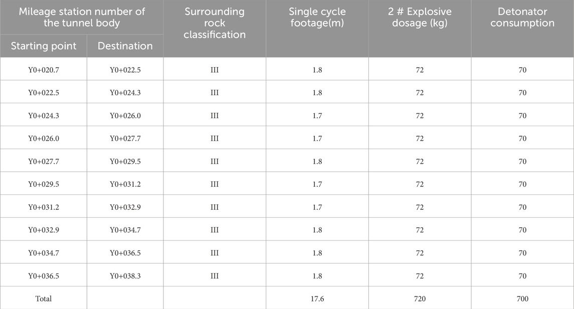
Table 2. Statistical data of the original wedge-shaped excavation blasting site.
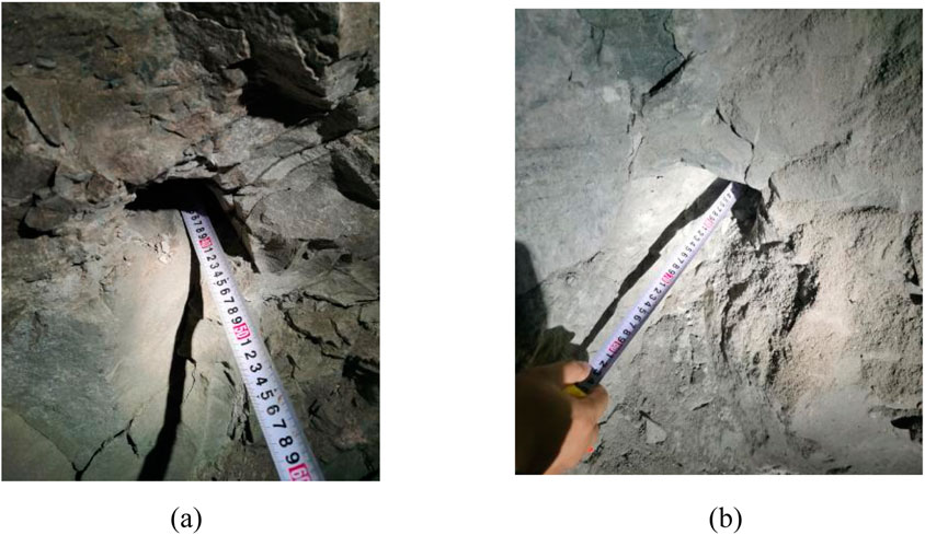
Figure 4. Post-blast hole remnants in the original scheme. (a) 40 cm deep cut hole remnant. (b) 50 cm deep perimeter hole remnant.
4 Blasting (cutting) parameters in the compound scheme
4.1 Drilling parameters
On the basis of the original blasting scheme, short straight holes were added at the diameter position of the central axis of the tunnel face. According to the blasting mechanism of straight holes cut with relief holes, the tensile stress reflected from the post-explosion stress wave on the relief hole wall must be greater than the tensile strength of the rock. That is,
where
where
where
In general, the tensile strength of a rock is 1/20–1/10 of its compressive strength. Based on the physical and mechanical parameters of the tunnel rock mass in Table 1, the tensile strength here can reach 5 MPa. However, blasting is extremely rapid and is a dynamic process with a high strain rate. Therefore, the rock tensile strength
Based on relevant production experience and previous studies, excessively small spacing can cause premature leakage of detonation gases, thereby diminishing the throw effect (Yi et al., 2024). In practice, the burden for straight-hole cuts is typically around 20 cm. To enhance the reliability of short straight-hole cutting, the calculated values were further reduced with reference to proven applications. In the test, the burden between the charge hole and the relief hole was set to 20 cm, with a hole spacing of 15 cm and a vertical distance of 1.5 m from the floor excavation line. Three rows of blastholes were arranged, comprising a total of 15 holes. The central row consisted of charged holes, whereas the relief holes on either side provided both compensation space and a secondary free surface, allowing the rock to move toward the relief holes and the tunnel face. The rock at the bottom of the tunnel experienced the greatest confinement, making post-fragmentation displacement most difficult; thus, the charge holes were overdrilled by 10 cm. To prevent breakthrough between these holes and the inclined cut, the charge hole depth was set at 1.6 m, and the relief hole depth was set at 1.5 m. The blasthole layout for the proposed compound scheme is illustrated in Figure 5.
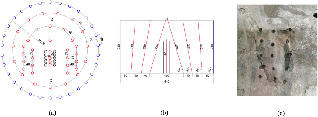
Figure 5. Blasthole layout in the proposed blasting scheme (unit: cm). (a) Layout plan of blastholes. (b) Blasthole profile. (c) On-site drilling of short straight holes.
4.2 Charge and detonation parameters
In the compound test scheme, the charging parameters were increased relative to those of the original wedge-cut blasting design, with a total of 84 kg of explosives per round and an additional 12 kg of half-cartridge explosives, all charged continuously. Five central charge holes were added, and the number of detonators remained at 70. Following the method outlined by Wei-Yi et al. (2024), the explosive distribution was determined according to the type and arrangement of the blastholes. The quantity, charge, and firing sequence of each blasthole type are presented in Table 3. These parameters were verified and adjusted through field trials until an optimal blasting effect was obtained. The initiation system employs digital electronic detonators to precisely control delay timing, with a total of eight delay periods set, each with an interval of 50 ms, which is consistent with the original scheme. After repeated trials and considering the rules governing the allocation of explosives and detonators, satisfactory blasting performance could still be achieved when detonators were issued integer multiples of ten and two perimeter holes that remained uncharged.
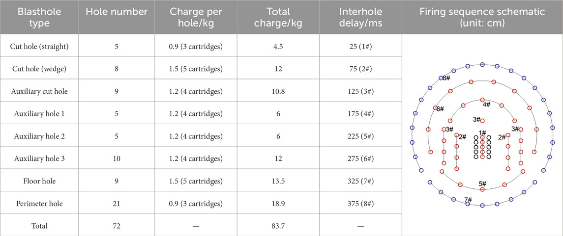
Table 3. Design of the test blasting parameters.
5 Blasting effect analysis for the compound scheme
5.1 Comparison of efficacy
In terms of the number of blastholes, the original wedge-cut design included 67 holes, whereas the proposed short straight-hole + wedge-cut design included 82 holes, representing an increase of 15 holes, or 22.39%. All additional holes were shallow, averaging 1.5 m in depth, adding 22.5 m to the total drilling length. Given that the total blasthole depth in the original scheme was 154 m, this represented a 14.61% increase. Drilling was carried out by six workers operating five YT-28 pneumatic leg drills simultaneously. In the original arrangement, one drilling cycle required 2.5 h, and boring a shallow hole of 1.5–1.6 m typically took 2 min. If a single drill was used, adding 15 shallow holes would extend the drilling time by nearly 20% compared with the original scheme. However, as the equipment operated in parallel, the actual increase in total drilling time was minimal, and the overall number of cycles for drilling, charging, and blasting was largely unaffected, the comparison of work efficiency is shown in Table 4. With respect to pyrotechnic consumption, the modified scheme required 12 kg more explosives. Repeated field trials revealed that effective blasting results could still be achieved when two perimeter holes were left uncharged without altering the total number of detonators, which remained the same as in the original scheme. The blasting performance obtained under the new arrangement is shown in Figure 6.
Table 4. Comparison of work efficiency.
Figure 6. Blasting effect of the proposed test scheme.
5.2 Comparison of the main technical indicators
A series of experiments was carried out on the two cutting methods in a flat tunnel section with Class III surrounding rock, and the primary technical and economic indicators were compared, as summarized in Table 5. In terms of single-round advance, the original wedge-cut method achieved 1.7–1.8 m per round, with a blasthole utilization rate of 73.91%–78.26%. In contrast, the short straight-hole + wedge compound cut scheme reached 2.0–2.1 m per round, with utilization rates ranging from 86.96% to 91.30%. This represents an increase of 0.3 m in advance per round and an improvement in blasthole utilization of more than 10%. With respect to single-round pyrotechnic consumption, the specific charge for both schemes was nearly identical; however, the compound cut method reduced detonator usage by 0.4 detonators/m3 compared with the original design, offering greater economic efficiency. While the compound cut increased the total drilling length by 22.5 m, the cost impact was minimal. Nonetheless, the slightly longer single-round drilling time introduced a marginally greater operational risk for blasting personnel.
Table 5. Comparison of the main technical and economic indicators.
5.3 Comparison of blasting fragmentation rates
From the perspective of the blasting effect, there was a serious phenomenon of remnant holes in the original wedge cut blasting plan, with insufficient cuts in the middle, which affected the throw of auxiliary holes and occasionally resulted in large-sized blocks. The proposed short straight hole + wedge compound cut scheme could break the fragments more evenly, making it easier for the raking machine to remove slag. The compound scheme also had fewer remaining holes on the tunnel surface, making it easier to perform the next round of drilling. Moreover, the dam filling works of the key hub project required transitional materials, so the blasted fragments from the emptying tunnel were screened by removing the small number of oversized blocks exceeding 30 cm in diameter. The gradation curve is shown in Figure 7 below. According to the screening data, the mass percentage of fragments smaller than 200 mm in diameter was 92%, whereas those smaller than 60 mm accounted for 39.3%.The grading curve of explosive slag is between the upper and lower envelope lines of the source material. Based on this analysis, the processed blasting residue could be used as a transitional material for dam filling.
Figure 7. Gradation curve of blasted fragments.
6 Conclusion
Based on drill-and-blast excavation of hard rock tunnels, combined with theoretical analysis and formula derivation, this study employed a short straight-hole + wedge compound cut scheme and conducted blasting tests. The blasting performance of the compound scheme was analyzed and compared with that of the original wedge-cut scheme in terms of blasting efficacy, key technical indicators, and fragmentation. The following conclusions were drawn.
1. In designing blasting parameters for the compound cut scheme in hard rock tunnels, accounting for the high strain rate effect on rock tensile strength ensured the accuracy of calculated parameters such as the distance between charge holes and relief holes.
2. Implementation of the compound cut scheme increased the single-round advance from 1.7 to 1.8 m in the original design to 2.0–2.1 m—an improvement of 0.3 m—and enhanced the blasthole utilization rate from 73.91%–78.26% to 86.96%–91.30%, representing a gain of more than 10%. Although the specific charge remained nearly unchanged, detonator consumption was reduced by about 0.4 detonators/m3, reflecting improved economic efficiency.
3. Adoption of the compound cut scheme resulted in fewer remaining holes and finer fragmentation at the tunnel face, thereby facilitating subsequent mucking and drilling operations. On-site fragment size screening data indicated that, in small tunnels within Class III surrounding rock, the slag produced by this blasting scheme could serve as a transitional material for dam filling.
4. The compound cut scheme involved a slight increase in the number of shallow straight holes. However, given the drilling efficiency, its effect on overall construction efficiency was minimal compared with the original scheme.
Data availability statement
The original contributions presented in the study are included in the article, further inquiries can be directed to the corresponding author.
Author contributions
MT: Writing – original draft, Writing – review and editing. XT: Writing – review and editing. GH: Writing – review and editing. SP: Writing – review and editing. LY: Writing – review and editing. JX: Writing – review and editing.
Funding
The author(s) declare that financial support was received for the research and/or publication of this article. Yunnan Provincial Department of Transport Technology Innovation and Demonstration Project (2025--16), CCCC Key R&D Project (No. 2023--ZJKJ--14).
Conflict of interest
Authors MT and GH were employed by Wenshan Tianwen Expressway Investment and Development Co., Ltd. Author XT was employed by CCCC Rail Transit Branch. Authors SP, LY, and JX were employed by CCCC Second Harbor Engineering Co., Ltd.
The authors declare that this study received funding from CCCC. The funder had the following involvement in the study: participated in the design of blasting parameters and analysis of blasting effects in the experimental plan.
Generative AI statement
The author(s) declare that no Generative AI was used in the creation of this manuscript.
Any alternative text (alt text) provided alongside figures in this article has been generated by Frontiers with the support of artificial intelligence and reasonable efforts have been made to ensure accuracy, including review by the authors wherever possible. If you identify any issues, please contact us.
Publisher’s note
All claims expressed in this article are solely those of the authors and do not necessarily represent those of their affiliated organizations, or those of the publisher, the editors and the reviewers. Any product that may be evaluated in this article, or claim that may be made by its manufacturer, is not guaranteed or endorsed by the publisher.
References
Bao-Long, H. (2014a). Research progress on theory and technology of trenching and blasting in rock roadway excavation. China Min. J. 23 (10), 103–106. doi:10.3969/j.issn.1004-4051.2014.10.024
Bao-Long, H. (2014b). Application of collimated hole grooving technology in large-section tunnel excavation. Blasting Blasting 31 (1), 65–68. doi:10.3963/j.issn.1001-487X.2014.01.014
Gang, H., Hong-Lu, F., and Zhi-Yu, G. (2018). Mechanical mechanism and numerical simulation analysis of large hollow compound cylindrical straight-hole cut. China Saf. Prod. Sci. Technol. 14 (9), 129–135. doi:10.11731/j.issn.1673-193x.2018.09.021
Geglio, M. (1997). Spherical vessel subjected to explosive detonation loading. Int. J. Press. Vessel and Pip. 74 (2), 83–88. doi:10.1016/s0308-0161(97)00024-0
Hai-Bo, W., Qi, Z., and Yao-Cai, Z. (2015). Numerical simulation analysis and application of explosion stress field of vertical cut with large diameter hollow hole in vertical shaft. J. Rock Mech. Eng. 34 (S1), 3223–3229. doi:10.13722/j.cnki.jrme.2014.0296
Ping, W. (2021). Straight cut blasting test and control measures of an underground metal mine. Metal. Mine 8, 52–56. doi:10.19614/j.cnki.jsks.202108009
Qi-Yue, L., Zheng-Yu, W., and Wu-Lin, H. (2018). Improvement and analysis of the calculation model of hole effect in straight cut. J. Min. Saf. Eng. 35 (5), 925–930. doi:10.13545/j.cnki.jmse.2018.05.007
Ren-Shu, Y., Yan-Bing, W., Zhao-Ran, Z., Jin-jing, Z., Chang-Da, Z., and Shu-Xuan, L. (2022). New technology and application of trench excavation and blasting in urban engineering. Chin. Sci. Found. 36 (1), 120–127. doi:10.16262/j.cnki.1000-8217.2022.01.028
Rong-rong, M. (2018). Study on tensile properties and damage and fracture mechanism of coal-bearing sandstone under high strain rate. Xuzhou: China University of Mining and Technology.
Wei-Yi, G., Ying-Kang, Y., and Yu-Xiang, D. (2024). Field test on blasting excavation and over-under-excavation control of long-cut straight hole in medium-section tunnel. Blasting 41 (2), 32–39. doi:10.3963/j.issn.1001-487X.2024.02.005
Xiao-Ming, L., and Shi-Hai, C. (2019). Waveform prediction of surface vibration caused by slotting hole blasting in tunnel excavation. Chin. J. Geotechnical Eng. 41 (9), 1731–1737. doi:10.11779/CJGE201909018
Xin-Han, L. I. (2024). Field test of blasting trenching method in small cross-sectional geological exploration. Henan Sci. Technol. 51 (17), 46–49. doi:10.19968/j.cnki.hnkj.1003-5168.2024.17.010
Xing-Jun, F., Bin, C., Jun, X., and Jin-Xi, D. (2016). Numerical simulation of cavity-forming process by straight cut blasting with intermediate interval charge. Min. Res. Dev. 36 (9), 88–92. doi:10.13827/j.cnki.kyyk.2016.09.021
Yi, L., Yun-Chen, D., Cheng, L., Ya-Qiao, Y., Xin, L., Hang-Li, G., et al. (2024). Influence of blasting excavation of deep karst tunnel on damage and seepage characteristics of surrounding rock mass. Blasting 41 (03), 85–94. doi:10.3963/j.issn.1001-487X.2024.03.011
Ying-Song, L., Hong-Kui, G., and Shun-Chang, W. (1998). Experimental study on dynamic and static mechanical parameters of rock. J. Rock Mech. Eng. 17 (2), 216–222.
Yu-Jie, W. (2018). Blasting engineering. 2nd Edition. Wuhan: Wuhan University of Technology Publishing House.
Yu-Yin, Y. (2013). Experimental study on the influence of cut area on the utilization rate of tunnel excavation. Blasting 30 (2), 100–103. doi:10.3963/j.issn.1001-487X.2013.02.020
Yuan-Li, C., Yu-Hua, F., Li-Yan, G., Qing, W., and Kang-Kang, Z. (2020). Experimental study on trenching and blasting under complex rock conditions. Min. Res. Dev. 40 (6), 23–27. doi:10.13827/j.cnki.kyyk.2020.06.006
Yue-Yang, Y., and Su-Peng, M. O. (2016). Application of large hole spiral cut blasting in tongkeng mine. Min. Technol. 16 (3), 80–82. doi:10.3969/j.issn.1671-2900.2016.03.031
Keywords: water conveyance tunnel, compound cut blasting, blasting parameters, circular tunnel, experiment
Citation: Tu M, Tang X, He G, Peng S, Yang L and Xu J (2025) Experimental study on blasting with a short straight hole + wedge compound cut scheme in hard rock tunnels. Front. Earth Sci. 13:1684101. doi: 10.3389/feart.2025.1684101
Received: 12 August 2025; Accepted: 30 September 2025;
Published: 22 October 2025.
Edited by:
Zhang Cong, Central South University Forestry and Technology, ChinaReviewed by:
Haifeng Liu, Chinese Academy of Sciences (CAS), ChinaErlei Yao, Yangtze River Scientific Research Institute, China
Copyright © 2025 Tu, Tang, He, Peng, Yang and Xu. This is an open-access article distributed under the terms of the Creative Commons Attribution License (CC BY). The use, distribution or reproduction in other forums is permitted, provided the original author(s) and the copyright owner(s) are credited and that the original publication in this journal is cited, in accordance with accepted academic practice. No use, distribution or reproduction is permitted which does not comply with these terms.
*Correspondence: Songlin Peng, eWxzaGFud2FuZzg2QDE2My5jb20=