 Alok Kumar Ray
 Sagar Vashisht
 Dibakar Rakshit
 K. Ravi Kumar
 Hal Gurgenci
- 1Department of Mechanical Engineering, NIT Jamshedpur, Jamshedpur, India
- 2Department of Energy Science and Engineering, Indian Institute of Technology, Delhi, India
- 3School of Mechanical and Mining Engineering, University of Queensland, Brisbane, QLD, Australia
The promising prospects of high-temperature latent heat storage (HT-LHS) systems are accentuated by their advantages, including significant energy storage density, superior energetic efficiency, quasi-isothermal functionality, and seamless integration with renewable energy systems such as 3rd Gen Concentrated Solar Plant and Thermophotovoltaic systems. This study evaluates the thermo-economic performance of a proposed HT-LHS system having silicon as phase change material (PCM). A single thermal cell and a complete LHS system (consisting of several thermal cells) integrated with the supercritical CO2 cycle are considered for the thermal and economic analyses, respectively. Furthermore, the charging performance of an equivalent thermal cell is compared with a specific Li-ion cell. Notably, a single thermal cell’s gravimetric and volumetric energy densities surpass those of the specific Li-ion cell by approximately fourfold. Moreover, the charging time of the equivalent thermal cell, with minimal heat flow, is notably shorter than that of the Li-ion cell with comparable capacity. In terms of the levelized cost of electricity (LCoE), the HT-LHS technology demonstrates a significantly lower price of 9.547 Rs/kWh when storing 200 MWh of energy. Sensitivity analysis of LCoE reveals the opposite effect of loan repayment years (LOY) compared to other economic parameters. LCoE varies by 23.1%,16.43%,14.4%, and 8.06% by changing Return on equity (ROE), interest rate on the loan (IOL), Operation and maintenance cost, and discount rate from −40% to 40%.
1 Introduction
Effective energy storage is critical in addressing the discrepancy between energy supply and demand and enhancing the dispatchability of renewable energy. Energy can be stored in different forms, such as Mechanical, thermal, electrical, electrochemical, etc.(Nadeem et al., 2019; Huang et al., 2015). Electrochemical storage, especially Li-ion battery storage technologies, is currently considered the most popular technology for storing electrical energy. Li-ion battery storage system has benefits of high energy density, long cycle life, low self-discharge rate, and low maintenance requirements. As demand for portable electronics and electric vehicles grows, Li-ion batteries will likely continue to play an essential role in the energy storage market (Goodenough, 2014).
Unlike Li-ion storage technology, thermal energy storage (TES) can store thermal energy in sensible, latent, or chemical forms (Alva et al., 2018). Thermal storage systems operating at high-temperature are becoming increasingly appealing and effective methods to integrate with 3rd Gen concentrated solar plant (CSP) systems to generate combined heat and power effectively and efficiently. Integration of HT-TES systems can effectively reduce the temporal discrepancy between energy supply and demand caused by solar energy intermittency. Thus, maximizing the reliability and dispatchability of solar energy (Ray et al., 2023). Hence, HT-TES systems represent a potential approach to realizing sustainable energy growth and addressing the dynamic energy needs. Among the thermal storage technologies, HT-LHS and TIPV systems can be effectively integrated to produce power through direct conversion of heat (Datas et al., 2018a). Moreover, LHS has higher energy storage density than sensible heat storage (SHS) and higher maturity than thermochemical heat storage (TCHS) (Nazir et al., 2019).
Numerous investigations have concentrated on creating, conceiving, and assessing LHS systems that employ diverse PCM for gathering thermal energy. By selecting an appropriate phase change material and operating temperature, an LHS system can be tailored to suit a specific application (Aftab et al., 2021). LHS technology has been successfully employed for low (0°C–100°C) and medium (100°C–250°C) temperature applications. However, the technology needs to be evolved at higher operating temperatures to harness maximum benefits. Opolot et al. reported the key parameters affecting the performance of the LHS system operating above 500°C (Opolot et al., 2022).
Third Generation CSP systems with central receivers can attain temperatures exceeding 600°C, enabling their integration with high-performing power conversion systems like the supercritical carbon dioxide (sCO2) Brayton cycle. This elevated temperatures compared to traditional Rankine cycles enhance the solar to power conversion efficiency, reducing the levelized cost of electricity (LCoE) (Mohan et al., 2018; Ramos et al., 2022). Suitable PCM is essential for high-temperature latent heat storage (HT-LHS) to maximize advanced power conversion benefits. Additionally, cogeneration of heat and electricity is efficient at temperatures above 900°C (Luft, 1985), and temperatures exceeding 1,000°C can be directly converted to electrical energy using Thermionic photovoltaic (TIPV) converters (Datas, 2016). Thus, coupling HT-LHS stand-alone systems with TIPV devices enables generation of power directly from high-temperature thermal energy.
HT-LHS systems utilizing metallic PCMs can achieve superior energy densities and storage rates compared to systems having inorganic salts and thus at elevated temperatures enhance exergetic and energetic efficiency of the system (Chen, 2015). Kim et al. presented a systematic process for selecting eutectic inorganic salts for use in latent heat thermal energy storage (LHTES) in the temperature range 450°C–500°C (Kim et al., 2024). Metallic silicon (melting point 1,414°C) outperforms traditional inorganic salt high-temperature PCM, boasting higher thermal conductivity (25–50 W/m K) and energy density (Datas et al., 2018b). Ray et al. conducted a numerical analysis to examine the thermohydraulics of silicon melting in a rectangular cavity and compared it with sodium nitrate (NaNO3) (Ray et al., 2021). Zeneli et al. explored how porosity, vessel configuration, working parameters, and Stefan number affect HT-LHS charging rate using silicon (Zeneli et al., 2019). Hosseini et al. conducted a combined experimental and numerical study to understand the role of buoyancy-driven convection during constrained melting of phase change materials (PCMs) inside a shell and tube heat exchanger. They found that increasing inlet heat transfer fluid (water) temperature to 80°C reduced PCM melting by 37% in the shell and tube heat exchanger (Hosseini et al., 2012). The first large-scale HT-LHS prototype, utilizing silicon as PCM, was introduced by Climate Change Technology in Australia in early April 2019 (Technology, 2019).
Energy storage systems can be assessed for their technical and economic viability through techno-economic analysis which combines thermodynamic and economic models to identify the optimal trade-offs between energy efficiency and economic performance, leading to cost savings and improved sustainability (Balli and Caliskan, 2022). Techno-economics is increasingly relevant for transitioning to a low-carbon economy, offering a holistic view of technology costs and benefits to inform policy and industry decisions (Mohammadi et al., 2021). Emrani et al. provided an overview of recent developments in the field of energy storage; combining a comprehensive assessment of the technical and economic characteristics of the various types of energy storage systems (Emrani and Berrada, 2024). Shan et al. proposed a novel layout integrating LHTES with a heat pump and assessed it according to different seasons, LHTES height-to-diameter (H/D) ratios, mass ratios of inflow water to radiator return water, and levelized cost of energy (LCOE) (Shan et al., 2024). Jorgenson et al. found that CSP-TES setups have lower overall costs than PV with batteries, even with the least expensive battery cost estimation (Jorgenson et al., 2016). Liu et al. conducted a techno-economic performance comparison between sensible and latent heat storage for CSP plants, highlighting impact of geometric dimensions and cost hypothesis on techno-economic performance of the TES system and suggesting that low thermal efficiency storage system can be cost-effective (Liu et al., 2021). Musi et al. performed a techno-economic analysis of CSP system using LCoE as economic indicator (Musi et al., 2017). However, more literature on techno-economic analysis for LHS systems is needed, creating a knowledge gap regarding their economic viability and thermodynamic performance. Further techno-economic feasibility research is needed to explore the feasibility of using LHS for various applications.
Thermo-economic analysis of HT-LHS systems can provide valuable information from thermodynamic, economic, and environmental perspectives. Comparing the performance of thermal energy storage with battery energy storage can offer insights of their potential advantages and drawbacks, informing future energy storage decisions, and paving the way for further research. In this context, the objectives of the current study are:
1. Concept of integration of a standalone HT-LHS system having silicon as PCM with a supercritical CO2 cycle for power generation.
2. To elucidate a novel approach for comparing the techno-economic performance of the proposed HT-LHS system with a conventional Li-ion battery energy storage system (BESS) of the same capacity.
3. To estimate the levelized cost of electricity for both storage technologies for a rated power output of 50 MW and an energy capacity of 200 MWh.
4. To perform a sensitivity analysis of LCoE of HT-LHS system
2 Proposed standalone high-temperature LHS system
The HT-LHS system combines two technologies for simultaneous heat and electricity production: a high-temperature latent system with third-gen CSP using a sCO2 cycle for solar-heat-power conversion and integrating a TIPV system with wind or PV power plants for power-heat-power conversion. Figure 1 illustrates the schematic layout of both strategies to generate heat and power.
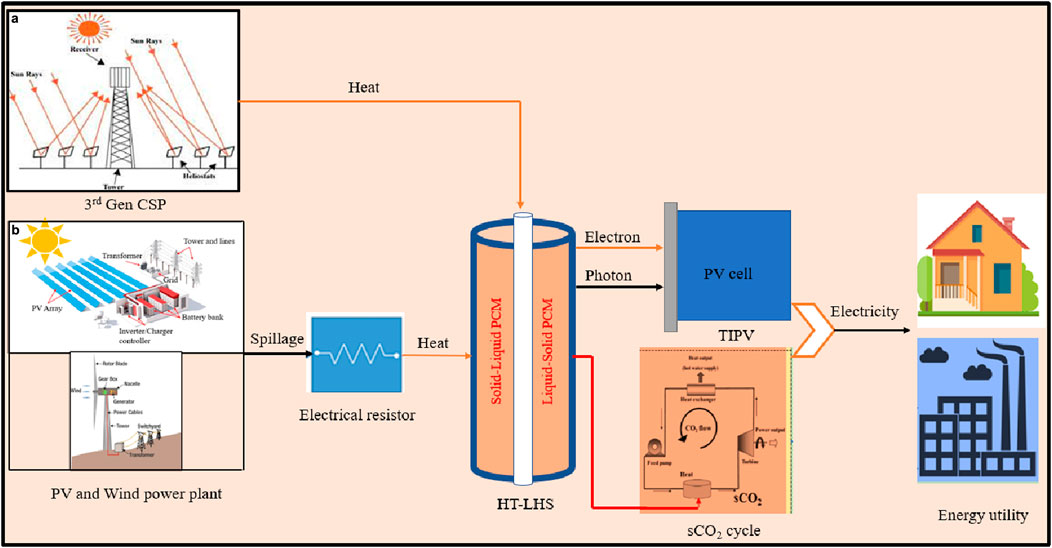
Figure 1. Layout of two proposed strategies of integration for HT-LHS. (a) 3rd Gen CSP + HT-LHS + sCO2 cycle and (b) Spillage from wind and PV plant + HT-LHS + TIPV/sCO2 cycle.
The sCO2 recompression power cycle employs sCO2 as its working fluid, converting thermal energy into mechanical energy for electricity generation. This innovative technology offers advantages over traditional steam cycles, such as higher efficiency, reduced environmental impact, and smaller equipment size. The cycle includes components like a gas turbine, main compressor, recompressors, recuperators, heater, and condenser, with the HT-LHS system serving as the heater. In a standalone setup, the HT-LHS system accumulates thermal energy from renewable sources like solar, photovoltaic, or wind power, storing it in the proposed metallic silicon PCM that has a melting point of 1,414°C. The stored thermal energy is transferred to the sCO2 to raise its turbine inlet temperature, improving cycle efficiency.
Thermionic photovoltaic (TIPV) is a solid-state device that directly converts thermal energy into electricity, merging thermionic and thermophotovoltaic units without intermediate stages. TIPV emits electrons from a cathode to a nearby cold anode in a vacuum within a range of 0.1–100 μm, effectively converting heat into electrical energy. It combines electrons and photons for enhanced power density and heat transfer. It is compatible with different heat sources, including solar concentrators, waste heat, and phase change materials. TIPV is particularly effective with silicon-based HT-LHS technology, which operates above 1,000°C.
3 Methodology
This section compares and discusses the thermodynamic and economic performance of the proposed standalone HT-LHS system with that of the Li-ion battery energy storage system (BESS). Electrical energy spillage from wind and PV power plants can be harnessed and stored as electrical and thermal energy using Li-ion batteries and HT-LHS systems, respectively. From a thermodynamic perspective, electrical energy is considered as high-grade energy and can only be converted to equivalent thermal energy at high temperatures. In this study, the author simulated energy spillage using electrical energy as input to both storage technologies.
The HT-LHS system is illustrated as a thermal battery or cell. A single cell with equal capacity is being evaluated for thermal and Li-ion cell to compare their thermal performance. The thermal cell in this comparison is a single pass, multi tube phase change heat exchanger that utilizes silicon as PCM. In order to perform an economic comparison between thermal and Li-ion battery, a system with high capacity is being evaluated. Henceforth, the HT-LHS system is named as thermal cell or battery in the remaining section of this article. Figure 2a represents a flowchart illustrating electrical energy storage using both technologies. A detailed methodology for techno-economic comparison is shown in Figure 2b.
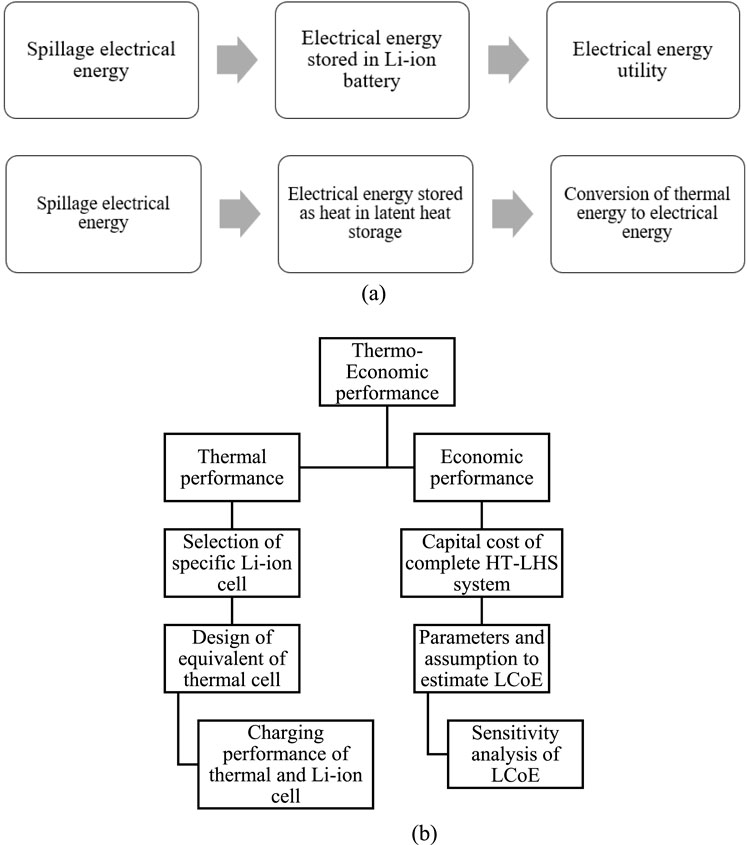
Figure 2. Flow chart of the methodology. (a) Storage of electrical energy using both technologies and (b) Techno-economic performance comparison Schematic of the flowchart for techno-economic performance comparison.
4 Thermal performance comparison
Thermal performance is compared between a Li-ion cell and an equivalent thermal cell. A commercially available cylindrical Li-ion cell (LG 18650HG2) is considered for the analysis and its equivalent thermal cell is designed using thermodynamic principles. The technical specification of the Li-ion cell is mentioned in Table 1. Thermal analysis of Li-ion cell is performed considering the analogy between electrical with thermal circuits as shown in Table 2.

Table 1. Specification of the selected Li-ion cell (LG, 2014).

Table 2. Thermal-electrical circuit analogy.
The storage capacity of the selected Li-ion cell is 10.8 Whe (38.88 kJ) as evaluated from the specification sheet. In order to determine the thermal energy equivalent of the stored electrical energy, the cycle efficiency of the sCO2 cycle is considered and evaluated to be 60.1%. It is estimated that the equivalent thermal energy to be stored in the thermal cell is 64.8 kJ, and the design of the thermal cell utilizes metallic silicon as the high-temperature PCM. The mass and volume of silicon required for thermal cell is estimated utilizing the equation “Storage capacity = mass × latent heat”. According to the calculation, the estimated mass and volume of silicon needed are 0.02 kg and 0.0078 ltr respectively, considering the density of silicon (ρsilicon) = 2,330 kg/m3 and a latent heat of fusion of silicon (hsl,silicon) = 1,800 kJ/kg.
A multi-tube single-pass high-temperature phase change system is proposed to develop the thermal cell. The dimensions of the thermal cell are estimated based on the volume of the cell, with a length of 140 mm, shell diameter of 28 mm, and tube diameter of 12 mm. Similar to the constant current charging of Li-ion cells, the thermal cell is charged by subjecting the outer wall to a uniform heat flux without the flow of sCO2. In contrast, discharging occurs as cold sCO2 flows inside the tube and absorbs energy from the molten PCM. Meanwhile, the 3D model of the lithium-ion cell uses the actual dimensions of the cell, with a diameter of 18 mm and height of 65 mm. For a visual representation of the dimensional parameters of the two systems, refer to Figure 3.
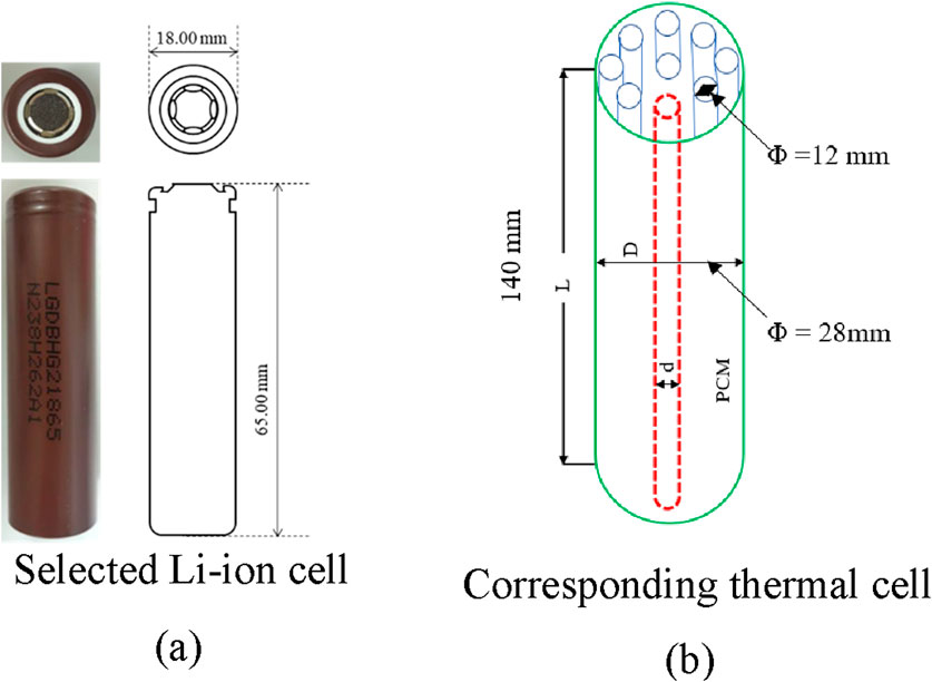
Figure 3. Dimensions of the two selected systems. (a) Li-ion cell, and (b) Thermal cell.
4.1 Numerical formulation
ANSYS Fluent software is utilized to model the charging or melting of silicon in the thermal cell by employing the fixed grid enthalpy-porosity methodology through the Finite volume approach. While charging, the solid-liquid interface is treated as a mushy region that operates as a pseudo-porous zone, exhibiting different levels of porosity between 0 and 1. In this given scenario, when the porosity is 0, it signifies the solid phase, and when it is 1, it indicates the liquid phase. The equations used to conserve energy, mass, and momentum utilized in constructing the model are presented below (Seddegh et al., 2015). The energy equation can be expressed in terms of total enthalpy as Equation 1. Total enthalpy can be expressed in terms of sensible enthalpy and melting fraction in Equation 2. Sensible enthalpy can be expressed as a function of specific heat and reference enthalpy at reference temperature in Equation 3. The energy equation is solved numerically to obtain the temperature distribution in the domain.
Where h is sensible enthalpy, β is liquid/melting fraction, S is energy dissipation, H is total enthalpy, href is sensible enthalpy at Tref and hsl is the latent heat of fusion. The liquid fraction can be defined as in Equation 4. Solving Equation 4 numerically results in the fraction of molten PCM in the complete PCM domain.
Replacing
Where T is instantaneous temperature, Tsol and Tliq are solidus and liquidus temperature of PCM, respectively. The range of values for the parameter β determines the physical state of a region: β = 0 denotes a solid region, β = 1 represents a liquid region, and 0 < β < 1 indicates a mushy zone that contains both solid and liquid phases. The Navier-Stokes equation, which accounts for natural convection, can be written as Equation 6, and porosity function can be expressed as Equation 7. The momentum equation results in velocity distribution in the PCM domain as a function of melting fraction. After PCM begins to melt, there will be velocity of molecules in liquid PCM.
In the context of PCM, function A represents porosity. In contrast, the constant C represents the characteristics of the mushy zone that arises during the temperature interval between the solidus and liquidus points of the material. The morphology of the mushy zone influences the value of C. To prevent division by zero, a small constant (
Except for the buoyancy force that generates natural convection, Boussinesq approximation considers the constant fluid density in all terms of the momentum equation. Reference density (ρref) and reference temperature (Tref) are used to model the body force. As a result, the momentum equation boils down to Equation 8. Density variation can be considered to follow bousinessq approximation as in Equation 9. The Bousinessq approximation considers linear variation of density with temperature.
The continuity equation can be expressed as Equation 10.
The thermal and electrochemical characteristics of Lithium-ion cells are analyzed using Ansys Fluent. The battery model is employed to perform a thermal analysis of a Lithium-ion battery. The rate of heat generation within the battery is determined through a simulation that couples thermal and electrochemical effects. Within the battery cell, the transfer of lithium ions across the anode-separator-cathode sandwich layers is the primary physical process. The Multi-Scale Multi-Domain (MSMD) approach simulates the different physical processes happening in the active zone of the Li-ion battery. This approach involves solving the differential equations governing the thermal and electrical fields of the battery system domain as written from Equations 11–15; (Suresh Patil et al., 2021):
In the given equation,
The source terms,
4.2 Model verification and validation for LHS
Numerical solutions are generally sensitive to the time step and element size of the meshed domain. The model is verified to evaluate the solution’s dependence on the grid size and time step before performing the simulation. Figures 4a,b illustrate the examination of four unique time steps (0.1 s, 0.25 s, 0.5 s, and 1 s) and four various grid sizes (40,000, 62,500, 90,000, and 122,250). The model with 90,000 elements and time steps of 0.25 s and 0.1 s exhibit comparable variations in the liquid fraction. The results show no significant variation with an increase in the number of elements to 122,250. However, the numerical algorithm diverges when a time step of 1 s is used. Therefore, a model with 90,000 elements and a time step of 0.25 s is selected for validating the model.
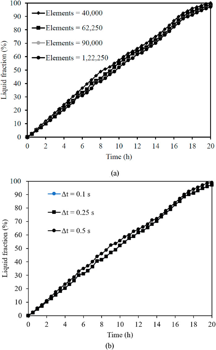
Figure 4. Numerical model verification. (a) Grid independence test, and (b)Time independence test.
The accuracy of enthalpy-porosity (E-P) numerical methodology used in the present study is verified by comparing the results against the numerical and experimental results of Yadav and Sameer for melting of PCM with uniform heat flux as illustrated in Figure 5. The discrepancy between the experimental and numerical results can be attributed to the perfect insulation assumption made in the numerical model. It should be noted that achieving perfect insulation around the PCM domain is challenging in practical experiments, resulting in heat losses that are not accounted for in the numerical model.
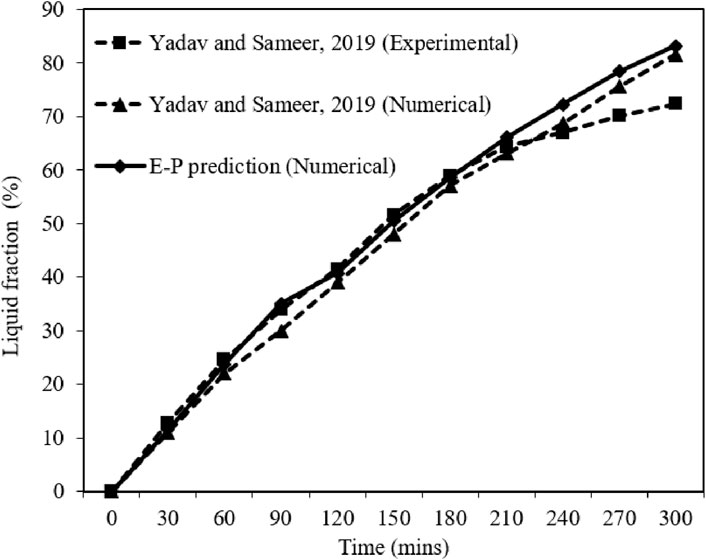
Figure 5. Validation of the current numerical formulation for LHS.
4.3 Thermal performance comparison
The thermal cell is exposed to four uniform heat fluxes at the outer circumference for charging operation. The thermal cell is considered to be fully charged when the liquid fraction of PCM equals to one. Figure 6 illustrates the temporal variation of liquid fraction during the charging of silicon-based thermal cells. It is observed that the charging duration of the thermal cell is linearly proportional to the magnitude of the uniform flux. With an increase in flux from 625 W/m2 to 5,000 W/m2, the charging duration decreases by 89%. Figure 7 represents the temporal variation of the average temperature of PCM (silicon) as a function of input heat flux during charging. With increase in input heat flux from 1250 W/m2 to 5,000 W/m2 (400%), the average temperature of PCM increases by 77.7%.
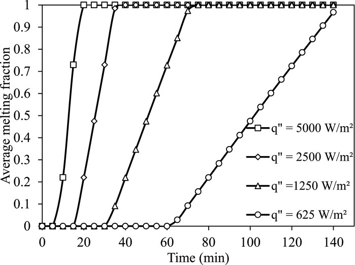
Figure 6. Transient variation of melting fraction of silicon based thermal cell.
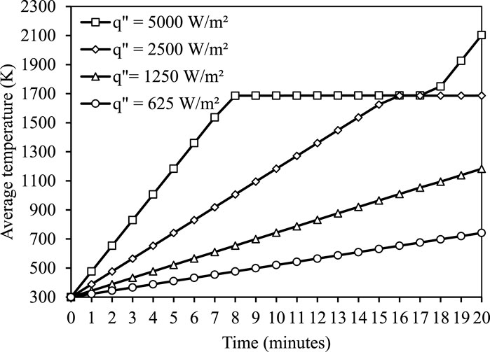
Figure 7. Transient variation of the average temperature of silicon in thermal cell.
The Li-ion battery was charged using a constant current charging method. The battery C-rate measures the current at which the battery is charged or discharged. A battery’s C-rate measures how quickly it can be charged or discharged. A battery’s capacity is often measured in units of 1C, which indicates that a fully charged battery with a rating of 3Ah should be able to supply 3A for 1 h. The charging duration of Li-ion battery decreases linearly with an increase in C rating as shown in Figure 8. The charging time at 0.5C current rating takes 110 min to charge the li-ion battery. For 1C current rating, the charging time was reduced by 48.82%–56.29 min. Similarly, as the C rating increases from 1.0C to 1.5C and 1.5C–2.0C, the charging time reduces by 33.38% and 24.98%, respectively. Overall, with an increase in C rating from 0.5C to 2C, the charging time decreases by 74.43%. Figure 9 shows the temporal variation of charged capacity at different C-rate. The obtained results indicate that a higher C-rating allows a shorter charging time.
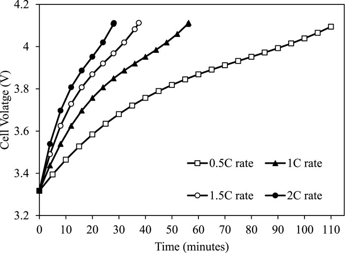
Figure 8. Temporal variation of cell voltage.
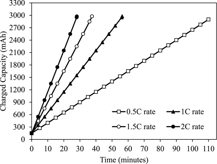
Figure 9. Temporal variation of charged capacity.
Table 3 compares the charging duration and energy density of the thermal cell with Li-ion cell. Both gravimetric and volumetric densities are equally critical to design a compact LHS system. A significantly faster rate of charging is observed for silicon-based thermal cell compared to Li-ion cell except for the lowest heat flow of 7.693 W (q″ = 625 W/m2), the charging duration of thermal cell is 13.5% lower than the charging duration of Li-ion cell.
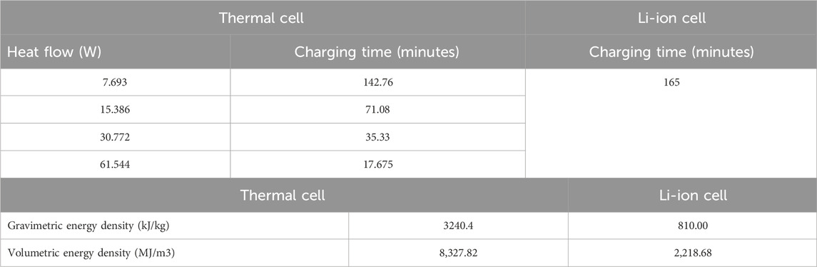
Table 3. Comparison between thermal cell and Li-ion cell.
4.4 Economic performance
The economic performance of the HT-LHS system is estimated in terms of the Levelized cost of electricity (LCoE) as the financial indicator. The following assumptions are considered for the estimation of the economic performance:
1. 50 MW of spilled electrical energy to be stored using HT-LHS
2. 4 h of energy storage duration are considered
3. One discharge cycle per day is considered
4. Cost of spilled electricity is not included in the economic analysis
4.4.1 Levelized cost of electricity
The Levelized cost of electricity (LCoE) refers to the price point at which technology will generate enough revenue to cover costs during its useful lifespan. The final result is a cost per kilowatt-hour that considers all relevant factors and expenses over the project lifetime. LCoE can be viewed as the annualized minimum price at which energy must be sold to break even the project’s cost over its useful life. The LCoE analysis is a technique that helps to estimate the advantages and disadvantages of various energy systems. A lower LCoE indicates suggests that the method used to generate electricity is more economically viable. Equation 16 and Equation 17 are utilized to estimate the LCoE.
Where UCEj = Unit cost of electricity in the jth year, d = discount rate, CRF = Capital recovery factor.
CRF can be expressed as Equation 18.
The total annual cost for the jth year and net annual electricity delivered in jth year depends on the type of Energy Storage system. The LCoE is a function of these two inputs, i.e., the yearly total cost and net annual electricity delivered. For high-temperature thermal battery energy storage system, the estimation for these two inputs (the total annual cost and net annual electricity delivered) is explained in the following section.
For an energy storage system, the total annual cost includes the annual cost of the principal amount of the loan, the annual cost of interest on the loan, annual cost of return on equity, annual costs of the operation and maintenance, and annual costs associated with the renewal of the system. The life cycle cost is the sum of yearly costs associated with the project. The costs associated with a particular type of energy system can be summarized as follows:
I. Capital Cost
II. Annual cost of the principal amount of the loan
III. Annual cost of interest on the loan
IV. Annual cost of return on equity
V. Annual costs of the operation and maintenance of the system
VI. Costs associated with the renewal of the system
VII. Other expenses
The input parameters considered to estimate LCoE are capital cost
4.4.2 LCoE for thermal battery system
As described in preceding Section 2, high-temperature latent heat storage (HT-LHS) system having silicon as PCM is considered as thermal battery in this study. The Capital expenditure for a single tank LHS is the summation of direct and indirect costs. The direct cost includes storage material cost, storage tank cost, HTF cost, and overhead cost. The miscellaneous expenses such as piping, valves, fitting, and electrical costs are considered part of the overhead cost. The overhead cost is considered as 15% of the entire cost associated with the storage tank. The indirect cost covers the sales tax, fabrication, and contingency costs. The indirect cost is considered 30% of the direct cost of the system (Nahar, 2002). The cost contributors that are supposed to evaluate the system cost are listed in Table 4. The total capital cost was computed for a thermal battery integrated sCO2 cycle system with a power rating of 50 MW and an energy capacity rating of 200 MWh, comparable to 4 hours of storage. The capital cost is brought to the present value by considering the time value of money. The estimated capital cost of the integrated thermal battery system is estimated to be Rs 3753.863 million.
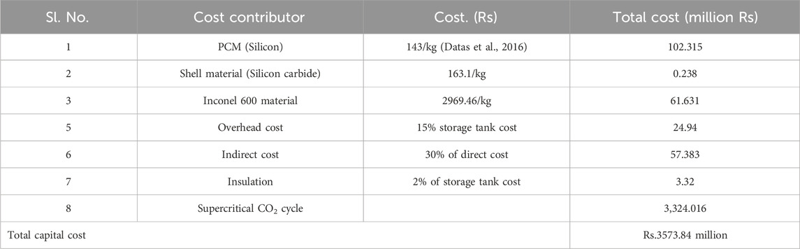
Table 4. Cost contributors of the LHS based thermal battery system.
Cost of operation and maintenance
Discharged Energy
Salvage value: It is defined as the monetary worth of the project after the end of its useful life. In the context of LHS projects, it is the economic value of the controls and instrumentation at the end of their useful life. This control and instrumentation have the potential to be utilized in other services, which will result in a net reduction in investment costs. Zero salvage value is considered for the calculation and can be estimated as Equation 19.
Financial parameters considered to calculate the LCoE of the LHS system integrated with the sCO2 cycle are mentioned in Table 5; (Shri Gireesh, 2016).
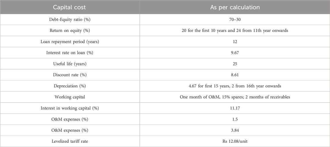
Table 5. Financial parameters for LCoE calculation.
LCoE for HT-LHS system (Thermal battery) integrated with sCO2 cycle with a rated power of 50 MW and an energy capacity of 200 MWh is found to be 9.547 Rs/kWh.
4.5 Sensitivity analysis
A sensitivity analysis is conducted to estimate the degree of reactiveness of LCoE with individual financial parameters. In the present study, the sensitivity of LCoE is represented as a function of discount rate (DR), loan repayment years (LRY), the interest rate on loan (IOL), return on equity (ROE), and operation and maintenance cost (O&M). Figure 10 illustrates the sensitivity of LCoE with the variation of financial parameters from −40% to +40% for thermal and Li-ion batteries, respectively. From the sensitivity plot, LCoE is most sensitive to ROE and least sensitive to DR for thermal battery. IOL is the second most sensitive parameter having a significant effect on LCoE. However, LRY has the opposite effect on LCoE as compared to other financial parameters. Unlike other parameters, LCoE decreases by 9.23% with a variation of LRY from −40% to +40%. For Li-ion battery, ROE and LRY are the most and least sensitive parameters, respectively.
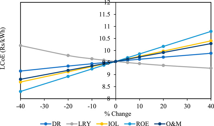
Figure 10. Sensitivity analysis for LCoE of the latent thermal storage system.
5 Conclusion
In conclusion, the thermo-economic study presents compelling evidence regarding the promising potential of a metallic high-temperature latent heat storage (HT-LHS) system integrated with sCO2 recompression cycles for simultaneous heat and power generation.
Firstly, silicon as PCM in HT-LHS systems showcases notable advantages, including significantly shorter charging durations compared to equivalent Li-ion batteries. This reduction in charging time, coupled with the approximately fourfold higher energy density of thermal cells compared to Li-ion cells, underscores the efficacy of HT-LHS technology in energy storage applications. A comprehensive economic analysis of the integrated HT-LHS system and sCO2 recompression cycle reveals a reasonable LCoE of 9.547 Rs/kWh for 200 MWh storage capacity. Sensitivity analysis further highlights the robustness of HT-LHS technology, particularly regarding return on equity (ROE), thus affirming its economic viability. However, further financial analyses of Li-ion battery are warranted to compare the two technologies comprehensively. Thus, our study underscores the importance of thorough assessments and continued research to unlock the full potential of HT-LHS systems in the evolving landscape of energy storage technologies.
Data availability statement
The raw data supporting the conclusions of this article will be made available by the authors, without undue reservation.
Author contributions
AR: Writing – original draft, Writing – review and editing, Conceptualization, Data curation, Formal Analysis, Investigation, Methodology, Validation, Visualization. SV: Conceptualization, Data curation, Formal Analysis, Investigation, Methodology, Validation, Visualization, Writing – original draft, Writing – review and editing. DR: Writing – original draft, Writing – review and editing, Funding acquisition, Project administration, Resources, Software, Supervision. RK: Funding acquisition, Project administration, Resources, Supervision, Writing – original draft, Writing – review and editing. HG: Funding acquisition, Resources, Supervision, Validation, Writing – original draft, Writing – review and editing.
Funding
The author(s) declare that no financial support was received for the research and/or publication of this article.
Acknowledgments
The collaborative research work was made possible with the support of UQIDAR, and the authors express their gratitude towards this organization.
Conflict of interest
The authors declare that the research was conducted in the absence of any commercial or financial relationships that could be construed as a potential conflict of interest.
The author(s) declared that they were an editorial board member of Frontiers, at the time of submission. This had no impact on the peer review process and the final decision.
Generative AI statement
The author(s) declare that no Generative AI was used in the creation of this manuscript.
Publisher’s note
All claims expressed in this article are solely those of the authors and do not necessarily represent those of their affiliated organizations, or those of the publisher, the editors and the reviewers. Any product that may be evaluated in this article, or claim that may be made by its manufacturer, is not guaranteed or endorsed by the publisher.
References
Aftab, W., Usman, A., Shi, J., Yuan, K., Qin, M., and Zou, R. (2021). Phase change material-integrated latent heat storage systems for sustainable energy solutions. Energy Environ. Sci. 14 (8), 4268–4291. doi:10.1039/D1EE00527H
Alva, G., Lin, Y., and Fang, G. (2018). An overview of thermal energy storage systems. Energy 144, 341–378. doi:10.1016/j.energy.2017.12.037
Balli, O., and Caliskan, H. (2022). Various thermoeconomic assessments of a heat and power system with a micro gas turbine engine used for industry. Energy Convers. Manag. 252 (Jan), 114984. doi:10.1016/J.ENCONMAN.2021.114984
Chen, G. (2015). Metallic composites phase-change materials for high-temperature thermal energy storage.
Datas, A. (2016). Hybrid thermionic-photovoltaic converter. Appl. Phys. Lett. 108 (14). doi:10.1063/1.4945712
Datas, A., Cristobal, A. B., Del Cañizo, C., Antolín, E., Beaughon, M., Nikolopoulos, N., et al. (2018a). AMADEUS: next generation materials and solid state devices for ultra high temperature energy storage and conversion. AIP Conf. Proc. 2033 (November), 170004. doi:10.1063/1.5067168
Datas, A., Ramos, A., Martí, A., del Cañizo, C., and Luque, A. (2016). Ultra high temperature latent heat energy storage and thermophotovoltaic energy conversion. Energy 107, 542–549. doi:10.1016/j.energy.2016.04.048
Datas, A., Zeneli, M., Del Cañizo, C., Malgarinos, I., Nikolopoulos, A., Nikolopoulos, N., et al. (2018b). Molten silicon storage of concentrated solar power with integrated thermophotovoltaic energy conversion. AIP Conf. Proc. 2033, 090005. doi:10.1063/1.5067099
Emrani, A., and Berrada, A. (2024). A comprehensive review on techno-economic assessment of hybrid energy storage systems integrated with renewable energy. J. Energy Storage 84 (PB), 111010. doi:10.1016/j.est.2024.111010
Goodenough, J. B. (2014). Electrochemical energy storage in a sustainable modern society. Energy Environ. Sci. 7, 14–18. doi:10.1039/c3ee42613k
Hosseini, M. J., Ranjbar, A. A., Sedighi, K., and Rahimi, M. (2012). A combined experimental and computational study on the melting behavior of a medium temperature phase change storage material inside shell and tube heat exchanger. Int. Commun. Heat. Mass Transf. 39 (9), 1416–1424. doi:10.1016/j.icheatmasstransfer.2012.07.028
Huang, Q., Wang, Z., Zhu, J., Wang, D., and Du, B. (2015). Review on the distributed energy storage technology in the application of the micro network. MATEC Web Conf. 22, 02019. doi:10.1051/matecconf/20152202019
Jorgenson, J., Mehos, M., and Denholm, P. (2016). Comparing the net cost of CSP-TES to PV deployed with battery storage. AIP Conf. Proc. 1734, 080003. doi:10.1063/1.4949183
Kim, H., Seo, J., Hassan, Y. A., Yoo, J. S., Qin, S., and Hartvigsen, J. L. (2024). Evaluation and selection of eutectic salts combined with metal foams for applications in high-temperature latent heat thermal energy storage. J. Energy Storage 76 (August 2023), 109790. doi:10.1016/j.est.2023.109790
Liu, M., Jacob, R., Belusko, M., Riahi, S., and Bruno, F. (2021). Techno-economic analysis on the design of sensible and latent heat thermal energy storage systems for concentrated solar power plants. Renew. Energy 178, 443–455. doi:10.1016/J.RENENE.2021.06.069
Luft, W. (1985). High-temperature solar thermal energy storage. Int. J. Sol. Energy 3 (1), 25–40. doi:10.1080/01425918408914381
Mohammadi, K., McGowan, J. G., and Powell, K. (2021). Thermoeconomic analysis of a multigeneration system using waste heat from a triple power cycle. Appl. Therm. Eng. 190 (February), 116790. doi:10.1016/j.applthermaleng.2021.116790
Mohan, G., Venkataraman, M., Gomez-Vidal, J., and Coventry, J. (2018). Thermo-economic analysis of high-temperature sensible thermal storage with different ternary eutectic alkali and alkaline earth metal chlorides. Sol. Energy 176 (June), 350–357. doi:10.1016/j.solener.2018.10.008
Musi, R., Grange, B., Sgouridis, S., Guedez, R., Armstrong, P., Slocum, A., et al. (2017). Techno-economic analysis of concentrated solar power plants in terms of levelized cost of electricity. AIP Conf. Proc. 1850 (June). doi:10.1063/1.4984552
Nadeem, F., Hussain, S. M. S., Tiwari, P. K., Goswami, A. K., and Ustun, T. S. (2019). Comparative review of energy storage systems, their roles, and impacts on future power systems. IEEE Access 7, 4555–4585. doi:10.1109/ACCESS.2018.2888497
Nahar, N. M. (2002). Capital cost and economic viability of thermosyphonic solar water heaters manufactured from alternate materials in India. Renew. Energy 26 (4), 623–635. doi:10.1016/S0960-1481(01)00150-1
Nazir, H., Batool, M., Bolivar Osorio, F. J., Isaza-Ruiz, M., Xu, X., Vignarooban, K., et al. (2019). Recent developments in phase change materials for energy storage applications: a review. Int. J. Heat. Mass Transf. 129, 491–523. doi:10.1016/j.ijheatmasstransfer.2018.09.126
Opolot, M., Zhao, C., Liu, M., Mancin, S., Bruno, F., and Hooman, K. (2022). A review of high temperature (≥500°C) latent heat thermal energy storage. Renew. Sustain. Energy Rev. 160, 112293. doi:10.1016/j.rser.2022.112293
Ramos, A., López, E., del Cañizo, C., and Datas, A. (2022). Cost-effective ultra-high temperature latent heat thermal energy storage systems. J. Energy Storage 49, 104131. doi:10.1016/j.est.2022.104131
Ray, A. K., Rakshit, D., Ravi Kumar, K., and Gurgenci, H. (2021). Silicon as high-temperature phase change medium for latent heat storage: a thermo-hydraulic study. Sustain. Energy Technol. Assessments 46 (September 2020), 101249. doi:10.1016/j.seta.2021.101249
Ray, A. K., Rakshit, D., Ravi Kumar, K., and Gurgenci, H. (2023). Strength-Weakness-Opportunities-Threats-Unusual (SWOT-U) behavior analysis of silicon as phase change material for high-temperature latent heat storage. Therm. Sci. Eng. Prog. 38 (Feb), 101627. doi:10.1016/J.TSEP.2022.101627
Seddegh, S., Wang, X., and Henderson, A. D. (2015). Numerical investigation of heat transfer mechanism in a vertical shell and tube latent heat energy storage system. Appl. Energy 154, 698–706. doi:10.1016/j.applthermaleng.2015.05.067
Shan, L., Martin, A., and Chiu, J. N. W. (2024). Techno-economic analysis of latent heat thermal energy storage integrated heat pump for indoor heating. Energy 298 (March), 131291. doi:10.1016/j.energy.2024.131291
Shri Gireesh, B. (2016). Pradhan. Central Electricity Regulatory Commission. Available online at: http://cercind.gov.in/2016/orders/sm_3.pdf.
Suresh Patil, M., Seo, J. H., and Lee, M. Y. (2021). A novel dielectric fluid immersion cooling technology for Li-ion battery thermal management. Energy Convers. Manag. 229 (December 2020), 113715. doi:10.1016/j.enconman.2020.113715
Zeneli, M., Malgarinos, I., Nikolopoulos, A., Nikolopoulos, N., Grammelis, P., Karellas, S., et al. (2019). Numerical simulation of a silicon-based latent heat thermal energy storage system operating at ultra-high temperatures. Appl. Energy 242 (March 2018), 837–853. doi:10.1016/j.apenergy.2019.03.147
Nomenclature
BESS Battery energy storage system
CCT Climate change technology
CRF Capital recovery factor
CSP Concentrated solar plant
DOD Depth of discharge
DR Discount rate
HT High-temperature
IOL Interest rate on loan
LCoE Levelized cost of electricity
LHS Latent heat storage
LRY Loan repayment year
MSMD Multi scale multi domain
NTGK Newmann Tiedemann Gu and Kim
TCHS Thermochemical heat storage
TES Thermal energy storage
O&M Operation and maintenance
PCM Phase change material
PV Photovoltaic
PVC Present value cost
ROE Return on equity
SD Self discharge
SHS Sensible heat storage
TIPV Thermionic photovoltaic
UCE Unit cost of electricity
Symbols
C Charging rate
Co Capital cost
Cj Operation and maintenance cost
cp Specific heat at constant pressure
d Discount rate
hsl Latent heat of fusion
jECH Volumetric current transfer rate
qECH Electrochemical reaction heat
s Salvage value
sCO2 Supercritical CO2
Greek Symbols
β Melting fraction
ϵ Small constant
ρ (kg/m3) Density
μ (Pa.s) Dynamic viscosity
Φ (V) Phase potential
σ (S/m) Electric conductivity
Keywords: high-temperature, latent heat storage, Li-ion battery, thermo-economic, LCOE
Citation: Ray AK, Vashisht S, Rakshit D, Ravi Kumar K and Gurgenci H (2025) Thermo-economic assessment of metallic high-temperature latent heat storage system. Front. Therm. Eng. 5:1549926. doi: 10.3389/fther.2025.1549926
Received: 22 December 2024; Accepted: 08 April 2025;
Published: 24 April 2025.
Edited by:
Bidyut Baran Saha, Kyushu University, JapanReviewed by:
Hakeem Niyas, Rajiv Gandhi Institute of Petroleum Technology, IndiaAbhishek Kumar Singh, University of Twente, Netherlands
Copyright © 2025 Ray, Vashisht, Rakshit, Ravi Kumar and Gurgenci. This is an open-access article distributed under the terms of the Creative Commons Attribution License (CC BY). The use, distribution or reproduction in other forums is permitted, provided the original author(s) and the copyright owner(s) are credited and that the original publication in this journal is cited, in accordance with accepted academic practice. No use, distribution or reproduction is permitted which does not comply with these terms.
*Correspondence: Dibakar Rakshit, ZGliYWthckBkZXNlLmlpdGQuYWMuaW4=