 Huan Huang
 Chongfu Zhang
 Wei Zheng1
 Yong Chen
 Zichuan Yi
 Feng Chi
- 1School of Information and Communication Engineering, Zhongshan Institute, University of Electronic Science and Technology of China, Chengdu, China
- 2School of Electronic Information, University of Electronic Science and Technology of China, Zhongshan Institute, Zhongshan, China
- 3Southwest Institute of Electronic Technology (SIET), Chengdu, China
Due to the limitation of analog-to-digital/digital-to-analog converters, photonics-assisted channelized receivers are thought to be a promising approach to receiving wideband microwave signals. Herein, based on the spectrum analysis and the coherent channelization, we develop a photonics-assisted channelized receiver for multi-band microwave signals. In the proposed channelized receiver, the instantaneous spectral analysis is introduced to determine the frequencies and bandwidth of a dynamic wideband signal. The dynamic wideband signal is then received by a multi-band coherent channelizer. By exploiting transparency of the optoelectronic devices, we equivalently build a multi-band coherent channelizer that can work for dynamic microwave signals, where a few optoelectronic devices are required. Compared with the existing coherent channelizers, the operative bandwidth of the proposed multi-band coherent channelizer is much larger (up to 28 GHz). The proposed photonics-assisted channelized receiver doesn’t need tunable optical comb generators and radio frequency sources, and it also doesn’t require knowing the spectrum information in advance. Moreover, the designed example of the proposed photonics-assisted channelized receiver for a 4 GHz original signal in 2–30 GHz microwave bands is given and discussed. The spectrum information of the dynamic original signals is obtained by monitoring the optical power in each sub-channel. We verify the feasibility of the multi-band coherent channelizer by channelizing two 4 GHz linearly-chirped signals with center frequencies of 4 and 28 GHz into four 1 GHz sub-channels, respectively.
Introduction
Microwave signal receivers with larger bandwidth and higher frequency are a pressing need in both commercial and defense applications such as modern radars, communication satellites, radio over fiber systems, and the 5th generation mobile network [1–5]. However, wideband signal receivers are limited to analog-to-digital/digital-to-analog converters [6]. To handle the wideband signal reception with this limitation, channelized receivers that are a specialized class of pre-processors have attracted much attention. A channelized receiver is employed to channelize a wideband signal into N narrowband slices and then these narrowband slices are processed in parallel [7–11], where the processing band of each narrowband is reduced to 1/N. Generally, the operative bandwidth of an electric channelized receiver is limited to a few GHz, because the “Electronic Bottleneck” resists in it [12, 13]. In a photonics-assisted channelized receiver, the operative bandwidth can reach several GHz (tens of GHz) [14–18]. Moreover, photonics-assisted channelized receivers have other advantages such as high compactness, low loss, and immunity to electromagnetic interference [19, 20].
The existing works about photonics-assisted channelized receivers can be classified into three typical categories. In the first channelization category, a radio frequency (RF) signal is first modulated on an optical carrier (OC), and a series of optical filters with consecutive passbands are then introduced to slice the modulated optical signal [10]. The optical filters such as integrated Bragg grating Fabry–Perot devices [10], diffraction gratings [21], and acousto-optic crystals [22] are available. This channelization scheme requires narrowband, flat-top, steep-edge, and precisely centered filter banks to ensure effective separation of slices, hence it suffers from limitations in spectral slice resolution and the available number of channels [19, 23]. Therefore, the second channelization category has been proposed, where multicast copies were generated by modulating the original RF signal on a series of OCs. Then an optical comb filter such as a Fabry-Perot filter (FPF) with a special free spectrum range (FSR) was employed to separate different slices from multicast copies [7–9, 17, 24]. This photonic channelizer is also limited to the comb filter, so the comb filter is desired to have narrowband, flat-top, and steep-edge transmission peaks (TPs). In practice, optical filters with ideal TPs are difficult to achieve. Therefore, application scenarios for these two channelization categories are mostly the instantaneous spectral analysis [7, 25].
Recent approaches to photonics-assisted coherent channelization without optical filters have also been demonstrated [11, 23, 26–30]. This channelization scheme, i.e., the third photonic channelization category demands no optical filters, but it requires a couple of coherent comb light sources with detuning comb line spacing [23, 30]. Specifically, one coherent comb light source provides comb lines for generating optical multicast copies, and the other is employed to generate local oscillators (LOs). It is worth mentioning that the LOs in the third photonic channelization category can be replaced by dual-polarization LOs [31, 32], where the required optical comb lines (OCLs) are reduced. Moreover, other photonics-assisted channelized receivers have also been reported, for instance, the approach relying on wavelength scanning structures [33]. The third-category photonic channelization requires no optical filters, so it can reach the maximum suppression ratio of spurs in each sub-channel. For different scenarios, microwave signals are required to have different bands such as the S-band, C band, and K band [34–37]. Therefore, a microwave signal receiver working at many microwave bands is demanded. However, in existing works about the third photonic channelization category, the operative bandwidth is generally several GHz, and it is difficult to achieve tens of GHz operative bandwidth. Moreover, most of the existing coherent channelized receivers are designed for fixed microwave bands, where the spectrum information should be known in advance. Although the work in [11] has presented a reconfigurable coherent channelized receiver, tunable RF sources are required.
In this work, a photonics-assisted channelized receiver based on the spectrum analysis and the coherent channelization is proposed for multi-band microwave signals. The implementation of this photonics-assisted channelized receiver is twofold including the instantaneous spectral analysis and the coherent channelization. First, the instantaneous spectral analysis is employed to obtain the spectrum information. In the instantaneous spectral analysis, an efficient second-category photonic channelizer is built to obtain the spectrum information because of the large operative bandwidth and low-complexity of the second-category photonic channelizer. Second, a multi-band coherent channelizer belonging to the third-category photonic channelization is designed for a virtual signal covering the entire frequency range. Based on the transparency of photonic devices, we equivalently build a multi-band coherent channelizer that can work for dynamic microwave signals by using a few devices. After determining the spectrum information of the original dynamic signal, this wideband signal with dynamic microwave bands is received by the multi-band coherent channelizer.
Principles
Photonics-Assisted Channelized Receiver for Multi-Band Microwave Signals
Figure 1 schematically depicts the proposed photonics-assisted channelized receiver for multi-band microwave signals. The implementation of this channelized receiver is twofold including the instantaneous spectral analysis and the coherent channelization. First, the instantaneous spectral analysis is performed for an original wideband signal to determine its frequencies and bandwidth, i.e., the spectrum information, as shown in the upper part of Figure 1. Second, introducing two ultra-flat optical comb generators (U-FOCGs), the original signals are received by the multi-band coherent channelizer, which is illustrated in the lower part of Figure 1. By introducing a controller to control the selected OCLs, we equivalently build a coherent channelized receiver by a few devices for multi-band microwave signals.
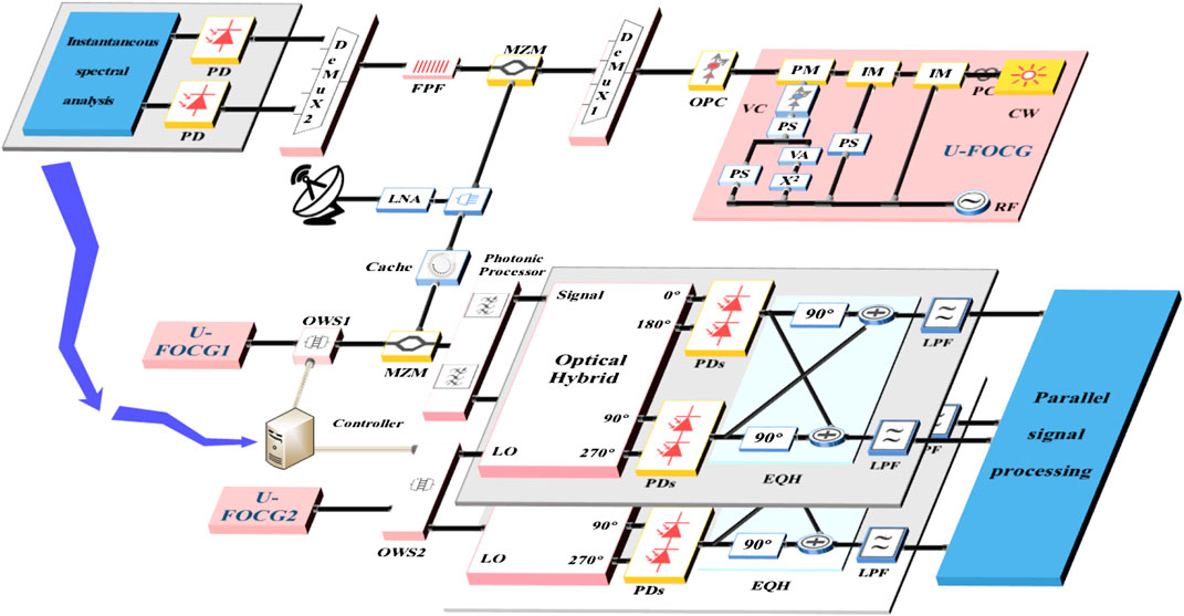
FIGURE 1. Schematic diagram of the proposed photonics-assisted channelized receiver based on the spectrum analysis and the coherent channelization for multi-band microwave signals. U-FOCG, ultra-flat optical comb generator; OPC, optical power control module; DeMux, demultiplexer; MZM, Mach-Zehnder modulator; FPF, Fabry-Perot filter; LNA, low noise amplifier; PD, photodetector; OWS, optical wavelength selection; EQH, electrical quadrature hybrid; LPF, low-pass filter.
In the instantaneous spectral analysis, an efficient photonic channelizer belonging to the second category is designed to analyze the spectrum information of the original dynamic signal.
Firstly, an U-FOCG is implemented to provide OCLs, where two intensity modulators (IMs) and one phase modulator (PM) are cascaded in turn. A demultiplexer called DeMux 1 is then employed to select a series of OCLs from the output of U-FOCG, where adjacent OCLs have the wavelength spacing of δc. The center frequencies (CFs) of the selected OCLs are termed as f1c, f2c … and fnc, where n is equal to [(fH − fL)/2Δδ], the original dynamic signal has frequencies between fL and fH, [(fH − fL)/2Δδ] represents that rounds (fH − fL)/2Δδ to the nearest integer, and Δδ is defined as the detuning parameter. The spectra of the selected OCLs are depicted in Figure 2A.
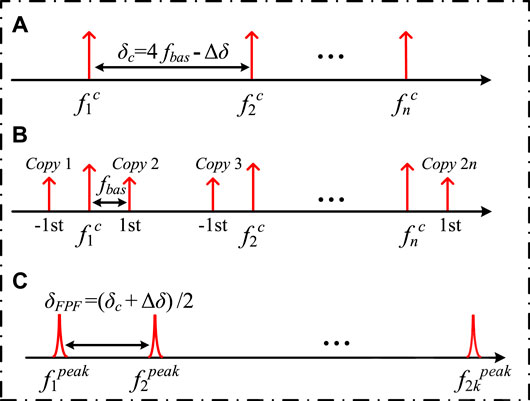
FIGURE 2. Spectra diagrams of (A) the selected optical comb lines, (B) modulated optical comb lines after double sideband modulation, and (C) transmission peaks of the Fabry-Perot filter.
The wavelength spacing δc is determined by the driven RF source in the U-FOCG. Besides, we assume that the original dynamic signal has frequencies between fL and fH. Generally, the bandwidth B of the original signal is much less than the frequency range (fH − fL). By setting the driven RF source, the OCLs selected from the U-FOCG satisfy the following spectral relationship [11, 30],
where
Secondly, the optical powers of the selected OCLs are adjusted by an optical power control module, and these OCLs are then injected into a Mach-Zehnder modulator. After double sideband (DSB) modulation, 2n multicast copies are generated and located on the ±1st sidebands of each OCL, as shown in Figure 2B. Observe that the original signal is amplified by a low noise amplifier [38, 39] before DSB modulation.
Thirdly, a FPF is taken as a comb filter whose FSR δFPF is equal to
The FPF with 2n TPs is introduced to channelize the original signal into a series of narrowband sub-channels, which is termed as Sub-ch1, Sub-ch2 … Sub-ch2n. Specifically, the relationship between the CFs of the first TP and the first OCL satisfies the following equation,
Moreover, the relationship between the full width half maximum pass-band width δ3dB and the δFPF has the following form,
where t is the power transmission coefficient of the mirrors in the FPF.
Finally, these 2n slices are separated by a demultiplexer termed as DeMux 2, where the channels of DeMux 2 match the FPF’s TPs. These slices can be detected by photodetectors (PDs) in parallel, and the frequency range and bandwidth are then determined according to the optical power in each sub-channel. Only a few sub-channels have significant optical power after detecting by PDs because the bandwidth B is much less than the frequency range (fH − fL). The spectrum information will be employed to control the next coherent channelization.
In the coherent channelization, we equivalently build the multi-band coherent channelizer that can work for microwave signals with a large frequency range (fL ≤ f ≤ fH). We assume that a virtual multi-band microwave signal with frequencies from fL to fH is channelized and then received, where the bandwidth and CF of the virtual microwave signal are equal to (fH–fL) and
Firstly, we prepare m
where f1oc represent the CF of the first OC, 1 ≤ r ≤ m, and δs represents the bandwidth of each sub-signal after channelization.
Secondly, the virtual wideband signal is modulated on those OCs to generate multicast copies, and the virtual wideband signal is saved in a cache before modulation. Assuming those m OCs are all modulated, 2m optical multicast copies of the virtual wideband signal termed as v-copies are obtained after DSB modulation, as illustrated in Figure3A.
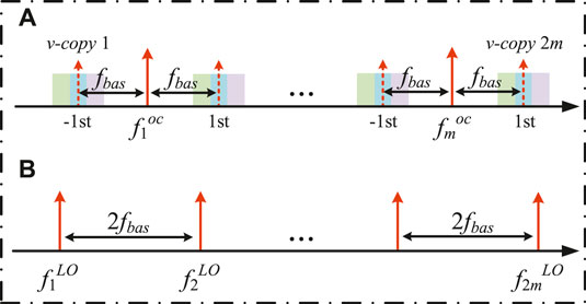
FIGURE 3. Spectra diagrams of (A) the modulated optical carriers s after double sideband modulation and (B) local oscillators generated from ultra-flat optical comb generator 2.
Thirdly, 2m LOs are introduced for coherent detection which can be selected from other U-FOCG (U-FOCG 2), as shown in Figure 3B. These 2m LOs have a fixed wavelength spacing of 2fbas. Besides, the CFs of the first LO and the OC have the following relationship that is
Next, the photonic processor such as the tunable optical filter (TOF) whose channels match those 2m v-copies is introduced to separate them, and an OWS 2 is then employed to separate those 2m LOs, as shown in Figure 1. When the existing works about the third-category photonic channelization are built for directly channelizing the virtual wideband signal, there are 2m optical hybrids (OHs) [40], 8m PDs or 4m balance photodetectors (BPDs), 2m electrical quadrature hybrids (EQHs), and 4m electrical low-pass filters (LPFs) at least. Therefore, the coherent channelized receiver will be very complex and redundant, where huge photonic and electrical deceives are wasted. By exploiting the reconfigurability proposed in [11], although 2k OHs, 8k PDs or 4k BPDs, 2k EQHs, and 4k LPFs
In this work, we designed a multi-band coherent channelizer which only requires 2k OHs, 4k PDs, 2k EQHs, and 4k electrical LPFs, and the CFs of RF sources are fixed. Moreover, for an original signal with dynamic frequencies between fL and fH, its bandwidth and microwave bands are given via the instantaneous spectral analysis. So, the spectrum information is not required knowing in advance.
Assuming 2m separated v-copies and LOs have been generated. Every v-copy consists of different components termed as C1, C2 … CN, where
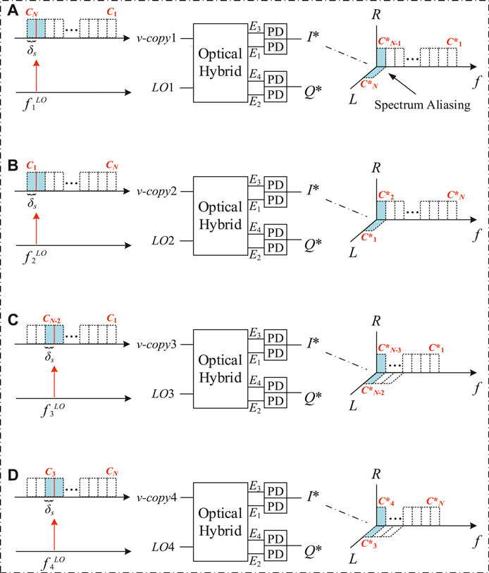
FIGURE 4. Schematic diagrams of 2 × 4 90° optical hybrid reception for the first four v-copies and local oscillators (LOs), where (A–D) show the spectra of the v-copy1 and the LO 1, the v-copy2 and the LO 2, the v-copy3 and the LO 3, as well as the v-copy4 and the LO 4, and the spectra of them after detecting by photodetectors (PDs), respectively.
To address the spectrum aliasing problem, symmetric EQHs displayed in Figure 1 are employed. According to the scattering matrix of the EQH [41], the two output signals of the first EQH have the following form,
In Eq. (7), the I* and Q* signals are generated after processing by the OH and PDs which have the following form,
where
Two tunable LPFs with a bandwidth of δs are introduced to select the corresponding components from those I and Q signals respectively. Namely, two components CN* and C(N − 1)* can be obtained from the v-copy 1. Similarly, other components can also be selected from other v-copies. Finally, parallel signal processing is performed for those narrowband components, where the electrical processers only require a processing band of δs.
The optoelectronic devices such as the OHs, PDs, EQHs, and LPFs in Figure 4 are transparent for the input. The output components after LPFs are only determined by different v-copies and LOs. Then we can only work effective sub-channels and stop those sub-channels that are corresponding to the null components of the virtual multi-band microwave signal. For example, the virtual multi-band microwave signal only contains components C1, C2, CN − 1, and CN, we can channelize and receive this microwave signal by employing v-copy 1, v-copy 2, LO 1, and LO 2. When the virtual multi-band microwave signal contains components CN − 3, CN − 2, CN − 1, and CN at other times, it can be channelized and received by using v-copy 2, v-copy 3, LO 2, and LO 3. However, the OHs, PDs, EQHs, and LPFs used in the coherent channelization are the same for these two different virtual multi-band microwave signals, because these optoelectronic devices are transparent for the input.
As shown in Figure 1, a controller connected to OWS 1 and OWS 2 is introduced to select the necessary OCs (corresponding to specific v-copies) and LOs by the spectrum information from the instantaneous spectral analysis. Therefore, many photonic and electronic devices can be saved. For simplicity, we assume that the
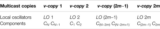
TABLE 1. Relationship among multicast copies, local oscillators, and components.
In other words, we equivalently build a coherent channelized receiver for multi-band microwave signals (between fL and fH) by using T*k devices rather than T*m devices (k << m), where T is a positive integer. Compared with the work in [11], the RF sources do not require tuning, and there is no need to know the spectrum information in advance.
Photonics-Assisted Multi-Band Receiver for Dynamic Signals in 2–30 GHz Bands
Most of the initial coherent channelized receivers [23, 26–32] were designed for fixed microwave bands, where the spectrum information must be known in advance. Those coherent channelized receivers can only work for specific microwave bands. When those coherent channelized receivers are deployed for receiving dynamic 4 GHz signals with frequencies between 2 and 30 GHz, they must have an operative bandwidth of 28 GHz regardless of the actual bandwidth. Therefore, lots of active processing devices are wasted. Moreover, the work in [11] has presented a reconfigurable coherent channelized receiver. Although only 4 GHz operative bandwidth is required based on this scheme, the RF sources employed must be tunable.
Based on the proposed scheme, the instantaneous spectral analysis for the dynamic 4 GHz signals has been finished by the following steps. Setting the detuning parameter Δδ to be 1 GHz, 28 sub-channels are required to monitor the dynamic 4 GHz signal. Firstly, 14 OCLs with a wavelength spacing of 63 GHz were generated, where f1c = 192.722 THz and fbas = 16 GHz.
These OCLs can be generated from the U-FOCG, and the structure of the U-FOCG is illustrated in Figure 5A. First, two IMs and one PM were cascaded in turn, where a continuous-wave laser was connected to the IM1 after a polarization controller. Second, an RF signal source with a frequency of δc/2 is separated into three branches. The 1st branch was used to directly drive the IM1. The 2nd branch was employed to drive the IM2 after the first phase shifter (PS1). The 3rd branch was served to drive the PM, where an electric PS (PS2), a × 2 frequency multiplier, and a variable attenuator were employed to eliminate the 1st undesirable term. Third, after processing by the PS3, a voltage control module including a tunable amplifier and attenuator was used to adjust the voltage of the PM’s driven signal.
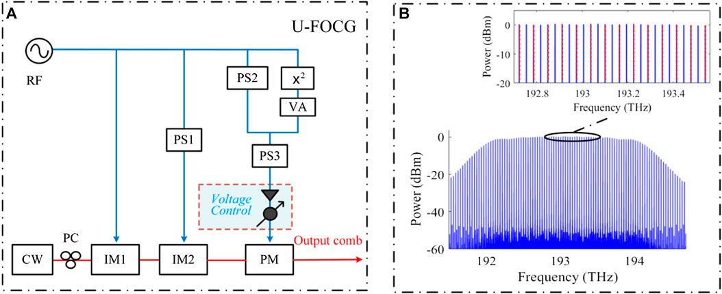
FIGURE 5. (A) Schematic diagram of the ultra-flat optical comb generator (U-FOCG), (B) Spectra of the output of the U-FOCG with 4-dB gain, and the employed 14 optical comb lines with about 0 dBm optical powers. CW, continuous-wave laser; PC, polarization controller; IM, intensity modulator; PS, phase shifter; PM, phase modulator; x2, x2 frequency multiplier; VA, variable attenuator.
A configuration system used for verifying the feasibility of the U-FOCG was established by VPItransmissionMaker. In the verification system, an RF signal source with a CF of 31.5 GHz and an amplitude of 5 V was employed to drive the modulators, and the CF of the continuous-wave laser was equal to 193.1 THz. Moreover, the phase-shift value of the PS1 was set to π/4. In order to fully eliminate the 1st undesirable term, the variable attenuator and the PS2 were set to (1/16)2 and π, respectively. After setting the PS3 to π/9, the driven signal of PM was amplified by the voltage control module and then about 4-dB gain has been available for the driven signal. Finally, the output comb is illustrated in Figure 5B, where the employed 14 OCLs with about 0 dBm optical powers are also illustrated in the inset in Figure 5B.
Secondly, the dynamic 4 GHz signal was modulated on these OCLs. After DSB modulation, 28 optical multicast copies located on the ±1st sidebands of these OCLs were generated. Thirdly, an FPF with an FSR of 32 GHz was introduced to channelize the original signal into 28 narrowband sub-channels, where the CF of the first TP f1peak must satisfy (3). Finally, by monitoring the optical power in every sub-channel, the spectrum information of the dynamic original signal is then determined. For example, when the optical powers in Sub-ch.1 and Sub-ch.2 are significant, the original signal contains frequency bands of 2–3 GHz and 29–30 GHz. Moreover, the relationship among CFs of these OCLs, CFs of these TPs, sub-channels, as well as the monitoring frequency-band range is shown in Table 2.
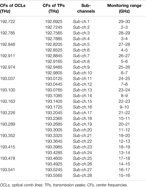
TABLE 2. Relationship among OCLs, TPs, sub-channels, and monitoring bands for dynamics 4 GHz signal.
After obtaining the spectrum information, the 4 GHz dynamic signal was received by the proposed multi-band coherent channelizer. Firstly, U-FOCG 1 in Figure 1 was used to provide 7 OCs, where the RF signal source had a frequency of 31 GHz. The CF of every generated OC satisfies (5), where f1oc = 192.914 THz and δs = 1 GHz. Secondly, 14 v-copies were generated after DSB modulation. Thirdly, 14 LOs with wavelength spacing of 32 GHz were generated from U-FOCG 2, where f1LO = 192.885 THz. It is worth mentioning that CWs used in U‐FOCG 1 and U‐FOCG 2 should be generated from the same optical laser source [23, 27–31]. For the dynamic 4 GHz signal with microwave bands between 2 GHz and 30 GHz, the relationship among CFs of the OCs, v-copies, CFs of the LOs, and the channelized sub-signals is clearly shown in Table 3. Finally, by selecting the corresponding v-copies and LOs according to the spectrum information, the 4 GHz dynamic signal was channelized into four 1 GHz sub-signals and then received.
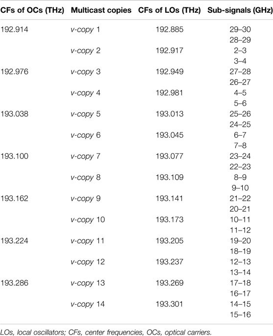
TABLE 3. Relationship among v-copies, LOs, channelized components for dynamics 4 GHz signal.
Results and Discussion
To verify the feasibility of the proposed photonics-assisted multi-band microwave receiver, a proof-of-concept system based on the statements in “Photonics-Assisted Multi-Band Receiver for Dynamic Signals in 2–30 GHz Bands” section has been implemented by OptiSystem and VPItransmissionMaker. First, we performed the instantaneous spectral analysis for 4 GHz dynamic signals. Second, we received the 4 GHz dynamic signals by coherent channelization.
In the instantaneous spectral analysis for the 4 GHz dynamic signals, we considered the following seven cases, as shown in Table 4. We employed four-tone signals to equivalently replace the 4 GHz original signals. For case 1, the four-tone signal with frequencies of 2.5, 3.5, 4.5, and 5.5 GHz was employed. After the second-category photonic channelization, the optical powers received from all sub-channels were illustrated in Figure 6. We can see that the optical powers in Sub-ch.2, Sub-ch.4, Sub-ch.6, and Sub-ch.8 are significantly greater than others.
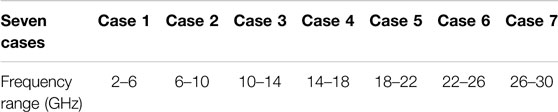
TABLE 4. Considering seven cases and their corresponding frequency ranges.
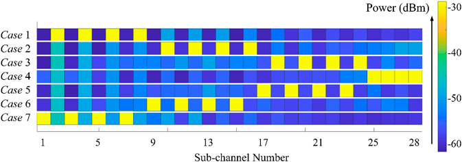
FIGURE 6. Received optical powers in all 28 sub-channels for seven cases with different frequency ranges, where the spectrum information for each case is obtained by monitoring the optical power in all sub-channels.
Namely, we can find the sub-channels with significant optical powers and then determine the spectrum information according to the received optical powers and Table 2. For all seven cases, the received optical powers after the effective second-category photonic channelizer were shown in Figure 6. In practical application, by monitoring the optical power in each sub-channel, the spectrum information is obtained. Based on the spectrum information, different OCs and LOs are selected to implement channelized reception of the original dynamic signal.
For simplicity but without loss of generality, we employed 4 GHz linearly-chirped signals with CFs of 4 and 28 GHz to represent the 4 GHz dynamic signals, as shown in Figure 7. After determining the spectrum information of the linearly-chirped signals, the two linearly-chirped signals were received by the coherent channelization.
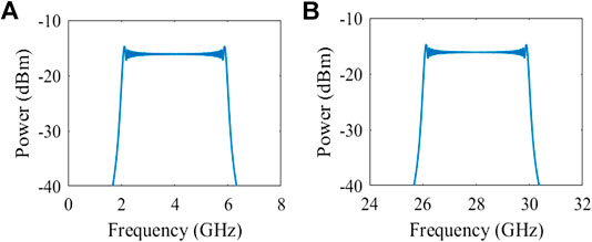
FIGURE 7. Spectra of original linearly-chirped signals with center frequencies of (A) 4 GHz and (B) 28 GHz.
According to Table 3, v-copy 2 and v-copy 4 were required for receiving the “low-frequency” linearly-chirped signal, where the CFs of the TOFs were set to 192.918 THz and 192.980 THz, and the bandwidths of the TOFs were 5 GHz. The spectra of the EQHs were plotted in Figure 8A. Because the TOFs are non-ideal in practice, the OC with the CF of 192.914 THz cannot be effectively suppressed. After heterodyne detection of the OC and the LO with the CF of 192.917 THz, a 3 GHz tone was generated which was shown in Figure 8A, i. After filtering by four 1-GHz LPFs, the 4-GHz dynamic signal was channelized into four 1 GHz sub-signals (δs = 1 GHz), where we assume that the LPFs had rectangular TPs. Moreover, the waveforms of the channelized sub-signal were depicted in Figure 8B, respectively.
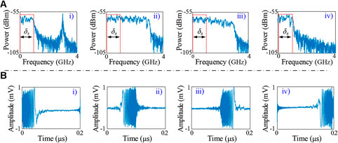
FIGURE 8. (A) Spectra of the output signals processed by optical hybrids and electrical quadrature hybrids and (B) waveforms of channelized signals after low-pass filters, where the 4 GHz linearly-chirped signal has a 4 GHz center frequency.
Similarly, the “high-frequency” linearly-chirped signal can also be received, where v-copy 1 and v-copy 3 were required. Moreover, the CFs of the TOFs should be set to 192.886 and 192.948 THz. The obtained spectra after processing by the EQHs and the waveforms of the channelized sub-signals were given in Figure 9.
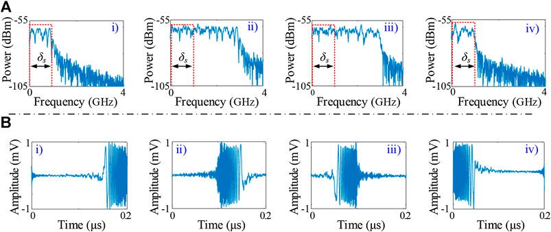
FIGURE 9. (A) Spectra of the output signals processed by optical hybrids and electrical quadrature hybrids and (B) waveforms of channelized signals after low-pass filters, where the 4 GHz linearly-chirped signal has a 28 GHz center frequency.
Based on the results shown in Figures 8, 9, the proposed channelized receiver can provide a much larger operative bandwidth by using the same number of devices when compared with the existing works in [23, 26–32]. Using two OHs, four BPDs, two EQHs, and four electrical LPFs, the equivalent operative bandwidth of the proposed multi-band channelized receiver can be up to 28 GHz. To the best of our knowledge, it is the first time that a photonics-assisted channelized receiver is built which doesn’t require knowing the spectrum information in advance.
Conclusions
In this work, based on the spectrum analysis and the coherent channelization, a photonics-assisted channelized receiver has been proposed for multi-band microwave signals. After determining the spectrum information by the spectrum analysis, the original wideband signal with dynamic microwave bands was received by the coherent channelization. For seven cases considered, the spectrum information can be obtained by monitoring the optical power in each sub-channel. Moreover, two 4 GHz linearly-chirped signals with CFs of 4 and 28 GHz have been channelized into four 1 GHz sub-channels and received, respectively. We equivalently can build a multi-band coherent channelizer that works for dynamic microwave signals by using a few devices. For scenarios requiring multi-band microwave signals such as modern radars, communication satellites, radio over fiber systems, and the 5th generation mobile network, the proposed photonics-assisted channelized receiver provides the low-complexity and low-cost implementation and shows a tremendous advantage and potential.
Data Availability Statement
All datasets presented in this study are included in the article.
Author Contributions
HH and CF conceived the method and conducted the model. HH, WZ, YC, and ZY contributed to the organization and writing of the manuscript. HH, CF, WZ, YC, HF, ZY, FC, and KQ did the revision and editing. All authors reviewed the manuscript.
Funding
Advance Research Project of Common Technology (No. 41418050102), Sichuan Science and Technology Foundation Program (No. 2018JY0145), Project for Innovation Team of Guangdong University (No. 2018KCXTD033), National Key R&D Program of China (no. 2018YFB1801302), Project for Zhongshan Key Social Public Welfare Science and Technology (No. 2019B2007), Zhongshan Government Foundation project for National Laboratory Zhongshan Branch Lab (No. 412S06), Zhongshan Innovative Research Team Program (No. 180809162197886), Zhongshan Institute high-level talent scientific research startup fund project (No. 416YKQ04).
Conflict of Interest
The authors declare that the research was conducted in the absence of any commercial or financial relationships that could be construed as a potential conflict of interest.
References
1. Zhang C, Huang H, Qiu K. Microwave photonics and its optical wireless access systems. In: Proceedings of fiber optic sensing and optical communication; 2018 December; Beijing, China; SPIE 10849. doi:10.1117/12.2505311
2. Li C, Peng Z, Huang T-Y, Fan T, Wang F-K, Horng T-S, et al. A review on recent progress of portable short-range noncontact microwave radar systems. IEEE Trans Microw Theor Tech (2017). 65:1692–706. doi:10.1109/TMTT.2017.2650911
3. Pan S, Zhu D, Liu S, Xu K, Dai Y, Wang T, et al. Satellite payloads pay off. IEEE Microw Mag (2015). 16:61–73. doi:10.1109/MMM.2015.2441619
4. José C, José M, Ivana G, Juan S, Juan L, Salvador S. Microwave photonic signal processing. J Lightwave Technol (2013). 31:571–86. doi:10.1002/9780470744857.ch8
5. Akyildiz IF, Nie S, Lin S-C, Chandrasekaran M. 5G roadmap: 10 key enabling technologies. Comput Network (2016). 106:17–48. doi:10.1016/j.comnet.2016.06.010
6. Zou X, Lu B, Pan W, Yan L, Stöhr A, Yao J. Photonics for microwave measurements. Laser Photon Rev (2016). 10:711–34. doi:10.1002/lpor.201600019
7. Brès C-S, Zlatanovic S, Wiberg AOJ, Radic S. Reconfigurable parametric channelized receiver for instantaneous spectral analysis. Opt Express (2011). 19:3531–41. doi:10.1364/OE.19.003531
8. Xie X, Dai Y, Ji Y, Xu K, Li Y, Wu J, et al. Broadband photonic radio-frequency channelization based on a 39-GHz optical frequency comb. IEEE Photon Technol Lett (2012). 24:661–3. doi:10.1109/lpt.2012.2185787
9. Huang H, Zhang C, Zhou H, Yang H, Yuan W, Qiu K. Double-efficiency photonic channelization enabling optical carrier power suppression. Opt Lett. (2018). 43:4073–6. doi:10.1364/OL.43.004073
10. Winnall ST, Lindsay AC, Austin MW, Canning J, Mitchell A. A microwave channelizer and spectroscope based on an integrated optical Bragg-grating Fabry-Perot and integrated hybrid Fresnel lens system. IEEE Trans Microw Theor Tech (2006). 54:868–72. doi:10.1109/TMTT.2005.863052
11. Huang H, Wang R, Zhang C, Chen Y, Yang H, Qiu K. Tunable ultra-flat optical-comb-enabled, reconfigurable, and efficient coherent channelized receiver. Opt Lett (2020). 45:848–51. doi:10.1364/ol.385458
12. Shin H, Harjani R. Low-power wideband analog channelization filter bank using passive polyphase-FFT techniques. IEEE J Solid State Circ (2017). 52:1753–67. doi:10.1109/JSSC.2017.2700792
13. Nguyen H-N, Kim K-S, Han S-H, Lee J-Y, Kim C, Lee S-G. A low-power interference-tolerance wideband receiver for 802.11af/ah long-range Wi-Fi with post-LNA active N-path filter. IEEE T Microw Theory (2018). 66:2287–98. doi:10.1109/TMTT.2018.2805341
14. Hao W, Dai Y, Yin F, Zhou Y, Li J, Dai J, et al. Chirped-pulse-based broadband RF channelization implemented by a mode-locked laser and dispersion. Opt Lett (2017). 42:5234–7. doi:10.1364/ol.42.005234
15. Khilo A, Spector SJ, Grein ME, Nejadmalayeri AH, Holzwarth CW, Sander MY, et al. Photonic ADC: overcoming the bottleneck of electronic jitter. Optic Express (2012). 20:4454–69. doi:10.1364/OE.20.004454
16. Strutz SJ, Williams KJ. An 8-18-GHz all-optical microwave downconverter with channelization. IEEE T Microw Theory (2001). 49:1992–5. doi:10.1109/22.954819
17. Wang W, Liu J, Sun W, Wang X, Zhu N. Channelization microwave frequency upconversion based on dual-parallel optical frequency comb generators. In: Proceedings of optoelectronic devices and integration; 2015 June; Wuhan, China. Vol. 2. (2015). doi:10.1364/OEDI.2015.OW2C.2
18. Zou X, Pan W, Luo B, Yan L. Photonic approach for multiple-frequency component measurement using spectrally sliced incoherent source. Opt Lett (2010). 35:438–41. doi:10.1364/OL.35.000438
19. Xu X, Wu J, Nguyen TG, Chu ST, Little BE, Morandotti R, et al. Broadband RF channelizer based on an integrated optical frequency Kerr comb source. J Lightwave Technol (2018). 36:4519–26. doi:10.1109/JLT.2018.2819172
20. Zhou H, Geng Y, Cui W, Huang S, Zhou Q, Qiu K, et al. Soliton bursts and deterministic dissipative Kerr soliton generation in auxiliary-assisted microcavities. Light Sci Appl (2019). 8:50. doi:10.1038/s41377-019-0161-y
21. Wang W, Davis RL, Jung TJ, Lodenkamper R, Lembo LJ, Brock JC, et al. Characterization of a coherent optical RF channelizer based on a diffraction grating. IEEE T Microw Theory (2001). 49:1996–2001. doi:10.1109/22.954820
22. Rhodes WT Acousto-optic signal processing: convolution and correlation. Proc IEEE (1981). 69: 65–79. doi:10.1109/PROC.1981.11921
23. Tang Z, Zhu D, Pan S. Coherent optical RF channelizer with large instantaneous bandwidth and large in-band interference suppression. J Lightwave Technol (2018). 36:4219–26. doi:10.1109/JLT.2018.2857500
24. Brès CS, Wiberg AOJ, Zlatanovic S, Radic S. Parametric channelized receiver for single-step spectral analysis. In: Optical fiber communication conference and exposition (OFC) and the national fiber optic engineers conference; 2011 March 6–10. Los Angeles, CA: NFOEC (2011). doi:10.1364/OFC.2011.OThC1
25. Brès CS, Wiberg AOJ, Zlatanovic S, Radic S. Characterization of parametric RF channelized receiver through time domain monitoring. In: Conference on lasers and electro-optics (CLEO); May 6–11 2012; San Jose, CA (2012).
26. Wiberg AOJ, Esman DJ, Liu L, Adleman JR, Zlatanovic S, Ataie V, et al. Coherent filterless wideband microwave/millimeter-wave channelizer based on broadband parametric mixers. J Lightwave Technol (2014). 32:3609–17. doi:10.1109/JLT.2014.2320445
27. Yang J, Li R, Dai Y, Dong J, Li W. Wide-band RF receiver based on dual-OFC-based photonic channelization and spectrum stitching technique. Optic Express (2019). 27:33194–204. doi:10.1364/OE.27.033194
28. Jiang W, Zhao S, Tan Q, Liang D, Li X, Gao Y. Wideband photonic microwave channelization and image-reject down-conversion. Opt Commun (2019). 445:41–9. doi:10.1016/j.optcom.2019.04.013
29. Xie X, Dai Y, Xu K, Niu, J, Wang R, Yan L, et al. Broadband photonic RF channelization based on coherent optical frequency combs and I/Q demodulators. IEEE Photonics J (2012). 4:1196–202. doi:10.1109/JPHOT.2012.2207380
30. Chen W, Zhu D, Xie C, Liu J, Pan S. Microwave channelizer based on a photonic dual-output image-reject mixer. Opt Lett (2019). 14:4052–5. doi:10.1364/OL.44.004052
31. Yang J, Li R, Mo Z, Dong J, Li W. Channelized photonic-assisted deramp receiver with an extended detection distance along the range direction for LFM-CW radars. Opt Express (2020). 28:7576–84. doi:10.1364/OE.386819
32. Xie C, Zhu D, Chen W, Pan S. Microwave photonic channelizer based on polarization multiplexing and photonic dual output image reject mixer. IEEE Access (2019). 7:158308–16. doi:10.1109/ACCESS.2019.2947673
33. Li R, Chen H, Yu Y, Chen M, Yang S, Xie S. Multiple-frequency measurement based on serial photonic channelization using optical wavelength scanning. Opt Lett (2013). 38:4781–4. doi:10.1364/OL.38.004781
34. Oleski PJ, Patton RW, Bharj SS, Thaduri M. Transmit receive module for space ground link subsystem (SGLS) and unified S-band (USB) satellite telemetry, tracking and commanding (TT and C), and communications. In: IEEE military communications conference; January 2004. Piscataway, NJ: IEEE (2004).
35. Shambayati S. The struggle for Ka-band: NASA's gradual move towards using 32-GHz Ka-band for deep space missions.In: IEEE aerospace conference; Apirl 2007. Big Sky, MT: Big Sky (2007).
36. Simone L, Salerno N, Maffei M. Frequency-hopping techniques for secure satellite TT&C: system Analysis & trade-offs. In: International workshop on satellite and space communications; October 2006; Madrid, Spain (2006).
37. Nguyen AT, Zhou H, Hadjitheodosiou M, Baras JS. A direct-to-ground architecture for supporting commercial communications from the International Space Station. In: IEEE international conference on communications; 2002 February. Piscataway, NJ: IEEE (2002).
38. Nguyen TK, Oh NJ, Cha CY, Oh YH, Ihm GJ, Lee SG. Image-rejection CMOS low-noise amplifier design optimization techniques. IEEE T Microw Theory (2005). 53:538–47. doi:10.1109/TMTT.2004.840744
39. Lee J, Li YA, Hung MH, Huang SJ. A fully-integrated 77-GHz FMCW radar transceiver in 65-nm CMOS Technology. IEEE J Solid State Circ (2010). 45:2746–56. doi:10.1109/JSSC.2010.2075250
40. Seimetz M, Weinert C. Options, feasibility, and availability of 2x4 900 hybrids for coherent optical systems. J Lightwave Technol (2006). 24:1317–22. doi:10.1109/JLT.2005.863251
Keywords: optical signal processing, optoelectronic device, spectrum analysis, radio frequency photonics, channelization
Citation: Huang H, Zhang C, Zheng W, Chen Y, Yang H, Yi Z, Chi F and Qiu K (2020) Photonics-Assisted Multi-Band Microwave Receiver Based on Spectrum Analysis and Coherent Channelization. Front. Phys. 8:562456. doi: 10.3389/fphy.2020.562456
Received: 15 May 2020; Accepted: 11 September 2020;
Published: 01 October 2020.
Edited by:
Olivier J. F. Martin, École Polytechnique Fédérale de Lausanne, SwitzerlandReviewed by:
Nirmal Mazumder, Manipal Academy of Higher Education, IndiaYoubin Yu, Zhejiang Sci-Tech University, China
Copyright © 2020 Huang, Zhang, Zheng, Chen, Yang, Yi, Chi and Qiu. This is an open-access article distributed under the terms of the Creative Commons Attribution License (CC BY). The use, distribution or reproduction in other forums is permitted, provided the original author(s) and the copyright owner(s) are credited and that the original publication in this journal is cited, in accordance with accepted academic practice. No use, distribution or reproduction is permitted which does not comply with these terms.
*Correspondence: Chongfu Zhang, WmhhbmdjZnpoYW5nQHVlc3RjLmVkdS5jbg==