 Denis Dauvergne1*
 Oreste Allegrini2
 Cairo Caplan3Xiushan Chen2
 Sébastien Curtoni1Ane Etxebeste2,4
 Marie-Laure Gallin-Martel1
 Maxime Jacquet1Jean Michel Létang4Jayde Livingstone1,2Sara Marcatili1
 Christian Morel3
 Étienne Testa2Yannick Zoccarato2
- 1Université Grenoble Alpes, CNRS/IN2P3, Grenoble INP, LPSC-UMR 5821, Grenoble, France
- 2Université de Lyon, Université Lyon 1, CNRS/IN2P3, Institut de Physique des Deux Infinis de Lyon, UMR 5822, Villeurbanne, France
- 3Aix-Marseille Univ, CNRS/IN2P3, CPPM, Marseille, France
- 4Université de Lyon, CREATIS, CNRS, UMR 5220, INSERM U1044, INSA-Lyon, Université Lyon 1, Centre Léon Bérard, Villeurbanne, France
Within the frame of the CLaRyS collaboration, we discuss the assets of using a reduced-intensity in vivo treatment control phase during one or a few beam spots at the beginning of a particle therapy session. By doing so we can improve considerably the conditions for secondary radiation detection and particle radiography. This also makes Time-of-Flight (ToF) resolutions of 100 ps rms feasible for both the transmitted particles and secondary radiations, by means of a single-projectile counting mode using a beam-tagging monitor with time and position registration. This opens up new perspectives for prompt-gamma timing and Compton imaging for range verification. ToF-based proton computed tomography (CT) and ToF-assisted secondary proton vertex imaging in carbon therapy are also discussed, although for the latter, no evidence of any benefit at small observation angles is anticipated. The reduction of the beam intensity during one or a few spots on the various accelerators for particle therapy should not significantly reduce the patient workflow.
Introduction
In vivo range verification in particle therapy remains an important challenge to improve the treatment quality. Indeed, uncertainties in the treatment planning, anatomical evolution between planning imaging and actual treatment fraction, patient positioning and moving, may cause deviations between planned dose and actual delivered dose. Thus, the beneficial impact of the ballistic precision is reduced by the necessity of additional security margins, and by limiting irradiation fields to those avoiding directions where organs at risk are located immediately behind the ion range [1, 2]. Several techniques are being intensively developed, either based on secondary radiation [Positron Emission Tomography (PET), Prompt-gamma (PG), ionoacoustic waves, bremsstrahlung], or on the improvement of planning imaging to get more accurate range prediction [2–8]. However, the implementation of in vivo range verification devices faces several issues. Among them, one needs to collect and treat sufficiently accurate data during the smallest possible fraction of the patient irradiation (ideally a single pencil beam spot), and get the relevant information in the shortest possible time, in order to continue with the treatment if safe conditions are met, or to minimize the consequences of a deviation. In addition, the device should comply with the environment of the treatment room, and the range verification procedure should not reduce the patient flow beyond the acceptable.
In the present paper, we propose to address these two issues of a real-time verification compatible with the clinical workflow, with the device that has been developed within the CLaRyS collaboration. We discuss on the opportunity offered by a reduced beam intensity for PG and ion imaging. More specifically, we focus on the assets of reducing the clinical beam intensity for a short period (one or a few beam spots in pencil beam scanning mode), in such a way that each single incident particle is identifiable, like in list-mode ion-CT, where all relevant information like upstream/downstream positions and directions, energy, is recorded for each projectile. First, this will relax important constraints on particle detection rates during beam delivery at clinical intensities [9, 10]. Second, fast Time-of-Flight (ToF) at the level of 100 ps rms may be used to improve existing modalities such as prompt-gamma Compton imaging, prompt-gamma timing, proton radiography, and secondary proton imaging. Third, we briefly discuss a few technical aspects of implementing a beam intensity reduction, which should not reduce significantly the patient flow.
Prompt-Gamma Range Verification
Prompt-gamma (PG) detection offers the unique opportunity for range verification in real time with a few-millimeter precision at a single proton pencil-beam spot scale [4]. Indeed, high-energy gamma rays (1–10 MeV range) are emitted within a very short time (mostly less than a picosecond) after inelastic collisions between primary protons and target nuclei, and may escape the patient body without further interaction. Although part of the PGs are also induced by secondary particles (e.g., neutrons), the PG emission profile is then correlated to the proton range. Several PG-based techniques are proposed to control the treatments. Prompt-gamma imaging (PGI) requires the directional detection of gamma rays, using either mechanical or electronic collimation (e.g., with Compton cameras). Range verification requires at least 1D imaging along the beam direction. Prompt-Gamma Peak Integral (PGPI) considers the integrated yields issued from the patient, with time-of-flight (ToF) selection [11]; it is connected to the energy deposited in the patient, and may provide 3D information about the beam path by using several detectors. Prompt-Gamma Timing (PGT) provides the ToF distribution that is correlated with the proton range [12]. Prompt-Gamma Spectroscopy (PGS) combines partial collimation to select part of the range in the field of view, and PG spectral information with good resolution, in order to extract information on chemical composition and range, from energy- and (A,Z)-nuclear-dependence of individual gamma emission-line probabilities [13]. ToF is necessary in PGS to enhance signal-to-background ratio.
For ions heavier than protons, PG detection is less performing since smaller amounts of projectiles are used to deliver the same physical and biological doses, and thus, treatment verification should be considered for larger amounts of incident particles than single spots.
All the PG-based detection methods face the issue of acquiring sufficient statistics within a short time, at high instantaneous count rate. Basically, in clinical conditions, a typical proton beam spot represents 107 particles that are delivered at an average intensity of 1010 protons/s at cyclotrons and synchro-cyclotrons dedicated to protons, i.e., within about 1 ms. This amount of protons per spot may vary by plus/minus one order of magnitude typically: it is higher for some distal spots [14], or when particular care is taken during the planning stage to boost spots dedicated to verification [15], and it is much smaller for proximal spots. For a 10 cm proton range in tissue equivalent matter, about 3% of the projectiles will generate primary PG by nuclear collisions [4]. A single detector with 3 × 10⁻³ absolute detection efficiency (e.g., a 100% intrinsic efficiency scintillator of 7.5 cm diameter located at 30 cm) would then detect 103 PG during 1 ms, at an instantaneous count rate of 106/s achieved with a proton beam flux of 1010 protons/s. Moreover, this count rate may be doubled if one accounts for other radiation species impinging the detector (secondary gamma rays, neutrons, etc.). On the one hand, this represents a challenge, as pointed out by Pausch et al. [9], since detectors need to cope with a counting rate varying from about 0 (beam pauses between spots) to more than 106 Hz during 1 ms almost without transient regimes. On the other hand, such a statistics of 103 counts would hold for fields of view covering the whole proton range (in the case of methods such as PGPI and PGT). If the detection system is aimed at imaging the PG fall-off close to the Bragg peak, then the statistics in the restricted area of interest is reduced accordingly. The precision of the fall-off retrieval is proportional to the contrast-to-noise ratio [16], and thus to , where NPG is the number of detected PG in the region of interest. Passive collimation reduces the flux of incoming PG on a detector, yielding to low detection efficiency, without substantial reduction of the neutron background if ToF is not implemented. Thus, large detection volumes with segmented readout are necessary, like for the knife-edge-slit camera developed by IBA and Politecnico-Milano [17] that has been used in clinics. This shifts the issue of count rate per detector to a large acquisition-flow handling. Compton imaging may yield to higher detection efficiency than collimated devices. However, at clinical beam intensity, the coincidence rate between the two detection stages is dominated by fortuitous coincidence events induced by quasi-simultaneous projectiles [10, 18, 19]. A significant reduction of the incident flux is needed in order to minimize this background source [10], at the level of one incident proton within the duration of the time-coincidence window, unless efficient filtering strategies are used, which has not been demonstrated so far.
Going further, the reduction of the incident beam intensity to a level where individual projectile identification is possible, presents not only the asset of better PG detection conditions but also the opportunity for high-resolution ToF. Basically, 1–2 ns ToF resolution makes it possible to select PG issued from a patient, and to discriminate them from massive particles like neutrons at sufficiently large distances, at the scale of a proton bunch delivered by a cyclotron (of the order of 1 ns). This is the strategy used for the PGPI technique and in the development of PGT at Oncoray. However, in the latter case, this bunch length is the main limitation of the accuracy of PGT [20, 21] at clinical beam intensities. The reduction of the ToF resolution down to 100 ps rms would translate to a PG vertex position determination of 1–2 cm rms resolution (observation at 90°), proportional to the proton velocity: indeed, 1 cm rms holds for β = v/c = 0.3, i.e., 3 cm from the end of the proton range. Note that this resolution depends on the observation angle: it is smaller at backward angles, for which proton-to-vertex and photon-to-detector transit times are adding, both increasing monotonically with the vertex depth. Such resolution is typically the same as the point spread response of a multi-collimated camera [17, 22] or a Compton camera [23], without any collimation.
Prompt Gamma Timing
Recently, Marcatili et al. published first results on PGT with about 100 ps rms ToF resolution, using fast monolithic scintillators and a diamond-detector beam trigger [24]. They estimated the achievable probability with 95% confidence level to detect a 3-mm thickness variation of an air cavity in a PMMA phantom with 108 incident protons and a single detector having a detection efficiency of 1.5 × 10⁻³. In order to illustrate the asset of such 100 ps time-resolution in single proton counting mode, Figure 1 compares the results derived from PGT with 162 MeV proton beams at clinical intensities (in bunch-counting mode with >102 protons/bunch, where the ToF is measured between a detected PG relative to the accelerator HF signal) from Werner et al. [21] and those obtained in Marcatili et al. [24] with 68 MeV protons in single incident particle regime (i.e., the ToF is measured relative to the arrival of the single proton that induced the PG). In the first case, a 2-cm air cavity is inserted in a PMMA phantom at 9 cm depth. In the latter case, a 2.5 cm thick air gap is inserted at 1 cm depth. In the bunch-counting mode, the effect of the air cavity results in a shift of the mean value and a broadening of the PGT spectrum, as observed from the difference between both the colored curves. However, the width of the time distribution is dominated by the pulse duration (~3 ns FWHM). In contrast, the shape of the distribution in single proton counting mode reflects mainly the flight time of a proton inside the target (of the order of 1 ns), and the air insert is clearly observed as a separation of two components in the PGT distribution in the target. In addition, the authors of ref. [21] mentioned that the large statistical fluctuations observed were caused by the limited statistics available for a single beam spot. Single counting mode makes it possible to improve the statistics by reducing dead-time and improving the detection solid angle with closer detectors. This is also illustrated in Figure 1, where both spectra were acquired with similar numbers of incident protons (of the order of one large beam spot).
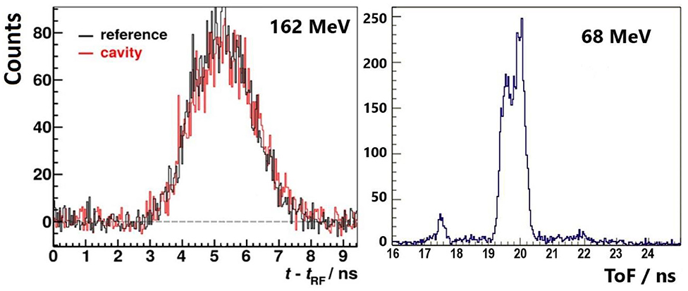
Figure 1. Experimental prompt-gamma timing spectra obtained with proton beams in PMMA targets; (Left) at clinical intensity, with synchronization to the cyclotron RF signal (pulse by pulse basis for a single beam spot of 3.8 × 10⁸ protons, data from [21] with authors permission, with and without a 2 cm air cavity at 9 cm depth); (Right) ion-per-ion basis at 68 MeV, using a diamond beam trigger at low intensity, a 2.5 cm thick air insert is located at 1 cm from the target entrance. The number of protons used to generate the second histogram is similar (~3 × 10⁸) [24].
Compton Prompt-Gamma Imaging
In the frame of the CLaRyS collaboration project, a large area Compton camera has been designed [23], the sizes and detection geometry of which are reported in Figure 2A. Compton reconstructible events consist in a single Compton scattering in the first stage (7 planes of 9 × 9 × 0.2 cm3 position-sensitive silicon detectors) followed by total or partial absorption of scattered photons in a 38 × 38 × 3 cm3 pixellated-BGO scintillator absorber. A beam hodoscope is used to measure the beam-transverse position and time of arrival. Therefore, the Compton cone, whose axis is the line joining the interaction vertices in the scatterer and absorber stages, and whose angle is determined by the energy deposited in both the stages in the case of full absorption, intersects the beam trajectory in two points. Actually, the two solutions are not points, but correspond to extended zones, which size depends on (i) the beam extension in the transverse plane due to beam size and lateral scattering, (ii) the CC spatial resolution [10]. The latter depends on the spatial and energy resolutions of both the scatter and absorber detectors, and on the Doppler broadening corresponding to the electron Compton profiles of the scattering material (the heavier material, the larger angular broadening of the cone [25]). The expected spatial resolution of the Compton camera for a point source, polychromatic PG energy spectrum is 8.3 mm FWHM [23].
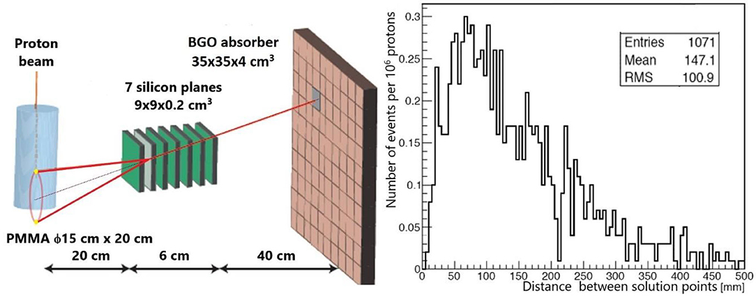
Figure 2. (Left) scheme of the CLaRyS Compton camera used for range verification in simulations for 160 MeV protons. The two yellow points represent two line-cone intersection points. (Right) using this geometry, distribution of distances between the two line-cone intersection points deduced from Compton kinematics in the case of an interaction in each stage of the camera (data from [26]).
Among the two intersection points (or volumes), one is the correct vertex, provided full absorption occurred in the absorber. The second one will contribute to background if not rejected by basic considerations (e.g., when located outside the target). Using this line-cone intersection method, no time-consuming reconstruction algorithm is required if one could identify the right point among the two intersection points. Figure 2B represents, for the particular geometry shown in Figure 2A, the simulated distribution of distances separating the two solution-points [26]. The camera axis is centered at 10 cm proton penetration depth, and the distance between the beam and the scatter detector is 20 cm. The average value of the distribution is 14.7 cm, i.e., of the same order of magnitude as the proton range (~14.8 cm at 160 MeV [27]). Their corresponding transient time in the PMMA phantom is 1.3 ns. This distance is much larger than the extension of the line-cone intersection volumes due to spatial resolution. Thus, it is expected that a detector time resolution of a few hundreds of ps will make it possible to identify the right solution. These expectations are confirmed in a forthcoming paper by our collaboration, showing that the precision of the PG fall-off retrieval reaches the one obtained with a state-of-art iterative reconstruction algorithm, when ToF selection is used at 200 ps rms resolution or less.
Ion Radiography
The basic idea of ion radiography is to measure the relative stopping power of the traversed material, and thus the Water Equivalent Thickness (WET), by means of the energy loss of transmitted ions, either by calorimetry, or by the residual range in a reference material [28]. This energy loss is tightly connected to the electronic density, which makes ion radiography relevant for particle treatment planning, without uncertainty in the conversion factor between X-ray absorption and electronic density (Hounsfield units). Thus, ion tomography may improve the precision of planning imaging, currently performed with X-ray CT, if an overall advantage is obtained by combining the following criteria: (i) minimize the induced dose, (ii) minimize the exposition time at the particle treatment place, (iii) optimize spatial resolution, and (iv) optimize accuracy on WET. For the latter criterion, the necessary precision on the energy loss measurement is below 1% [28], which requires appropriate calorimetry or residual range determination. The spatial resolution is conditioned by particle tracking, but is inherently limited by multiple scattering inside the patient. Two strategies may be followed: either spot-by-spot or single particle tracking [29, 30]. The integration mode with spot by spot tracking presents the advantage of a simplified tracking device, but the disadvantage of poorer spatial resolution, caused by the initial spot size, and the consequent indetermination of the path in the case of mixed-fields, i.e., when various integrated electronic densities are met within the same spot, due to varying structures in the transverse plane. Gianoli et al. compared the two methods in proton radiography, using the Most Likely Path (MLP) reconstruction algorithms. They have shown that the additional blurring caused by the spot size can be at least partially compensated at the cost of a higher statistics, hence a higher dose, relative to single proton tracking [29]. For carbon ion radiography, with reduced scattering relative to protons, Meyer et al. have shown that with the integration mode, performance approaching those of the list mode could be obtained [31]. However, the list mode remains the gold standard for proton or ion radiography for optimizing the spatial resolution, at the expense of a beam intensity compatible with single particle detection.
In the list mode option, the information on the energy loss inside the patient could be obtained from ToF, provided large enough distances between the patient and the downstream detector are used. Indeed, measuring small variations of the transient time inside the patient is out of reach, since this time is of the order of 1–2 ns: 1% resolution in the energy loss would translate into a 5–10 ps time resolution. However, a ToF detector may measure variations of the residual velocity. For particles exiting the patient at typically 1/3 of the speed of light, 1% of kinetic energy variation corresponds to 100 ps flight time variation over 2 m. Thus, it appears feasible to design a proton-CT device based on fast trackers, optimized for low residual energies. The asset of such a device is a simplified detector for spatial and time measurement relative to separate tracking and calorimetry detectors. Recently, Worstell et al. [32] published a first progress report on the development of a ToF-based proton radiography device: fast position sensitive detectors (large area micro-channel plates) are used to track particles with a time resolution that is expected to be smaller than 100 ps.
Secondary Proton Imaging
This technique consists in the detection of secondary light charged particles (proton and its isotopes deuteron and tritium) under irradiation with heavier ions (helium or heavier ions) [33–36]. Such particles are created with a high probability during quasi-elastic and inelastic collisions. Figure 3 shows a simulated energy distribution of protons at emission in a thin PMMA target by incident carbon ions at three different energies [37]. The energy spectrum is quite broad, but only high energy secondary protons have a chance in practice to escape from the patient body (100 MeV protons have a range of 75 mm in water [27]). For the high-energy part of the distributions, one may observe a maximum at velocities that are close to the carbon projectile velocity. However, the velocity distribution above that threshold is still very large. Thus, protons that are detected outside a patient are more likely emitted from the entrance than close to the end of range. In addition, protons emitted from the entrance region will reach the exit before those emitted in depth, due to the combined effect of higher slowing-down of carbon ions before the vertex, and the higher average proton velocity during their path to exit. Simulations have shown that, in the case of 200 MeV/u carbon ions incident on a head phantom, the correlation between ToF and vertex position is not sufficient to improve significantly the vertex localization obtained by tracking at low observation angle (10°), when considering ToF information. This is due to the broad proton energy distribution as shown in Figure 3, but also to the fact that carbon ions and secondary protons do not have sufficiently different velocities at the emission point. Moreover, like for PG, observation at small forward angles is not a favorable case for ToF discrimination because the total path length of primary plus secondary particle is the same whatever the vertex position. Observation at larger angles, like in the INSIDE design (60°) [38, 39], or even at 90° [40], could be more favorable, because path lengths—and therefore ToF–are increasing with depth. However, one has to keep in mind that emission yields per solid angle unit drop down dramatically when the angle increases [37], which raises statistics issues for a small number of spots. This remains an open question.
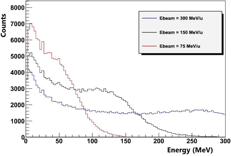
Figure 3. Geant4 simulation of the energy distribution of secondary protons at emission inside a thin PMMA target by carbon ions at three different energies. Nuclear reactions are modeled with the QMD model (data from [33]).
Need For A Beam Tagging System
Without using a beam monitor, the temporal resolution of the synchronization between the accelerator HF and the detection of prompt secondary particles at the patient place is limited to the bunch duration at the exit of the accelerator, convolved with the time dispersion due to the longitudinal momentum spread during beam transport. This is independent of the beam intensity. The bunch duration depends on the accelerator type: it is typically about 1 ns for a cyclotron, 8 ns for a synchro-cyclotron, and 20–50 ns for a synchrotron [4]. Moreover, the passive degradation of the energy between two different beam spots induces a time phase shift relative to the accelerator HF for an isochronous accelerator. This makes a time calibration necessary for each energy change. Therefore, a beam tagging system can be used advantageously to detect the time of arrival of ions on the patient, provided it is able to cope with high counting rates, either in clinical-intensity bunch modes, or in single particle counting regime. For bunch detection, secondary particle detectors can be used [20, 41], whereas scintillator-based hodoscopes are generally proposed for single particle counting, with timing resolutions of several hundred picoseconds [39, 42]. Thin ultra-fast silicon detectors (UFSD) have been explored for such purpose [43]. Using another technology, we have shown that a temporal resolution close to 100 ps rms is expected by means of diamond detectors, on condition that large areas are available with detector-grade crystals [24, 44]. Relatively large polycrystalline diamonds are available and provide such a time resolution for highly ionizing particles such as carbon ions. However, high energy protons may require high-quality single-crystals to reach both the detection efficiency and the good time resolution. A diamond beam-hodoscope is under construction by our collaboration. Such a beam tagging system has necessarily a finite thickness and will be located upstream from the patient. The impact on range shift (about 2 mm WET) needs to be accounted for in the treatment planning system, and the impact on secondary radiation additional dose corresponds to the same 2 mm WET. The distance between hodoscope and patient should be kept as small as possible to minimize the impact of multiple scattering, with the constraint of being compatible with the patient positioning system.
Beam Intensity Reduction
Reduction Factors and Possible Irradiation Delay
The beam intensity reduction should satisfy two criteria: first, the beam tagging system should handle all the incident particles and provide time stamp with the requested resolution. This requires typically 10 ns between two consecutive signals in a single readout channel. This can be achieved by means of detector segmentation anyway (for instance, 0.25 mm2 pixel size is requested for a flux of 4 × 10¹⁰ proton/cm2/s). Second, non-ambiguous assignment of the secondary particle detection to the primary projectile should be obtained. Depending on the observation distance and ToF resolution, this condition will constrain a second trigger probability on the hodoscope to a negligible value within a period of 1 to 5 ns.
At clinical proton beam intensities, the average beam intensity is about 2 nA during an irradiation spot, i.e. 1.2 × 10¹⁰ proton/s over 1–10 ms. At least 1 ms is required to shift between two adjacent spots (magnetic scanning), and more to change the energy (insertion of degrader device, or change of synchrotron energy). For carbon ions, the intensity is typically 107-108 ions/s at European synchrotron systems, up to 3 × 10⁸ ions/s at SAGA-HIMAT [45–47]. About 105 ions are needed for a single spot, with the same duration as for protons.
All accelerated beams have a pulsed structure at the nanosecond time scale (which we refer to as nanopulse structure below), which may be superimposed to the microsecond, or even second–scale pulse structure on synchro-cyclotrons and synchrotrons. For a 100 MHz cyclotron with around 1 ns pulse duration, the above condition corresponds to a probability of having one particle per pulse to be one order of magnitude larger than the probability to have more than one particle per pulse [p(1) > 10 × p(N>1)]. Assuming a Poisson distribution, this leads to a maximum average number of particles per pulse of 0.2. Relative to proton therapy intensities, this is a reduction by a factor of 1/1,000. For a proton synchro-cyclotron like IBA-S2C2, around 8 ns nanopulses are extracted with a period of 16 ns and 2 protons could be considered within the same nanopulse: indeed this should lead to identifiable events in most cases with a segmented detector. Thus, the average number of protons per pulse could be slightly higher than 0.2 (about 0.5). The reduction factor compared to clinical intensity is then a factor 1/10,000. As for synchrotrons, they have longer nanopulse durations (20–50 ns) which depend on the ion species. Correspondingly, the average number of particles per pulse should be about 2–5. This represents almost no reduction relative to clinical intensity in the case of carbon therapy (at 107 ions/s), and a factor smaller than 1/100 for proton therapy.
A reduction of the beam intensity during one or a few pencil-beam spots will extend the duration of the spot delivery, but not the time needed to change the spot position or energy. Thus, an intensity reduction by 1/1,000 will extend the spot duration by 0.5 s for a 107-proton-spot relative to a 2 nA-nominal intensity cyclotron. For a proton synchro-cyclotron, the extension is larger (5 s per spot). For a synchro-cyclotron delivering protons at 0.1 nA nominal intensity, the extension is also 1 s per spot. For carbon therapy, the extension of spot duration will be at the level of milliseconds, if any.
Monitoring the dose delivered at low intensity with a system compatible with high-intensity dose monitoring may represent an issue. Current monitoring devices are based on ionization chambers, like the IC2/3 that have been developed for proton therapy with IBA-cyclotrons [48, 49]. The sensitivity of this detector technology is of the order of several hundreds of protons per monitor unit and the signal/noise ratio with low beam intensity could be an issue. Therefore, the effect of large dark current on the control of the beam fluence and position and other noise source like radiophonic noise would need to be evaluated. Nevertheless, as the total charge to be integrated during a beam spot is unchanged when intensity varies, we expect that the electronic noise will not be a problem for beam fluence control at low particle rate. Additionally, such ionization chambers may work at pA currents for proton beams and have been calibrated for a wide range of dose rate (0.5–8 Gy/min) [49].
Technical Implementation of Beam Intensity Reduction
The easiest way to proceed to a beam reduction without changing any other characteristics (energy, time structure and emittance) is the insertion of a kind of pepper pot device [50] at the accelerator injection. The reduction factor is known and reproducible since it depends only on the geometry of the inserted filter. Insertion/extraction is fast, and no activation is generated, since particles have an energy of a few tens of keV at this stage. However, some compact injection geometries cannot make possible the insertion of such a device. Thus, a possibility would consist in stacking the accelerated beam at fixed frequency with the same number of particles as in normal operation, and use a slow extraction mode of the whole spill with an appropriate field. This procedure is possible with a synchrotron or a synchro-cyclotron [Mandrillon, personal communication]. In this case, no additional injection should be necessary, since a single spill contains enough particles for a single beam spot. Both strategies have the advantage of using all accelerated particles, which does not induce additional activation.
Discussion and Conclusion
We propose to implement a reduced-intensity, in vivo and real-time treatment control phase at the beginning of a particle therapy session. By achieving a single projectile counting mode with a beam tagging monitor, with time and position registration, one can improve considerably the conditions for secondary radiation detection and particle radiography. The first consequence is a reduction of the detection rate during beam delivery, which may considerably improve the quality of the data acquisition: reduction of dead-time, improvement of signal-to-background ratio, reduction/suppression of transient regimes. Moreover, the beam hodoscope provides directly the time of arrival of ions at the patient position, without calibration at each energy change.
More specifically, ToF resolutions of 100 ps rms can be achieved. This has a strong impact on PG imaging, since an information of 100 ps ToF directly translates into a position information of about 1 cm close to the PG fall-off. This opens up new perspectives for PG timing and Compton imaging. ToF proton-CT has been proposed and is being investigated by other groups. A potential benefit of ToF for secondary proton imaging in carbon therapy needs further investigations at large observation angles.
Besides this, other techniques like in-beam PET or ionoacoustic ultra-sound imaging would rather benefit from intense bunches with low duty cycle: maximization of the radiation source during a short time, and long time for signal collection (acoustic wave propagation and detection) and statistic accumulation (e.g., short-lived beta+ emission with few ms lifetime). Therefore, beam intensity reduction is not favorable for such techniques.
The reduction of the beam intensity during one or a few spots on the various accelerators for particle therapy should induce delays of the irradiation of the order of seconds at maximum, and therefore will not significantly reduce the patient workflow.
Data Availability Statement
The raw data supporting the conclusions of this article will be made available by the authors, without undue reservation.
Author Contributions
All authors belong to the CLaRyS collaboration. They have contributed to the instrumental, experimental, or simulation work that has led to the contents of this article. They meet at least one of the four authorship criteria following International Committee of Medical Journal Editors (ICMJE) recommendations. DD is the main writer of the text. All authors have contributed to the amendments of the text. They gave their consent on the final version.
Funding
The authors acknowledge the support from ITMO-Cancer (CLaRyS-UFT project) and LAbEx PRIMES (ANR-11-LABX-0063).
Conflict of Interest
The authors declare that the research was conducted in the absence of any commercial or financial relationships that could be construed as a potential conflict of interest.
Acknowledgments
This work is carried out in the frame of Labex PRIMES (ANR-11-LABX-0063) and within the framework of the EU Horizon 2020 project RIA-ENSAR2/MediNet (654 002). The authors would like to thank J.-M. Fontbonne for helpful discussion about ionization chamber operation vs. beam intensity and Pierre Mandrillon about the intensity reduction at synchro-cyclotrons.
References
1. Paganetti H. Range uncertainties in proton therapy and the role of Monte Carlo simulations. Phys Med Biol. (2012) 57:R99–117. doi: 10.1088/0031-9155/57/11/R99
2. Knopf AC, Lomax A. in vivo proton range verification: a review. Phys Med Biol. (2013) 58:R131–60. doi: 10.1088/0031-9155/58/15/R131
3. Kraan AC. Range verification methods in particle therapy: underlying physics and monte carlo modeling. Front Oncol. (2015) 5:150. doi: 10.3389/fonc.2015.00150
4. Krimmer J, Dauvergne D, Létang JM, Testa É. Prompt-gamma monitoring in hadrontherapy: a review. Nucl Instum Methods Phys Res Section A. (2018) 878:58–73. doi: 10.1016/j.nima.2017.07.063
5. Parodi K, Polf JC. in vivo range verification in particle therapy. Med Phys. (2018) 45:e1036–50. doi: 10.1002/mp.12960
6. Parodi K. Latest developments in in-vivo imaging for proton therapy. BJR. (2019) 93:20190787. doi: 10.1259/bjr.20190787
7. Xie Y, Bentefour H, Janssens G, Smeets J, Stappen FV, Hotoiu L, et al. Prompt gamma imaging for in vivo range verification of pencil beam scanning proton therapy. Int J Radiat Oncol Biol Phys. (2017) 4:27. doi: 10.1016/j.ijrobp.2017.04.027
8. Ferrero V, Fiorina E, Morrocchi M, Pennazio F, Baroni G, Battistoni G, et al. Online proton therapy monitoring: clinical test of a Silicon-photodetector-based in-beam PET. Sci Rep. (2018) 8:4100. doi: 10.1038/s41598-018-22325-6
9. Pausch G, Berthold J, Enghardt W, Römer K, Straessner A, Wagner A, et al. Detection systems for range monitoring in proton therapy: needs and challenges. Nucl Instum Methods Phys Res Section A. (2020) 954:161227. doi: 10.1016/j.nima.2018.09.062
10. Fontana M, Ley JL, Dauvergne D, Freud N, Krimmer J, Létang JM, et al. Monitoring ion beam therapy with a compton camera: simulation studies of the clinical feasibility. IEEE Trans Radiat Plasma Med Sci. (2020) 4:218–32. doi: 10.1109/TRPMS.2019.2933985
11. Krimmer J, Angellier G, Balleyguier L, Dauvergne D, Freud N, Herault J, et al. A cost-effective monitoring technique in particle therapy via uncollimated prompt gamma peak integration. Appl Phys Lett. (2017) 110:154102. doi: 10.1063/1.4980103
12. Golnik C, Hueso-González F, Müller A, Dendooven P, Enghardt W, Fiedler F, et al. Range assessment in particle therapy based on prompt γ-ray timing measurements. Phys Med Biol. (2014) 59:5399–422. doi: 10.1088/0031-9155/59/18/5399
13. Joost M, Verburg JS. Proton range verification through prompt gamma-ray spectroscopy. Phys Med Biol. (2014) 59:7089–106. doi: 10.1088/0031-9155/59/23/7089
14. Grevillot L, Bertrand D, Dessy F, Freud N, Sarrut D. A monte carlo pencil beam scanning model for proton treatment plan simulation using GATE/GEANT4. Phys Med Biol. (2011) 56:5203–19. doi: 10.1088/0031-9155/56/16/008
15. Tian L, Landry G, Dedes G, Kamp F, Pinto M, Niepel K, et al. Toward a new treatment planning approach accounting for in vivo proton range verification. Phys Med Biol. (2018) 63:215025. doi: 10.1088/1361-6560/aae749
16. Roellinghoff F, Benilov A, Dauvergne D, Dedes G, Freud N, Janssens G, et al. Real-time proton beam range monitoring by means of prompt-gamma detection with a collimated camera. Phys Med Biol. (2014) 59:1327–38. doi: 10.1088/0031-9155/59/5/1327
17. Perali I, Celani A, Bombelli L, Fiorini C, Camera F, Clementel E, et al. Prompt gamma imaging of proton pencil beams at clinical dose rate. Phys Med Biol. (2014) 59:5849–71. doi: 10.1088/0031-9155/59/19/5849
18. Ortega PG, Torres-Espallardo I, Böhlen TT, Cerutti F, Chin MPW, Ferrari A, et al. Noise evaluation of prompt-gamma technique for proton-therapy range verification using a Compton Camera. In: 2013 IEEE Nuclear Science Symposium and Medical Imaging Conference (Seoul). (2013). p. 1–7. Available online at: https://ieeexplore.ieee.org/document/6829310
19. Rohling H, Priegnitz M, Schoene S, Schumann A, Enghardt W, Hueso-González F, et al. Requirements for a compton camera for in vivo range verification of proton therapy. Phys Med Biol. (2017) 62:2795–811. doi: 10.1088/1361-6560/aa6068
20. Petzoldt J, Roemer KE, Enghardt W, Fiedler F, Golnik C, Hueso-González F, et al. Characterization of the microbunch time structure of proton pencil beams at a clinical treatment facility. Phys Med Biol. (2016) 61:2432–56. doi: 10.1088/0031-9155/61/6/2432
21. Werner T, Berthold J, Hueso-González F, Koegler T, Petzoldt J, Roemer K, et al. Processing of prompt gamma-ray timing data for proton range measurements at a clinical beam delivery. Phys Med Biol. (2019) 64:105023. doi: 10.1088/1361-6560/ab176d
22. Pinto M, Dauvergne D, Freud N, Krimmer J, Letang JM, Ray C, et al. Design optimisation of a TOF-based collimated camera prototype for online hadrontherapy monitoring. Phys Med Biol. (2014) 59:7653–74. doi: 10.1088/0031-9155/59/24/7653
23. Roellinghoff F, Richard MH, Chevallier M, Constanzo J, Dauvergne D, Freud N, et al. Design of a Compton camera for 3D prompt-[gamma] imaging during ion beam therapy. Nucl Instr Methods Phys Res Section A. (2011) 648:S20–2. doi: 10.1016/j.nima.2011.01.069
24. Marcatili S, Collot J, Curtoni S, Dauvergne D, Hostachy JY, Koumeir C, et al. Ultra-fast prompt gamma detection in single proton counting regime for range monitoring in particle therapy. Phys Med Biol. (2020). [Epub ahead of print].
25. Fontana M, Dauvergne D, Létang JM, Ley JL, Testa É. Compton camera study for high efficiency SPECT and benchmark with anger system. Phys Med Biol. (2017) 62:8794–812. doi: 10.1088/1361-6560/aa926a
26. Ley JL. Mise en Oeuvre d'un Démonstrateur de Caméra Compton Pour L'imagerie en Médecine Nucléaire et Pour le Contrôle en Temps Réel de L'hadronthérapie à L'aide des Rayonnements Gamma Prompts (Thesis). Univ. Lyon 1 (2015). Available online at: http://www.theses.fr/2015LYO10334 (accessed May 11, 2017).
27. Ziegler JF, Ziegler MD, Biersack JP. SRIM – the stopping and range of ions in matter (2010). Nucl Instrum Methods B. (2010) 268:1818–23. doi: 10.1016/j.nimb.2010.02.091
28. Johnson RP. Review of medical radiography and tomography with proton beams. Rep Prog Phys. (2017) 81:016701. doi: 10.1088/1361-6633/aa8b1d
29. Gianoli C, Meyer S, Magallanes L, Paganelli C, Baroni G, Parodi K. Analytical simulator of proton radiography and tomography for different detector configurations. Phys Med Eur J Med Phys. (2019) 59:92–9. doi: 10.1016/j.ejmp.2019.03.002
30. Krah N, Khellaf F, Létang JM, Rit S, Rinaldi I. A comprehensive theoretical comparison of proton imaging set-ups in terms of spatial resolution. Phys Med Biol. (2018) 63:135013. doi: 10.1088/1361-6560/aaca1f
31. Meyer S, Gianoli C, Magallanes L, Kopp B, Tessonnier T, Landry G, et al. comparative monte carlo study on the performance of integration- and list-mode detector configurations for carbon ion computed tomography. Phys Med Biol. (2017) 62:1096–112. doi: 10.1088/1361-6560/aa5602
32. Worstell WA, Adams BW, Aviles M, Bond J, Cascio E, Cremer T, et al. First results developing time-of-flight proton radiography for proton therapy applications. In: Medical Imaging 2019: Physics of Medical Imaging (International Society for Optics and Photonics). p. 109480G.
33. Amaldi U, Hajdas W, Iliescu S, Malakhov N, Samarati J, Sauli F, et al. Advanced quality assurance for CNAO. Nucl Instr Methods Phys Res Section A. (2010) 617:248–9. doi: 10.1016/j.nima.2009.06.087
34. Henriquet P, Testa E, Chevallier M, Dauvergne D, Dedes G, Freud N, et al. Interaction vertex imaging (IVI) for carbon ion therapy monitoring: a feasibility study. Phys Med Biol. (2012) 57:4655–69. doi: 10.1088/0031-9155/57/14/4655
35. Gwosch K, Hartmann B, Jakubek J, Granja C, Soukup P, Jäkel O, et al. Non-invasive monitoring of therapeutic carbon ion beams in a homogeneous phantom by tracking of secondary ions. Phys Med Biol. (2013) 58:3755–73. doi: 10.1088/0031-9155/58/11/3755
36. Piersanti L, Bellini F, Bini F, Collamati F, Lucia ED, Durante M, et al. Measurement of charged particle yields from PMMA irradiated by a 220 MeV/u 12 C beam. Phys Med Biol. (2014) 59:1857. doi: 10.1088/0031-9155/59/7/1857
37. Reithinger V. Assurance Qualité des Traitements par Hadronthérapie Carbone Par Imagerie de Particules Promptes Chargées. (Thesis). Univ. Lyon 1 (2015). Available online at: https://tel.archives-ouvertes.fr/tel-01441452/document (accessed May 11, 2017).
38. Marafini M, Attili A, Battistoni G, Belcari N, Bisogni MG, Camarlinghi N, et al. The INSIDE project: innovative solutions for in-beam dosimetry in hadrontherapy. Acta Physica Polonica A. (2015) 127:1465–7. doi: 10.12693/APhysPolA.127.1465
39. Traini G, Mattei I, Battistoni G, Bisogni MG, De Simoni M, Dong Y, et al. Review and performance of the dose profiler, a particle therapy treatments online monitor. Physica Medica. (2019) 65:84–93. doi: 10.1016/j.ejmp.2019.07.010
40. Battistoni G, Collamati F, De Lucia E, Faccini R, Marafini M, Mattei I, et al. Design of a tracking device for on-line dose monitoring in hadrontherapy. Nucl Instr Methods Phys Res Section A. (2017) 845:679–83. doi: 10.1016/j.nima.2016.05.095
41. Magalhaes Martins P, Dal Bello R, Seimetz M, Hermann G, Kihm T, Seco J. A single-particle trigger for time-of-flight measurements in prompt-gamma imaging. Front Phys. (2020) 8:169. doi: 10.3389/fphy.2020.00169
42. Krimmer J, Chevallier M, Constanzo J, Dauvergne D, Rydt MD, Dedes G, et al. Collimated prompt gamma TOF measurements with multi-slit multi-detector configurations. J Instru. (2015) 10:P01011. doi: 10.1088/1748-0221/10/01/P01011
43. Vignati A, Monaco V, Attili A, Cartiglia N, Donetti M, Mazinani MF, et al. Innovative thin silicon detectors for monitoring of therapeutic proton beams: preliminary beam tests. J Inst. (2017) 12:C12056. doi: 10.1088/1748-0221/12/12/C12056
44. Gallin-Martel M-L, Abbassi L, Bes A, Bosson G, Collot J, Crozes T, et al. A large area diamond-based beam tagging hodoscope for ion therapy monitoring. EPJ Web Conf. (2018) 170:09005. doi: 10.1051/epjconf/201817009005
45. Kanazawa M, Endo M, Himukai T, Kitamura M, Mizota M, Nakagawara A, et al. Scanning Irradiation System at SAGA-HIMAT. In: Proceedings of IPAC2017 (Copenhagen, Denmark), 4698–700. Available at: https://accelconf.web.cern.ch/IPAC2017/papers/thpva101.pdf
46. Colautti P, Conte V, Selva A, Chiriotti S, Pola A, Bortot D, et al. Microdosimetric study at the cnao active-scanning carbon-ion beam. Radiat Prot Dosimetry. (2018) 180:157–61. doi: 10.1093/rpd/ncx217
47. Krantz C, Cee R, Faber F, Feldmeier E, Fischer T, Galonska M, et al. Slow extraction techniques at the marburg ion-beam therapy centre. In: Proceedings of the 9th International Particle Accelerator Confernce. Vancouver, BC (2018).
48. Patera V, Sarti A. Recent advances in detector technologies for particle therapy beam monitoring and dosimetry. In: IEEE Transactions on Radiation and Plasma Medical Sciences. (2020) 4:133–46. doi: 10.1109/TRPMS.2019.2951848
49. Courtois C, Boissonnat G, Brusasco C, Colin J, Cussol D, Fontbonne JM, et al. Characterization and performances of a monitoring ionization chamber dedicated to IBA-universal irradiation head for pencil beam scanning. Nucl Instr Methods Phys Res Section A. (2014) 736:112–7. doi: 10.1016/j.nima.2013.10.014
50. Laune B, Malard M, Anne R, Boy L, Bibet D, Guillot J, et al. Diagnostic System Dedicated to the Radioactive Ion Beams at the SPIRAL Facility. (2020). IOP Publishing, 163–166. Available at: http://hal.in2p3.fr/in2p3-00007813 (accessed July 16, 2020).
Keywords: particle therapy, range verification, prompt-gamma, proton radiography, proton interaction vertex imaging, time-of-flight, fast timing
Citation: Dauvergne D, Allegrini O, Caplan C, Chen X, Curtoni S, Etxebeste A, Gallin-Martel M-L, Jacquet M, Létang JM, Livingstone J, Marcatili S, Morel C, Testa É and Zoccarato Y (2020) On the Role of Single Particle Irradiation and Fast Timing for Efficient Online-Control in Particle Therapy. Front. Phys. 8:567215. doi: 10.3389/fphy.2020.567215
Received: 29 May 2020; Accepted: 31 August 2020;
Published: 07 October 2020.
Edited by:
Vincenzo Patera, Sapienza University of Rome, ItalyReviewed by:
Simona Giordanengo, National Institute of Nuclear Physics of Turin, ItalyFrancesco Pennazio, National Institute of Nuclear Physics of Turin, Italy
Copyright © 2020 Dauvergne, Allegrini, Caplan, Chen, Curtoni, Etxebeste, Gallin-Martel, Jacquet, Létang, Livingstone, Marcatili, Morel, Testa and Zoccarato. This is an open-access article distributed under the terms of the Creative Commons Attribution License (CC BY). The use, distribution or reproduction in other forums is permitted, provided the original author(s) and the copyright owner(s) are credited and that the original publication in this journal is cited, in accordance with accepted academic practice. No use, distribution or reproduction is permitted which does not comply with these terms.
*Correspondence: Denis Dauvergne, ZGVuaXMuZGF1dmVyZ25lQGxwc2MuaW4ycDMuZnI=