 Xinyu Ma
 Yanfeng Li
 Yongchang Lu1,2
 Weili Zhang
- 1Center for Terahertz Waves, Key Laboratory of Optoelectronic Information Technology (Ministry of Education), College of Precision Instrument and Optoelectronics Engineering, Tianjin University, Tianjin, China
- 2Physical Science and Engineering Division, King Abdullah University of Science and Technology, Thuwal, Saudi Arabia
- 3School of Electrical and Computer Engineering, Oklahoma State University, Stillwater, OK, United States
Terahertz waves are finding important applications in diverse fields, and meanwhile the manipulation of terahertz waves calls for the development of various functional devices. Here, we have designed and fabricated a metagrating-based polarization beam splitter for terahertz waves using the simplified modal method. By only considering two propagation modes and treating the grating as a Mach-Zehnder interferometer, the method can greatly simplify the reverse grating design process. The parameters of the grating are first obtained under the guidance of the simplified modal method and then improved upon by the finite element method. The fabricated device is finally experimentally demonstrated with a terahertz time-domain spectroscopy system. The diffraction efficiencies of the polarization beam splitter at 0.9 THz are measured to be 69 and 63% for TE and TM waves relative to that of a silicon plate, respectively. The corresponding extinction ratios are 12 and 17 dB for TE and TM waves, respectively. The experiment results agree well with the simulations.
Introduction
Over the past decades, terahertz (THz) waves are finding a growing number of applications in communications [1–3], security check [4], imaging [5], pharmaceutical quality control [6], and other fields because of their particular location in the electromagnetic spectrum [7–11]. As a result, functional devices for THz waves like polarization beam splitters (PBSs) are highly needed. However, there is a lack of suitable materials that have the required electromagnetic response in the THz range. The advent of metamaterials has helped to solve this problem.
Metamaterials are artificial materials with carefully designed subwavelength structures to obtain electromagnetic properties that cannot be found in natural materials. Negative permittivity and negative permeability leading to a negative refractive index can be achieved with metamaterials [12]. The radiation of surface waves and waves in free space can be absorbed completely by metamaterials [13, 14]. Many other functions like cloaking [15], asymmetric transmission [16], and holography [17, 18] are widely investigated. Many functional THz devices have been designed with metamaterials, such as polarization converters [19], absorbers [20], and so on. In previous reports, there are mainly two kinds of methods for beam splitting. Utilizing material anisotropy, one can stack particular materials like black phosphorus with dielectric layers to achieve polarization beam splitting [21]. Nevertheless, the structure is too complicated for fabrication. One can also pattern a metamaterial with a phase gradient from 0–2π, which is the primary method of designing metamaterial beam splitters [22–26].
Metagratings are a kind of metamaterial composed of one-dimensional subwavelength periodic structures and have been theoretically and experimentally analyzed [27–29] and applied to deflectors [30, 31], holograms [32], sensing [33], and many other fields. As a fundamental optical device, gratings can deflect the incident light into multiple diffraction orders, which can be utilized in PBS design. Finite difference time domain method and rigorous coupled wave analysis (RCWA) [34] are typically used for grating analysis and design. Although very accurate and widely used, they are difficult for reverse grating design. The modal method proposed by Collin [35] and Botten et al. [36] was simplified more recently. In the simplified modal method (SMM) [37–40], the diffraction process in a grating is treated as the propagation of and interference between a limited number of propagation modes. Thus, the grating design process can be greatly simplified.
In this work, a THz PBS is designed based on the SMM, fabricated, and experimentally demonstrated on a THz time-domain spectroscopy system. The SMM provides physical insight and theoretical guidance on the grating design. Different from other designs, the metagrating-based PBS has the benefits of simple structure, convenient design, and mature fabrication process. The design methodology is expected to find more applications.
Theoretical Analysis and Design
Theory of Simplified Modal Method
According to the diffraction theory, when waves are incident on a grating surface, the reflected and the transmitted beams are composed of a series of diffraction orders. The number of diffraction orders is determined by the relationship between the incident wavelength and the grating period, as governed by the grating equation:
where the grating is assumed to be embedded in air, n is the diffraction order, φin the incident angle, φn the angle of the nth diffraction order, λ the incident wavelength in vacuum, and d the grating period.
There are usually only several diffraction orders and propagation modes (more typically two) on account of the subwavelength nature of the metagrating. In this case, the SMM can be utilized to model the diffraction process as the interference between the two propagation modes as is done in a Mach-Zehnder interferometer [37, 40]. The calculation of the diffraction efficiencies is thus reduced to a series of analytical equations.
The structure of the subwavelength metagrating is shown in Figure 1. In this work, the grating is constituted of high-resistivity silicon and air, whose refractive indices are n1 and n2, respectively. The period, ridge width, groove width, and grating height are defined as d, w, g, and h, respectively. The fill factor of the grating is defined as f = w/d. When a plane wave is incident on the grating, Maxwell's equations and boundary conditions can be used to describe and solve the grating problems [36]. The equations for the Bloch modes under transverse electric (TE) and transverse magnetic (TM) incidence are given as [36]:
where k0 = 2π/λ is the wave vector in vacuum, and and are, respectively, the wave vectors in silicon and air, with neff,m being the effective refractive index of the mth mode.
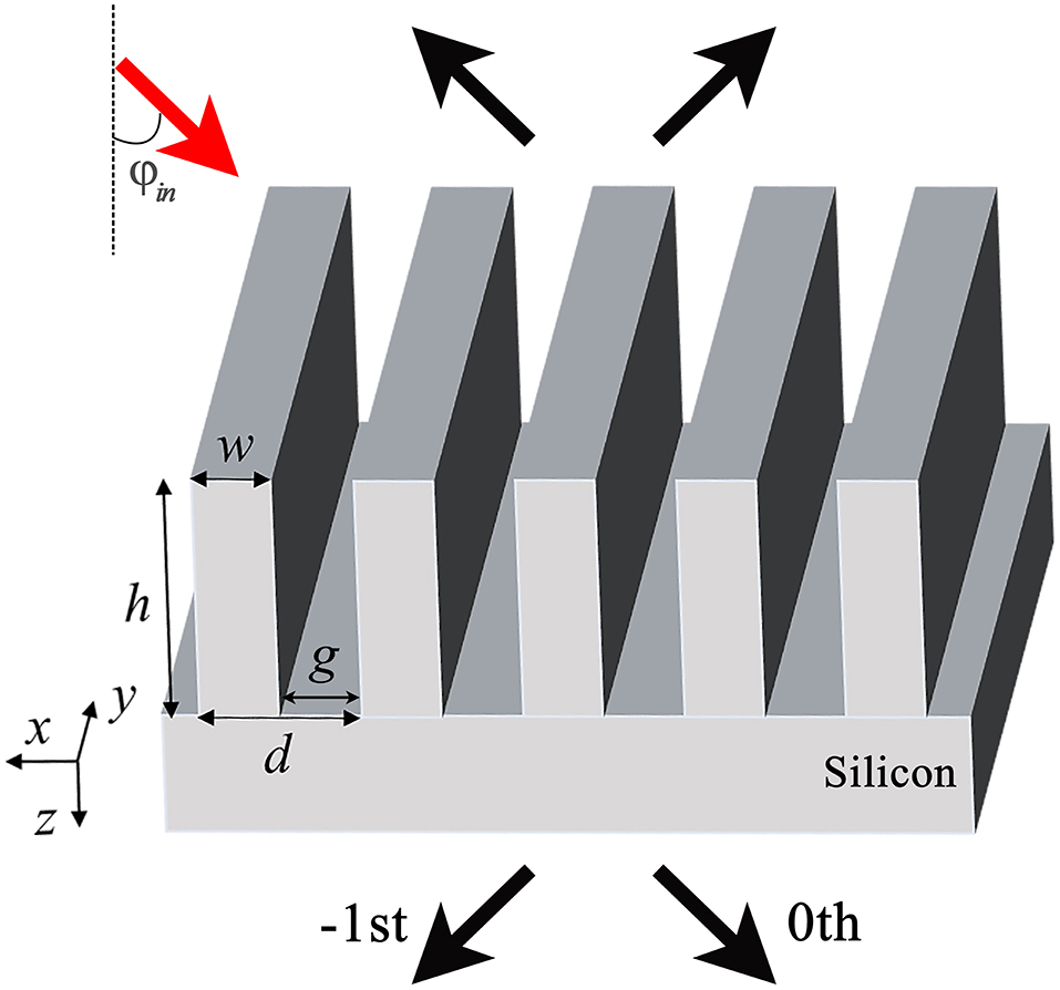
Figure 1. Schematic of the metagrating fabricated on a high-index substrate. The grating and substrate are both made of high-resistivity silicon. The grating parameters are the grating period d, the ridge width w, the groove width g, and the groove depth h.
Here, we restrict the metagrating parameters to the ranges where there are only two propagation modes. In other words, there are only two real solutions of neff,m in Equations (2) and (3) corresponding to propagation modes, and the imaginary solutions correspond to evanescent modes. In the SMM, those evanescent modes are ignored as they contribute little after propagating a certain distance. Because there is a difference between their effective refractive indices, the two propagation modes will accumulate a phase difference after propagation. Hence, the interference between the two propagation modes determines the efficiency of the diffraction orders. Normally, the calculation of interference involves an overlap integral because the energy coupled into the two propagation modes is different. However, when the waves are incident on the grating at the Littrow angle, the first two diffraction orders are symmetric, so as are the two propagation modes in the grating. In this case, the two propagation modes carry the same amount of energy, and the phase difference between the two modes determines the diffraction efficiencies.
The interference process in the grating as previously described is similar to the interference in a Mach-Zehnder interferometer [40]. The analogy is illustrated in Figure 2. In a Mach-Zehnder interferometer, the incident wave is split into two identical waves, and they propagate through two different paths or materials. After interfering with each other, the wave propagates out of the interferometer from port 1 or 2 or both of them. The intensity of the outgoing wave is determined by the optical path difference of the two split waves. Neglecting the reflection at the grating input, the interference within the grating is just like that in the Mach-Zehnder interferometer. The two propagation grating modes have the same propagation length but different effective refractive indices. Thus, the two modes will acquire a phase difference just like the two split beams in the Mach-Zehnder interferometer. The efficiencies of the diffraction orders are likewise determined by the effective optical path difference between the two propagation modes. If the phase difference is zero, starting from a grating depth of zero corresponding to a silicon plate, the diffracted wave leaves the grating from the 0th order. As the grating depth increases, the phase difference increases, so is the efficiency of the −1st diffraction order. The efficiency of the −1st diffraction order achieves maximum when the phase difference reaches π. By this means, the efficiencies of the diffraction orders are given by [40]:
where hmax = λ/(2|neff,1 − neff,2|) is the grating depth when the phase difference reaches π, and t represents the transmission coefficient of the grating.
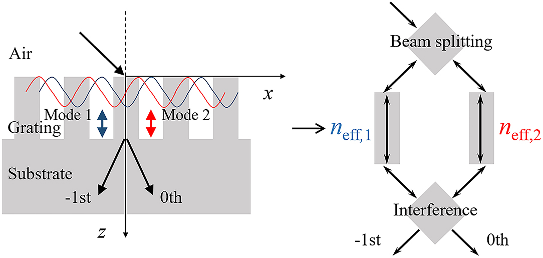
Figure 2. Schematic illustration of two-mode SMM for modeling the grating as a Mach-Zehnder interferometer neglecting the reflection of grating.
When the refractive index of the material is large, as in our case, the reflection should be considered. The reflection at the air/grating interface can be treated as that at two homogeneous media with respective effective refractive indices of and neff,m (m denoting the mode number). The reflection at the grating/substrate interface is treated in the same way. The reflection and transmission coefficients of the mth propagation mode are given by: [41]
where is the effective refractive index in silicon. Multireflection is not taken into account here in order to simplify the calculation. The transmission coefficient is described as
where um(x) is the mode field distribution.
As can be seen from the preceding discussion, the calculation process by the SMM is extremely simple compared with more rigorous numerical methods. A comparison of the results calculated by the SMM and the finite element method (FEM) based on COMSOL Multiphysics is presented in Figure 3. Here the grating parameters are the grating period d = 260 μm and the fill factor f = 0.3. The two materials of the grating are high-resistivity silicon and air, whose refractive indices are 3.45 and 1, respectively. The incident light is illuminated on the grating at an angle of 46°, the Littrow angle. The solid and dashed lines represent the results calculated by the FEM and SMM, respectively. In order to simplify the calculation process, evanescent modes and multireflection are not taken into account, which are known to affect the accuracy of the SMM [42]. The complicated interaction between the grating modes is then reduced to a series of analytic equations. Considering above simplifications made in the SMM, the overall agreement between two methods is good. The SMM produces slightly higher transmissions because the multireflection process within the grating is neglected. The multireflection process together with the ignored evanescent modes can lead to the slight shift of the curves [42]. In short, the SMM can well predict the performance of the grating and greatly simplify the design process and will be used first to yield the grating parameters, which will be improved upon by the FEM.
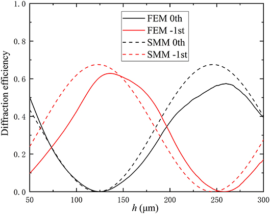
Figure 3. Diffraction efficiency of 0th and −1st orders for TM waves calculated by FEM (solid lines) and SMM (dashed lines), respectively. The grating parameters are d = 260 μm and f = 0.3. The refractive indices of the grating are 3.45 and 1 for silicon and air, respectively. Black and red lines represent 0th and −1st diffraction orders, respectively.
Design of Polarization Beam Splitters
Traditionally, sweeping parameters for a particular grating design is time-consuming. By contrast, the SMM provides a physical vision of the relationship between the grating parameters and its diffraction efficiencies. Given the grating parameters, its diffraction efficiencies can be calculated by very simple equations. On the other hand, by solving the preceding equations reversely, the required grating parameters can also be obtained. Therefore, the reverse grating design could be accomplished very simply. THz metagrating beams splitters will be designed in the following. Based on the working frequency, the period, fill factor, and groove depth of the grating are determined in sequence.
The double-beam-interference approximation in the SMM assumes symmetrical outputs, the 0th and −1st diffraction orders, so that the incident angle needs to satisfy the Littrow condition (ϕin = λ/2d). A large incident angle also causes large reflection, which means that the grating needs a relatively large grating period. However, the grating period needs to be chosen to make sure there are two only two diffraction orders. Therefore, for the 0.8 THz working frequency, the grating period is chosen to be 260 μm to meet the preceding conditions. The corresponding Littrow angle is 46°.
Next, the fill factor and grating depth need to be determined. As previously derived, efficiencies of the TE and TM waves can be described by Equations (4) and (5), from which it can be seen that the peak of the diffraction efficiencies is determined by hmax. When the grating depth h = mhmax with m being an odd number, the −1st order diffraction efficiency achieves maximum. The 0th order diffraction efficiency achieves maximum when the grating depth is h = nhmax with n being an even number. The quantity is related with the difference between the effective refractive indices of the two modes, which can be calculated from the grating Equations (2) and (3). That is to say, the difference between the two effective mode indices determines the diffraction efficiencies. Because the grating equations for TE and TM waves are different, TE and TM waves have different values of hmax. For the THz PBS, the incident TE and TM waves are split into two different diffraction orders (TE waves to the 0th order and TM waves to the −1st order or the opposite). Once the grating period is fixed, the grating depth h needs to meet the condition of h = hmax,TE = 2hmax,TM or h = hmax,TM = 2hmax,TE by changing the fill factor of the grating. At this point, the peak of the 0th order diffraction of the TE wave coincides with that of the −1st order diffraction of the TM wave, or vice versa. Thus, TE and TM waves propagate through different ports. Figure 4 shows how hmax varies with the fill factor for both polarizations when the grating period is fixed at 260 μm. As shown in there, when the fill factor f = 0.23, hmax,TM = 2hmax,TE. If the grating depth h is chosen to be 205 μm, TE and TM waves will propagate through the 0th order and −1st order, respectively, according to our analysis.
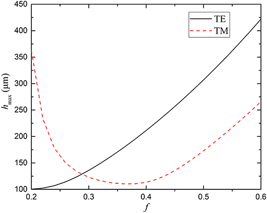
Figure 4. Values of hmax for different fill factors for TE (black line) and TM (red line) modes.
Now that all the grating parameters have been determined, the FEM is used to validate and slightly adjust the parameters. The optimal grating parameters are finally determined to be d = 260 μm, f = 0.23, and h = 210 μm. Figure 5 displays the diffraction efficiencies of the metagrating calculated by COMSOL. Here, the TE wave propagates through the 0th order and the TM wave through the −1st order at 0.8 THz as designed. The diffraction efficiencies of the device are 50% and 70% for TE and TM waves, respectively. The large difference between the refractive indices of silicon and air is the primary reason of the overall low working efficiency. According to the Fresnel equations, the transmittances at an air/silicon interface for a silicon plate are 0.57 and 0.83 for TE and TM waves at an incident angle of 46 degrees, respectively, which means the corresponding conversion efficiencies of the device are 87.7 and 84.3% for TE and TM waves. Here, conversion efficiency is defined as the ratio of the diffraction efficiency of the grating to the transmittance of a single air/silicon interface with no structure. As fabrication error is inevitable, the device designed must have good tolerance of the parameter deviation, especially of the grating depth. Finally, Figure 6 compares the diffraction efficiencies for TE and TM waves by the SMM and FEM. The discrepancy for TE wave is larger due to the fact that the effective refractive indices neff,mfor TE wave have a larger difference from the refractive indices of the substrate and air than those for TM wave do, thus causing larger reflections at the interfaces [40, 42]. Figure 7 also indicates that the diffraction efficiency for the TE wave is more severely affected, but it does not drop significantly for a deviation <10 μm.
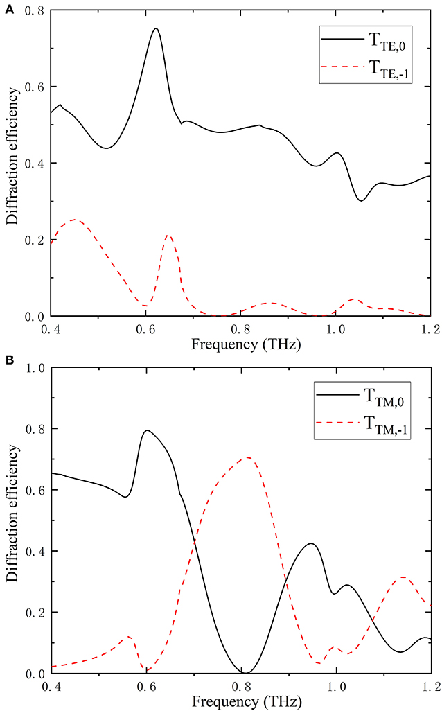
Figure 5. Simulated diffraction efficiency of 0th and −1st orders as a function of frequency for (A) TE and (B) TM waves, respectively. The grating parameters are d = 260 μm, f = 0.23, and h = 210 μm. The incident angle is 46°, the Littrow angle of the grating. Black and red lines represent 0th and −1st diffraction orders, respectively.
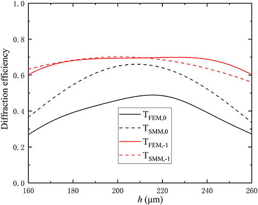
Figure 6. Diffraction efficiency of 0th order for TE wave (black lines) and −1st order for TM wave (red lines) at 0.8 THz as a function of grating depth. Solid and dashed lines represent results calculated by FEM and SMM, respectively.
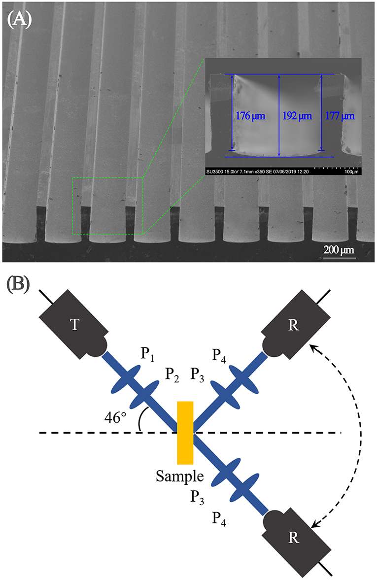
Figure 7. (A) Scanning electron microscopy image of the PBS device. (B) Schematic of the experimental setup. T, R, and P represent the THz transmitter, receiver, and broadband linear polarizers, respectively.
Experimental Results
To further testify our design strategy, a metagrating device is fabricated and experimentally characterized. The air/silicon grating is manufactured by photolithography followed by deep reactive ion etching. A scanning electron microscopy image of the fabricated PBS device is shown in Figure 7A. The diffraction efficiencies of the PBS device are measured on a fiber laser-based THz time-domain spectroscopy system, part of which is illustrated in Figure 7B. In the experiment, the incident angle is set to be 46°. By rotating the angle between the receiver and the sample, the time-domain THz signal is measured, since the THz transmitter and receiver only work for THz waves with horizontal polarization (TM polarization). The conversion between TE and TM waves in the measurement are achieved via two broadband linear polarizers P1 and P2 in the transmission arm, and P3 and P4 in the detection arm by two 45-degree-field-projection processes. In this way, the performance of the PBS device at multi-angles is studied.
The measured time-domain signal is then transformed to the frequency domain by fast Fourier transform for analysis. To further compare the experimental and simulation results, Figure 8 presents the two-dimensional maps of the simulated and measured angle-resolved diffraction efficiencies for TE and TM waves, where the measured grating parameters are used. Both waves are illuminated on the grating device at the Littrow angle of 46°. As Figure 8 demonstrates, the simulation and measurement results are in good agreement. However, the experimental and simulation results show that the working frequency shifts to 0.9 THz from the designed 0.8 THz; the deviation from the design is mainly due to the parameter variations in the fabricated device. The measured grating depth is h = 192 μm, as shown in Figure 7A. The lower grating depth causes a blueshift of the working frequency. Although the design is aimed at a single frequency, the metagrating reveals its diffractive property under broadband THz wave illumination. As shown in Figure 8D, the TM wave is diffracted to the −1st order within a frequency range around 0.9 THz, and the larger the wavelength, the larger the diffraction angle, consistent with the grating equation (1) and the simulation results in Figure 5B. The lower frequencies diffract to angles outside the measurement range. In addition, most of the energy remains in the 0th order and much weaker TE wave is diffracted to the −1st order above 1 THz, as can also be seen from Figure 5A where the diffraction efficiency of the 0th order drops, and the −1st order slightly rises. In agreement with the simulation results in Figure 5, the diffraction into the 0th order for both waves at 0.6 THz is also accidentally stronger than that at the working frequency. It should also be noted that the diffraction efficiencies of the device are lower than design because the reflection at the substrate/air interface is not taken into account in the SMM. The diffraction efficiencies are 69 and 63% for TE and TM waves relative to the transmittances of a silicon plate at an incident angle of 46°, respectively. The simulations and experimental results are closer when the reflection is taken into account. Also, the material loss leads to the reduced transmittance. The material loss might also contribute to the broadening in bandwidth of the measured data in addition to factors of fabrication error and limit in space resolution of the detector. One solution to increasing the diffraction efficiencies is adding an antireflection structure on the substrate/air interface as discussed in our previous work [43]. Also, as the inset in Figure 7A indicates, the inclined walls and uneven bottom of the grating also affect the diffraction efficiencies of the device.
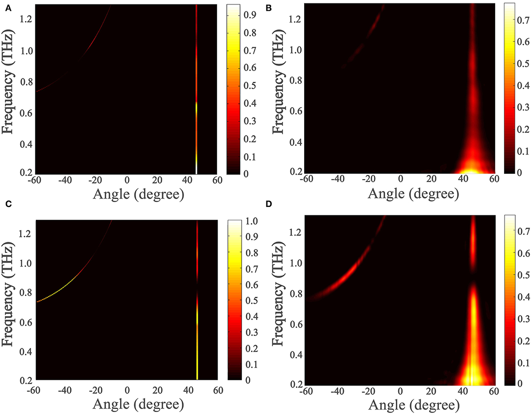
Figure 8. Simulated and experimentally measured grating device efficiencies with frequency and angle. (A) and (C) are simulated efficiencies for TE and TM waves, respectively. (B) and (D) are experimentally measured efficiencies for TE and TM waves, respectively. The grating parameters used in simulation are measured grating parameters: d = 261 μm, f = 0.23, and h = 192 μm.
To further illustrate the function of the device, the far field results at 0.9 THz for TE and TM waves are shown in Figure 9. Because of the blueshift of the working frequency caused by fabrication error, the angle of the −1st diffraction order shifts from −46 to −34°, which makes the light going out of the metagrating asymmetric. But the functionality of the metagrating is not affected, and the extinction ratios are measured to be 12 and 33 dB for TE and TM waves, respectively.
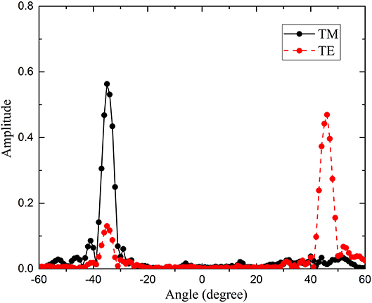
Figure 9. Experimentally measured normalized amplitude vs. measurement angle at 0.9 THz. Black solid and red dashed lines represent TM and TE waves, respectively.
Conclusion
A two-mode SMM is used to design a metagrating-based PBS for THz waves. The THz PBS is fabricated and characterized with a time-domain spectroscopy system. The diffraction efficiencies of the PBS are 69 and 63% for TE and TM waves relative to that of a silicon plate, respectively, and the corresponding extinction ratios are 12 and 33 dB for TE and TM waves. The experimental results agree well with simulations. The simplified model greatly facilitates the grating design procedure and is expected to find use in other similar design scenarios.
Data Availability Statement
All datasets presented in this study are included in the article/supplementary material.
Author Contributions
XM performed the research and wrote the paper. YLi and WZ proposed the concept. YLu and XZ fabricated the sample. JH and XZ supervised the project. All authors contributed to the revision of the article and approved the submitted version.
Funding
This work was supported by the National Key Research and Development Program of China (Grant No. 2017YFA0701004), the National Natural Science Foundation of China (Grant Nos. 61775159, 61420106006, 61427814, 61422509, 61735012, and 61505146), the Tianjin Municipal Fund for Distinguished Young Scholars (Grant No. 18JCJQJC45600), and King Abdullah University of Science and Technology (KAUST) Office of Sponsored Research (OSR) (Grant No. OSR-2016-CRG5-2950).
Conflict of Interest
The authors declare that the research was conducted in the absence of any commercial or financial relationships that could be construed as a potential conflict of interest.
Acknowledgments
The authors are grateful to Fan Yang of Tsinghua University for valuable discussions.
References
1. Kleine-Ostmann T, Nagatsuma T. A review on terahertz communications research. J. Infrared Millimeter Terahertz Waves. (2011) 32:143–71. doi: 10.1007/s10762-010-9758-1
2. Federici JF, Moeller L. Review of terahertz and subterahertz wireless communications. J. Appl. Phys. (2010) 107:111101. doi: 10.1063/1.3386413
3. Nagatsuma T, Ducournau G, Renaud C. Advances in terahertz communications accelerated by photonics. Nat. Photon. (2016) 10:371–79. doi: 10.1038/nphoton.2016.65
4. Appleby R, Wallace HB. Standoff detection of weapons and contraband in the 100 GHz to 1 THz region. IEEE Trans. Antennas Propag. (2007) 55 2944–56. doi: 10.1109/TAP.2007.908543
5. Tonouchi M. Cutting-edge terahertz technology. Nat. Photon. (2007) 1:97–105. doi: 10.1038/nphoton.2007.3
6. Zeitler JA, Gladden LF. In-vitro tomography and non-destructive imaging at depth of pharmaceutical solid dosage forms. Eur. J. Pharm. Biopharm. (2009) 71:2–22. doi: 10.1016/j.ejpb.2008.08.012
7. Kampfrath T, Tanaka K, Nelson KA. Resonant and nonresonant control over matter and light by intense terahertz transients. Nat. Photon. (2013) 7:680–90. doi: 10.1038/nphoton.2013.184
8. Dhillon S, Vitiello M, Linfield E, Davies A, Hoffmann M, Booske J, et al. The 2017 terahertz science and technology roadmap. J. Phys. D Appl. Phys. (2017) 50:043001. doi: 10.1088/1361-6463/50/4/043001
9. Caldwell JD, Lindsay L, Giannini V, et al. Low-loss, infrared and terahertz nanophotonics using surface phonon polaritons. Nanophotonics. (2015) 4:44–68. doi: 10.1515/nanoph-2014-0003
10. Mittleman DM. Twenty years of terahertz imaging. Opt. Express. (2018) 26:9417–31. doi: 10.1364/OE.26.009417
11. Ako RT, Upadhyay A, Withayachumnankul W, et al. Dielectrics for terahertz metasurfaces: material selection and fabrication techniques. Adv. Opt. Mater. (2020) 8:1900750. doi: 10.1002/adom.201900750
12. Smith DR, Padilla WJ, Vier DC, Nemat-Nasser SC, Schultz S. Composite medium with simultaneously negative permeability and permittivity. Phys. Rev. Lett. (2000) 84:4184–87. doi: 10.1103/PhysRevLett.84.4184
13. Landy NI, Sajuyigbe S, Mock J, Smith DR, Padilla WJ. Perfect metamaterial absorber. Phys. Rev. Lett. (2008) 100:207402. doi: 10.1103/PhysRevLett.100.207402
14. Li W, Valentine J. Metamaterial perfect absorber based hot electron photodetection. Nano Lett. (2014) 14:3510–14. doi: 10.1021/nl501090w
15. Schurig D, Mock J, Justice BJ, Cummer SA, Pendry JB, Starr AF, et al. Metamaterial electromagnetic cloak at microwave frequencies. Science. (2006) 314:977–80. doi: 10.1126/science.1133628
16. Pfeiffer C, Zhang C, Ray V, Guo JL, Grbic A. High performance bianisotropic metasurfaces: asymmetric transmission of light. Phys. Rev. Lett. (2014) 113:023902. doi: 10.1103/PhysRevLett.113.023902
17. Zheng G, Mühlenbernd Holger, Kenney M, Li G, Zentgraf T, Zhang S. Metasurface holograms reaching 80% efficiency. Nat. Nanotechnol. (2015) 10:308–12. doi: 10.1038/nnano.2015.2
18. Ni X, Kildishev A, Shalaev V. Metasurface holograms for visible light. Nat. Commun. (2013) 4:2807. doi: 10.1038/ncomms3807
19. Zi J, Xu Q, Wang Q, Tian C, Li Y, Zhang X, et al. Antireflection-assisted all-dielectric terahertz metamaterial polarization converter. Appl. Phys. Lett. (2018) 113:101104. doi: 10.1063/1.5042784
20. Chen X, Tian Z, Lu Y, Xu Y, Zhang X, Ouyang C, et al. Electrically tunable perfect terahertz absorber based on a graphene Salisbury screen hybrid metasurface. Adv. Opt. Mater. (2020) 8:1900660. doi: 10.1002/adom.201900660
21. Dong D, Liu Y, Fei Y, Fan Y, Li J, Fu Y. Polarization beam splitter based on extremely anisotropic black phosphorus ribbons. Opt. Express. (2020) 28:8371–83. doi: 10.1364/OE.388845
22. Ung BS, Fumeaux C, Lin H, Fischer BM, Ng BW, Abbott D. Low-cost ultra-thin broadband terahertz beam-splitter. Opt. Express. (2012) 20:4968–78. doi: 10.1364/OE.20.004968
23. Lee WS, Nirantar S, Headland D, Bhaskaran M, Sriram S, Fumeaux C, et al. Broadband terahertz circular-polarization beam splitter. Adv. Opt. Mater. (2018) 6:1700852. doi: 10.1002/adom.201700852
24. Wei M, Xu Q, Wang Q, Zhang X, Li Y, Gu J, et al. Broadband non-polarizing terahertz beam splitters with variable split ratio. Appl. Phys. Lett. (2017) 111:071101. doi: 10.1063/1.4986538
25. Zang X, Gong H, Li Z, Xie J, Cheng Q, Chen L, et al. Metasurface for multi-channel terahertz beam splitters and polarization rotators. Appl. Phys. Lett. (2018) 112:171111. doi: 10.1063/1.5028401
26. Xing X, Li Y, Lu Y, Zhang W, Zhang X, Han J, et al. Terahertz metamaterial beam splitters based on untraditional coding scheme. Opt. Express. (2019) 27:1627–35. doi: 10.1364/OE.27.0A1627
27. Chang-Hasnain CJ, Yang W. High-contrast gratings for integrated optoelectronics. Adv. Opt. Photon. (2012) 4:379–440. doi: 10.1364/AOP.4.000379
28. Popov V, Boust F, Burokur SN. Controlling diffraction patterns with metagratings. Phys. Rev. Appl. (2018) 10:011002. doi: 10.1103/PhysRevApplied.10.011002
29. Epstein A, Rabinovich O. Unveiling the properties of metagratings via a detailed analytical model for synthesis and analysis. Phys. Rev. Appl. (2017) 8:054037. doi: 10.1103/PhysRevApplied.8.054037
30. Sell D, Yang J, Wang EW, Phan T, Doshay S, Fan J. Ultra-high-efficiency anomalous refraction with dielectric metasurfaces. ACS Photon. (2018) 5:2402–07. doi: 10.1021/acsphotonics.8b00183
31. Radi Y, Alu A. Reconfigurable metagratings. ACS Photon. (2018) 5:1779–85. doi: 10.1021/acsphotonics.7b01528
32. Deng Z, Deng J, Zhuang X, Wang S, Shi T, Wang G, et al. Facile metagrating holograms with broadband and extreme angle tolerance. Light Sci. Appl. (2018) 7:78. doi: 10.1038/s41377-018-0075-0
33. Zhu J, Jiang S, Xie Y, Li F, Du L, Meng K, et al. Enhancing terahertz molecular fingerprint detection by a dielectric metagrating. Opt. Lett. (2020) 45:2335–38. doi: 10.1364/OL.389045
34. Moharam MG, Gaylord TK. Diffraction analysis of dielectric surface-relief gratings. J. Opt. Soc. Am. (1982) 72:1385–91. doi: 10.1364/JOSA.72.001385
35. Collin RE. Reflection and transmission at a slotted dielectric interface. Can. J. Phys. (1956) 34:398–411. doi: 10.1139/p56-047
36. Botten IC, Craig MS, McPhedran RC, Adams JL, Andrewartha JR. The dielectric lamellar diffraction grating. Opt. Acta. (1981) 28:413–28. doi: 10.1080/713820571
37. Clausnitzer T, Kämpfe T, Kley E, Tünnermann A. An intelligible explanation of highly-efficient diffraction in deep dielectric rectangular transmission gratings. Opt. Express. (2005) 13:10448–456. doi: 10.1364/OPEX.13.010448
38. Foresti M, Menez L, Tishchenko A V. Modal method in deep metal-dielectric gratings: the decisive role of hidden modes. J. Opt. Soc. Am. A. (2006) 23:2501–09. doi: 10.1364/JOSAA.23.002501
39. Clausnitzer T, Kaempfe T, Kley EB, Tünnermann A, Tishchenko A, Parriaux O. Investigation of the polarization-dependent diffraction of deep dielectric rectangular transmission gratings illuminated in Littrow mounting. Appl. Opt. (2007) 46:819–26. doi: 10.1364/AO.46.000819
40. Clausnitzer T, Kämpfe T, Kley E, Tünnermann A, Tishchenko A, Parriaux O. Highly-dispersive dielectric transmission gratings with 100% diffraction efficiency. Opt. Express. (2008) 16:5577–84. doi: 10.1364/OE.16.005577
41. Sun W, Lv P, Zhou C, Cao H, Wu J. Multireflection modal method for wideband fused-silica transmission gratings. Appl. Opt. (2013) 52:2800–07. doi: 10.1364/AO.52.002800
42. Yang F, Li Y. Evaluation and improvement of simplified modal method for designing dielectric gratings. Opt. Express. (2015) 23:31342–356. doi: 10.1364/OE.23.031342
Keywords: metagrating, metamaterial, polarization beam splitter, simplified modal method, terahertz wave
Citation: Ma X, Li Y, Lu Y, Han J, Zhang X and Zhang W (2020) Metagrating-Based Terahertz Polarization Beam Splitter Designed by Simplified Modal Method. Front. Phys. 8:580781. doi: 10.3389/fphy.2020.580781
Received: 07 July 2020; Accepted: 02 September 2020;
Published: 15 October 2020.
Edited by:
Longqing Cong, University of Pennsylvania, United StatesReviewed by:
Fei Fan, Nankai University, ChinaSong Han, Nanyang Technological University, Singapore
Copyright © 2020 Ma, Li, Lu, Han, Zhang and Zhang. This is an open-access article distributed under the terms of the Creative Commons Attribution License (CC BY). The use, distribution or reproduction in other forums is permitted, provided the original author(s) and the copyright owner(s) are credited and that the original publication in this journal is cited, in accordance with accepted academic practice. No use, distribution or reproduction is permitted which does not comply with these terms.
*Correspondence: Yanfeng Li, eWFuZmVuZ2xpQHRqdS5lZHUuY24=