 Yanfang Huang1
 Yimin Shao2Yang Bai2Qingchun Yuan3
 Tingzhen Ming4Philip Davies5
 Xiaohua Lu6
 Renaud de Richter7
 Wei Li2*
- 1Department of Chemical and Biological Engineering, Nantong Vocational University, Nantong, China
- 2Institute for Materials and Processes, School of Engineering, The University of Edinburgh, Edinburgh, United Kingdom
- 3School of Engineering and Applied Science, Aston University, Birmingham, United Kingdom
- 4School of Civil Engineering and Architecture, Wuhan University of Technology, Wuhan, China
- 5School of Engineering, University of Birmingham, Birmingham, United Kingdom
- 6State Key Laboratory of Materials-Oriented Chemical Engineering, College of Chemical Engineering, Nanjing Tech University, Nanjing, China
- 7Tour-Solaire.fr, Montpellier, France
Due to the alarming speed of global warming, greenhouse gas removal from atmosphere will be absolutely necessary in the coming decades. Methane is the second most harmful greenhouse gas in the atmosphere. There is an emerging technology proposed to incorporating photocatalysis with solar updraft Towers (SUT) to remove methane from the air at a planetary scale. In this study, we present a deep analysis by calculating the potential of methane removal in relation to the dimensions and configuration of SUT using different photocatalysts. The analysis shows that the methane removal rate increases with the SUT dimensions and can be enhanced by changing the configuration design. More importantly, the low methane removal rate on conventional TiO2 photocatalyst can be significantly improved to, for example, 42.5% on a more effective Ag-doped ZnO photocatalyst in a 200 MW SUT while the photocatalytic reaction is the rate limiting step. The factors that may further affect the removal of methane, such as more efficient photocatalysts, night operation and reaction zone are discussed as possible solutions to further improve the system.
Introduction
One of the grand challenges humankind is facing is global warming. The 2018 report of Intergovernmental Panel on Climate Change (IPCC) emphasizes the need for “rapid and far-reaching” actions now to curb carbon emission to limit global warming and climate change impact (Masson-Delmotte et al., 2018). Countries all around the globe are setting up ambitious target to reach carbon neutrality.
Several anthropogenic emissions which are extremely difficult to eliminate (i.e. from aviation or from agriculture) will need to be balanced by negative emission technologies (NETs) to achieve overall neutrality.
On the one hand, the NETs proposed until today are mainly based on carbon dioxide removal (CDR), but require safe and reliable sequestration of billions of tons of CO2, including capture, purification, compression and transportation to the storage sites (Kuramochi et al., 2012; Leung et al., 2014; Wetenhall et al., 2014; Kolster et al., 2017).
On the other hand, few greenhouse gas (GHG) removal methods of the other GHGs (methane CH4, nitrous oxide N2O, and ozone layer depleting gases included in the Montreal protocol like hydrochlorofluorocarbons, hydrofluorocarbons and chlorofluorocarbons) have yet been proposed, but have the advantage that these GHGs can be transformed or destroyed into benign gases and consequently don’t require sequestration and storage (United States Environmental Protection Agency (US EPA), 2013; Sikkema and dissertation, 2013; Jackson et al., 2019).
Moreover, the Global Warming Potential (GWP) of many of the non-CO2-GHGs are much higher than that of CO2. For example, the GWP of methane is nearly 28 times higher than that of CO2 on a 100-years basis, and 84 times higher on a 20-years basis (Masson-Delmotte et al., 2018).
In the atmosphere, the main processes by which the majority of non-CO2-GHGs are destroyed or transformed into benign gases are 1) hydroxyl radical oxidation, 2) photolysis and 3) reaction with halogen atoms. Photocatalytic processes (reactions activated by photons and accelerated by catalysts), have been shown to be able to transform almost all GHGs into benign gases (de Richter and Caillol, 2011) and even to reduce and transform CO2 to fuels or useful chemicals (Brudvig and Campagna, 2017; Hisatomi and Domen, 2017).
Many efficient photocatalytic materials have been explored in recent years (Liu et al., 2019; Sekar et al., 2019; Aljaafari et al., 2020; Qi et al., 2020a; Qi et al., 2020b; Qi et al., 2020c; Qi et al., 2020d; Jiang et al., 2020; Wang et al., 2020; Zada et al., 2020; Li et al., 2021; Sekar et al., 2021; Zhang et al., 2021; Zhou et al., 2021). Several of them are very efficient for the total oxidation of methane, including several TiO2 modified derivatives and other metal oxides (Jin et al., 2017). Chen et al. demonstrated a cheap ZnO derivative doped with 0.1% silver that efficiently oxidize methane under ambient conditions with high stability in this particular gas phase application (Chen et al., 2016). Minami et al. studied the oxidation of methane by TiO2 (Minami and Kim, 2006). They concluded that, within the concentration range studied, the decomposition reactions were first-order, with activation energy of 16.6 kJ/mol for methane, derived from the overall reaction rate constant. Krishna et al. reported another photocatalyst (i.e. uranyl-anchored MCM-41) and showed high activity for the total oxidation of methane under sunlight at ambient conditions (Krishna et al., 2004). Foam-nickel coated by TiO2 can photocatalytically oxidize air pollutants and can be applied to various household systems for heating, ventilation and air-conditioning, designed by Yang et al. (2009). Some other researchers like Kleinschmidt, Haeger et al., provided more insights into the kinetic of the oxidation reactions from methane to fully oxidized CO2 (Kleinschmidt and Hesse, 2002; Haeger et al., 2004a; Haeger et al., 2004b).
The above photocatalysts for methane oxidation were only tested in very small lab scale. In order to reduce significantly the atmospheric concentration of CH4, it is necessary to process significant volumes of air at planetary scale. In a previous report (de Richter et al., 2017), the authors, for the first time, proposed to use solar updraft towers (SUTs) for this purpose, which consist of a large glazed solar greenhouse supplying warm air to a tall chimney where the airflow is induced by the stack effect (Haaf et al., 1983; Haaf, 1984; Cao et al., 2015; Liu et al., 2021; Ming et al., 2021). By coating the glazed canopy and the ground of the greenhouse by a photocatalyst, the SUT may be modified as a giant photocatalytic reactor, as shown in Figure 1.
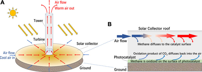
FIGURE 1. (A) The structure of SUT, (B) a conceptual diagram of the integrated system for methane removal through SUT.
Using the above lab scale data to analyze the performance of photocatalysis in giant SUTs is the essential first step to understand the feasibility of this proposed NET. A preliminary analysis based on heat transfer models indicated that it would remove 2 out of 3 CH4 molecules entering (de Richter et al., 2017). This was based on experimental data collected from the biggest SUT prototype ever built, by extrapolation of measured heat transfer data to estimate the potential effectiveness of mass transfer if the device is used as photocatalytic reactors.
A more comprehensive and reliable analysis is much needed. Besides mass transfer via the boundary layers between the bulk flow and the surface of the catalyst, several other factors would in practice limit the effectiveness of the process, local adsorption, surface reaction, desorption kinetics, quantum yield, etc.
By deeper analysis of the main relevant processes, this study, for the first time, presents such a comprehensive and reliable analysis of the effectiveness of SUT enabled photocatalysis for methane removal at planetary scale.
Theory
Photocatalytic degradation of atmospheric methane is a heterogeneous catalytic reaction, which happens at the interface between air and photocatalyst when methane flows through the surface of photocatalyst with air. The mechanism diagram of the reaction is shown in Figure 2 and the process can be generally divided into the following six steps:
1) Diffusion of methane to the surface of Photocatalyst;
2) Adsorption of methane on the surface of photocatalyst;
3) Hole-photon pair excited by light irradiation;
4) Methane molecules react on the surface of photocatalyst to produce products;
5) Desorption of products from the surface of photocatalyst;
6) Diffusion of products from the surface of photocatalyst to bulk gas.
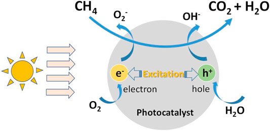
FIGURE 2. The mechanism diagram of photocatalytic oxidation of methane.
There are both physical changes and chemical reactions in the above six steps, among which 1) and 6) are convection/diffusion processes, 2) and 5) are adsorption and desorption on the surface, 3) are photon excitation processes, and 4) are surface photocatalytic reaction. 2), 4) and 5) are regarded as three basic steps of heterogeneous catalysis. It is worth noting that the conversion of CO2 and H2O to CH4 is not observable in this process because it is largely an oxidation atmosphere rather than reduction atmosphere in ambient conditions.
In order to effectively apply SUT to methane mitigation in the air, an understanding of the relevant mass transfer and kinetic phenomena is required.
Results and Discussion
How Much CH4 Flow Through SUT?
The analyses are based on the experimental results of the SUT in Spain collected in 1982 (Haaf et al., 1983; Haaf, 1984). The key dimensions and data of the Spanish prototype are shown in Table 1.
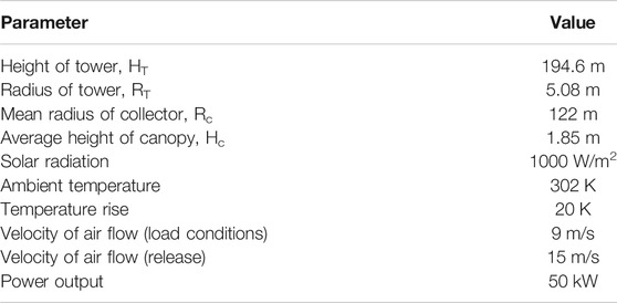
TABLE 1. Key dimensions and data of the Spanish pilot plant.
There are two different places to coat photocatalyst, on the ground or on the surface under the canopy. In the following analysis, we assume that the photocatalyst is coated on the ground surface. Air is supplied to the chimney from the entrance of the collector similar to a greenhouse along the radial direction. In this process, it contacts the photocatalyst coated on the ground and the methane is degraded. Based on the data in Table 1, it is estimated that the amount of air flowing through the collector is 729 m3/s. If the concentration of methane in the atmosphere is 1.8 ppm, it means nearly 74.5 kg of methane per day and 761 Tonnes of CO2 equivalent per year flowing through this SUT.
Furthermore, if photocatalysis is combined with an up-scaled SUT of 200 MW (i.e. Rc = 3,500 m, HT = 1,000 m and RT = 65 m), it can provide 38 km2 GH area. According to Schlaich et al.’s report (Schlaich et al., 2005), despite the considerable dimensional differences between a 200 MW SUT and the Spanish 50 kW SUT, the main thermodynamic parameters are similar in both cases. Therefore, it is reasonable to assume that the 200 MW SUT has the same temperature rise and tower outlet velocity as the Spanish SUT. The amount of air passing through the collector can be calculated as 2 × 10⁵ m3/s. The amount of methane is 2.0 × 10⁴ kg per day, and nearly 2.1 × 10⁵ Tonnes of CO2 equivalent per year flowing through a single SUT.
Kinetics of Methane Oxidation
In order to simplify the problem, there are two assumptions: 1) only methane reacts on the surface, and there is no multi-component competitive reaction; 2) the reaction is uniform along the radial direction at the same R (R is the distance from the collector center).
Many researchers have described the adsorption and photocatalytic reaction step for CH4 total oxidation. The following analysis is based on data form Haeger et al. (2004a) and Chen et al. (2016).
In Haeger et al.’s report (Haeger et al., 2004b), the kinetics of the total oxidation of methane were studied in a continuous-stirred tank reactor with titanium dioxide as the photocatalyst. The model established by Andreas Haeger et al. can be expressed as,
The parameter values in the above model are as follows:
where, rAI is the reaction rates per absorbed irradiation intensity and geometric surface area of the active plate, mol·W−1 s−1. The product of rAI and light intensity I is the reaction rate r(CH4), mol·m−2 s−1; C(CH4)and C(O2) are the concentration of CH4 and O2 respectively, mol/m3. Plotting C(CH4)/rAI vs. C(CH4), a straight line is achieved (Figure 3).
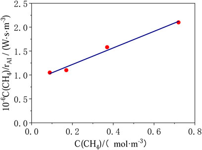
FIGURE 3. Results of photocatalytic total oxidation of methane for oxygen rich mixtures (T = 313 K, p = 1 bar, I = 14.5 W/m2, C(O2) = 6.81 mol/m3).
If the zenith solar intensity is 1120 W/m2, the intensity of light with wavelength less than 400 nm can be estimated to be 56 W/m2 according to the solar spectrum at sea level. Eq. 1 is used to predict initial reaction rate of 4.8 × 10⁻⁹ mol m−2 s−1 at atmospheric methane concentration of 1.8 ppm.
For the 50 kW SUT in Spain, the ground under collector provides 46735 m2 reaction area. It means that 2.2 × 10⁻⁴ mol/s of methane can be removed (i.e. 0.31 kg/day), which is far less than the amount of methane flowing through the collector at nearly 74.5 k/day (i.e. 0.4% of removal rate).
If photocatalysis is combined with 200 MW SUT, the methane removal capacity is 0.18 mol/s, that is, 252 kg/day of methane removal, which is also less than the amount of methane flowing through the collector at 2.0 × 10⁴ kg/day (i.e. 1.3% of removal rate).
Fortunately, beside the less effective TiO2 photocatalyst, there are recent progress on much more effective new photocatalysts for methane oxidation. For example, in Chen et al.’s report (Chen et al., 2016), the photocatalytic methane oxidation over ZnO doped with 0.1 wt% Ag (noted as 0.1-Ag-ZnO) follow pseudo-first-order kinetics. A fitting equation can be obtained by plotting k (the rate constant) with C0 (the initial methane concentration) (Figure 4). The rate constant k and the initial reaction rate can be predicted to be 1.69 min−1 and 3.04 ppm/min at atmospheric methane concentration of 1.8 ppm. Considering the area of the reaction surface (a 7 cm diameter disc) and the volume of reactor (a 0.45 L cylinder vessel), it is estimated that the reaction constant k and initial reaction rate are 0.0035 m/s and 2.36 × 10⁻⁷ mol m−2 s−1, respectively.
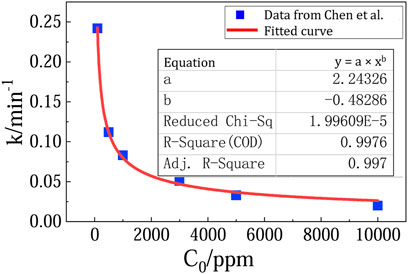
FIGURE 4. Fitting curve of C0 and k from experimental data.
Calculations of methane removal rate based on 0.1-Ag-ZnO photocatalysts is summarized in Table 2 and compared with those based on TiO2. In the 50 kW SUT, methane can be removed at a rate of 15.2 kg/day (i.e. 20% of removal rate). And in a 200 MW SUT, methane can be removed at a rate of 1.24 × 10⁴ kg/day (i.e. 62% of removal rate).
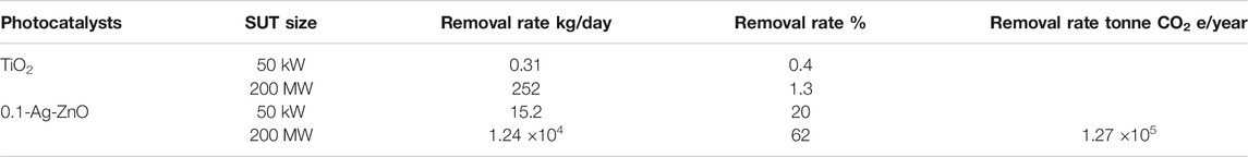
TABLE 2. Methane removal in different sizes of SUT using different photocatalysts.
Mass Transfer
Because of the concentration gradient of methane between bulk fluid and photocatalyst surface, there is a mass transfer flux which are controlled by advection and diffusion (Fogler, 2016). For the present case, the direction of air flow is radial and parallel to the ground, so the mass transfer caused by bulk fluid motion does not need to be considered. The molar diffusive flux of methane can be written as following equation:
where C(CH4) is the averaged methane concentration, mol/m3; Cs(CH4) is the methane concentration in the air next to the air–photocatalyst interface, mol/m3; hm is the mass transfer coefficient, m/s.
Because heat transfer and mass transfer are analogous, correlations for Nusselt and Sherwood numbers are also analogous. Therefore, when the correlation for Nusselt number (Nu), Prandlt number (Pr) and heat transfer coefficient (α) is found based on the data from experiments, the correlation for Sherwood number (Sh), Schmidt number (Sc) and mass transfer coefficient (hm) can be obtained by simple replacement. If the Pr equals Sc, then Nu equals Sh.
For 50 kW SUT, based on the temperature rise, the heat transfer rate is 24,300 kW (de Richter et al., 2017), heat transfer coefficient can be calculated as below
where Q is the heat transfer rate, kW; A is the heat transfer area, m2; and ΔT is the logarithmic mean temperature, K.
Tg is the temperature of the ground, Tair,in is the inlet temperature and Tair,out is the outlet temperature of the collector respectively. Nu number can be calculated by
where Lchar is the characteristic length, m, Lchar = 2Hc. λ is air thermal conductivity, W·m−1K−1. According to the definition of Sh, Eq. 7 can be used to calculate the mass transfer coefficient hm.
where DCH4, air is the diffusion coefficient, m2/s.
If the concentration of methane on the surface of photocatalyst is assumed to be zero and the concentration of methane in the bulk air is kept at 1.8 ppm, the average rate of mass transfer is 1.1 × 10⁻⁶ mol m−2 s−1 calculated from Eq. 3. The main parameters and calculation results are summarized in Table 3.
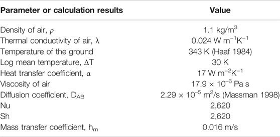
TABLE 3. The key parameters and calculation results.
Sherwood (Sh) number correlations can also be expressed by Sh = constant × Rem× Scn, where Re is Reynolds number. Since the air flowing under the collector is turbulent, according to the literature (Zukauskas and Slanciauskas, 1987), we use the equation Sh = 0,032 × Re0.8× Sc0.43 to calculate Sh.
Table 4 shows the velocity Vc, Re, Sh, and the corresponding mass transfer coefficients at different positions under the collector of a 50 kW SUT system, which can be used for qualitative analysis of mass transfer under collector. It can be seen that at the entrance to the collector, the air velocity is the lowest and the corresponding mass transfer rate constant is the smallest. As the air flows to the center of the collector, the velocity increases and mass transfer coefficient also increases. It is because the higher velocity enhances the air turbulence, which helps to enhance the mass transfer of methane in the air, so the mass transfer coefficient increases. The mass transfer coefficient ranges from 0.0019 to 0.0191 m/s, which is in accordance with the previous results calculated by Reynolds analogy. The mass transfer rates at different positions of the collector can be estimated according to Eq. 3 and list in Table 4.
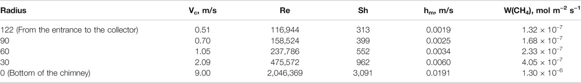
TABLE 4. Key parameters at different positions under the collector for 50 kW SUT.
In the same way, Re, Sh, hm, W(CH4) of 200 MW SUT can be calculated easily, and listed in Table 5. Compared with 50 kW SUT, 200 MW SUT has higher air velocity and mass transfer rate.
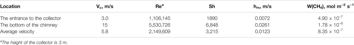
TABLE 5. Key parameters for 200 MW SUT.
To evaluate the mass transfer process comprehensively, it is essential to calculate the average mass transfer coefficient. Because there is not enough data of heat transfer to obtain the average mass transfer rate coefficient by Reynolds analogy method, the average mass transfer rate coefficient is obtained by calculating the average flow rate. The velocity of the air under the collector can be written as following equation:
where t is the residence time, min;
From Eq. 8, it can be estimated that the residence time of air under the collector is 10 min for 200 MW SUT. The average velocity is obtained by dividing the collector radius by the residence time. The mass transfer rate coefficient obtained from the average velocity is shown in Table 5.
Analysis of Rate Limiting Step
By comparing the mass transfer rate W(CH4) with the reaction rate r(CH4), we can determine the rate-limiting step. 1) if W(CH4) >> r(CH4), reaction is the bottleneck of the whole process; 2) if W(CH4) << r(CH4), mass transfer is rate-limiting step, 3) if W(CH4) and r(CH4) are very close, it means that the reaction and mass transfer have equivalent influence and jointly control the whole process.
According to photocatalytic data from TiO2, the photocatalytic decomposition rate of methane is 4.8 × 10⁻⁹ mol m−2 s−1. No matter for 50 kW SUT or 200 MW SUT, even the minimum W(CH4) at the collector entrance is much greater than r(CH4), so photocatalytic reaction is the rate-limiting step.
The reaction rate based on 0.1-Ag-ZnO is 2.16 × 10⁻⁷ mol m−2 s−1, which is close to the diffusion rate. Therefore, for 50 kW SUT, catalytic reaction is the rate-limiting step in the area near the collector inlet, while diffusion is the rate-limiting step in the centre of the collector. For 200 MW SUT, photocatalytic reaction is the rate-limiting step under the whole collector.
Estimation of
According to Eq. 1, the apparent reaction rate constant Kapp can be estimated by the following equation for Haeger et al.’s model (Haeger et al., 2004a).
The mass conservation equation together with the boundary conditions can be written as
where Rcoll is the radius of the collector; Cin(CH4) is the inlet methane concentration; Kapp is the rate constant of apparent reaction, m/s.
The solution to Eq. 10 is
where Ar is the surface area of reaction, m2. Cout(CH4) is the methane concentration in the outlet air. The methane removal effectiveness of a SUT can be characterized by the fractional conversion.
If methane is completely decomposed,
The number of mass transfer units (NTUm) is defined as,
Equation 16 is often used to assess the number of mass transfer units in a process that contains both physical mass transfer and chemical reaction.
The calculation results of NTUm and ε are shown in Table 6. If the photocatalytic technology is applied to 50 kW SUT, the methane removal rates are 0.44 and 17.5% with TiO2 and 0.1-Ag-ZnO respectively, which are lower than the results previously analysed (de Richter et al., 2017) and the methane removal rates calculated in Table 2. The main reason is that the previously analysed results only consider the mass transfer process, while the removal rate in Table 2 only considers the photocatalytic reaction kinetics. But in fact, the whole process involves both photocatalytic reaction and mass transfer process. The methane removal rates in a 200 MW SUT are 1.4 and 42.5% with TiO2 and 0.1-Ag-ZnO respectively.
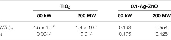
TABLE 6. NTUm and
Further Discussion
Photocatalysts
With the understanding of relevant mass transfer and kinetic phenomena, it is found that the overall rate of methane oxidation is limited by the adsorption and oxidation step rather than the diffusion of the species to the surface in most scenarios. Therefore, the future efforts should focus on improvement of photocatalytic materials.
The above analysis is based on two typical photocatalysts for methane oxidation, i.e. less effective TiO2 and more effective 0.1-Ag-ZnO sample. It is found that the process is almost unfeasible due to the relatively low methane removal rate on TiO2. However, for 200 MW SUT, the methane removal rate can reach 42.5% if 0.1-Ag-ZnO is used. Figure 5 shows the methane removal rates can be further enhanced if even higher reaction rates can be achieved by developing even more advanced photocatalysts. For example, if the reaction rate reaches 1 × 10⁻⁵ mol m−2 s−1, the methane removal rate of 200 MW SUT can reach 73%. The development of photocatalysts with high reaction rate is undoubtedly the primary task.
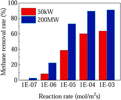
FIGURE 5. Methane removal rate at different reaction rates.
Catalyst Loading Amount (i.e. Coating Area)
In addition to types of photocatalysts, we can also take some other strategies to improve the photocatalytic reaction rate, such as increasing the loading amount (i.e. reaction area). There are different ways to apply photocatalysts, e.g. on the surface under the canopy, or on the ground or both. Multi-layer roof is another method that can effectively increase the reaction area (Pretorius, 2007; de Richter et al., 2016), as shown in Figure 6. It should be pointed out that although the multi-layer roofs can effectively increase the reaction area, if too many layers are needed for sufficient contact area, perhaps poorer mass transfer would occur due to slower air flow and thicker boundary layers. The intensity of sunlight will also be weakened.
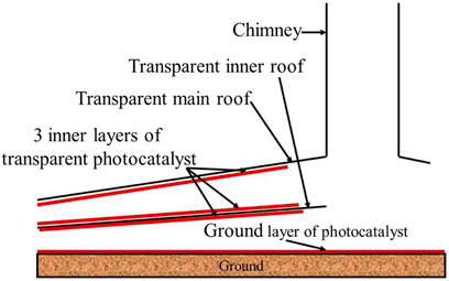
FIGURE 6. A SUT with double roof.
If the reaction rate of the photocatalyst is large enough to meet the reaction requirement only by coating part of the collector, it is suggested that the photocatalyst should be positioned toward the outer rim of the collector rather than the center. Under the collector, with the air flow to the center, the velocity steadily rises. The rise of velocity intensifies the air turbulence, which is beneficial to the mass transfer process. But it also reduces the contact time between methane and photocatalyst. Since the reaction is the bottleneck of the whole process, it is reasonable to coat the catalyst on the periphery of the collector.
Light Intensity and Quantum Efficiency
Light availability and penetration to the catalyst could present a further limitation, according to the quantum efficiency of the photocatalytic reaction. During photocatalytic process where photons strike photocatalyst surface, stimulate charge carriers inside photocatalyst and then the charge carriers move to photocatalyst surface and react with CH4 molecules. Apparent quantum yield (AQY), defined in Eq. 18, is widely used in heterogeneous photocatalysis (solid/liquid or solid/gas systems) to quantify the efficiency of photocatalysts or photocatalytic processes.
Assuming that only UV light can be used for the total oxidation of methane, and the ground under collector (46,760 m2) are equipped with photocatalysts, all methane passing through 50 kW SUT can be removed with an AQY of 5.2%. Similarly, we calculated the required AQY of 1.7% for a 200 MW SUT which has a greenhouse area of 3.8 × 10⁷ m2, summarized in Table 7.
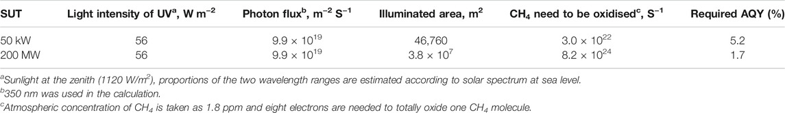
TABLE 7. Estimation of AQY required in a SUT for total removal of atmospheric CH4.
Night Operation Strategies
Another challenge of solar photocatalysis is night operation. On the ground under canopy, a thermal energy storage layer can be applied to store heat during the day and to release heat at night, driving airflow and allowing electricity production 24 h/day with no-intermittency (Ming et al., 2021). As a consequence, there can be some feasible strategy to utilize a small part of generated power to drive photocatalysis at night. Among those possibilities, at least two options for photocatalytic research are directly related.
1) Using artificial illumination at night onto all/part of the existing photocatalytic areas. In this option, almost all research outcomes about photocatalyst will stand and be applicable.
2) Considering the nature of methane at climatically relevant scale (i.e. significant amount of airflow and extreme dilution of the greenhouse gas), we can also propose another efficient and process intensified technology: an internal-illuminated monolithic photoreactor with distributed optical fibers. The technology is pioneered by Lin and Valsaraj in photocatalytic wastewater treatment (Lin and Valsaraj, 2005), adapted into a gas-liquid-solid multiphase photocatalysis by Du et al. (2008), and applied in gas phase photocatalysis by Liou (Liou et al., 2011) and Lu (Lu et al., 2016). Large surface area per unit volume as well as low pressure drop under quick flow rate provided by the monolith can be extremely beneficial. Side light optical fibres can distribute light into the entire inner surface of every channel.
Dimension of SUT
1) Height of the tower
The tower height not only determines the energy output of SUT, but also affects the outlet velocity, which is related to the amount of air flowing through SUT, the velocity and the residence time of air under the collector.
It can be seen from Eq. 19 that the outlet air speed of the tower increases with the increase of tower height, which means that more air will flow through the SUT collector with high tower, and the contact time between methane and photocatalyst is shorter Therefore, on the premise of meeting the energy output requirements, lower tower is conducive to improve the methane removal rate.
2) Radius of Collector
The large radius collector can provide larger contact area and longer residence time, but at the same time, it reduces the inlet velocity and thus weakens the mass transfer. For the process in which photocatalytic reaction is the rate-limiting step, it is suggested to build a collector with large radius. But larger collectors mean higher investment and maintenance costs. Therefore, the collector radius needs to be considered comprehensively. It should be pointed out that from the perspective of energy output, there is an up-limit on the radius of the collector, larger radius than that will not produce more power output (Li et al., 2012).
Temperature
In respect to the reaction rate, although methane oxidation is an exothermal reaction, Chen et al. conducted experiments under different temperatures and concluded that temperature fluctuation has little effect on the photo-oxidation process (Chen et al., 2016). At the mass transfer side, status of air flow is the major factor for mass transfer. Air flow under the collector mainly depends on temperature change (∆T) and tower height (HT) (Schlaich et al., 2005), and the influence of ambient temperature (Ta) on ∆T and HT is negligible. Therefore, it is believed that temperature might not be a major influencer for air flow and thus should not be a major influencer for mass transfer.
Conclusion
In this article, feasibility of SUTs as photocatalytic reactors for removal of atmospheric methane was evaluated. We examined the role of catalysts and rate limiting steps in particular.
The main findings are, 1) The effectiveness of combining photocatalysis with SUTs highly depends on the efficacy of photocatalysts and the size of SUT. More effective 0.1-Ag-ZnO photocatalyst can remove17.5 and 42.5% of methane in 50 kW and 200 MW SUTs respectively, while less effective TiO2 can only remove 0.4 and 1.4%. 2) If the more effective 0.1-Ag-ZnO photocatalyst is applied, in a 50 kW SUT, reaction and mass transfer jointly control the whole process, while in a 200 MW SUT, only reaction is the rate limiting step.
Outlook for future work to further improve the methane removal rate includes, 1) developing more effective photocatalysts, 2) increase catalyst coating area, 3) optimizing SUT geometry and 4) exploring night operation strategies.
Data Availability Statement
The original contributions presented in the study are included in the article/Supplementary Material, further inquiries can be directed to the corresponding author.
Author Contributions
YH, PD, RR, and WL initialized the idea and structure of the manuscript. YH, YS, and YB wrote the draft. QY, TM, PD, XL, RR, and WL refined, revised and edited the manuscript.
Funding
This research was also supported by the National Key Research and Development Plan (Key Special Project of Inter-governmental National Scientific and Technological Innovation Cooperation, Grant No. 2019YFE0197500), the European Commission H2020 Marie S Curie Research and Innovation Staff Exchange (RISE) award (Grant No. 871998), Nantong Science and technology project (Grant No. JC2021008).
Conflict of Interest
The authors declare that the research was conducted in the absence of any commercial or financial relationships that could be construed as a potential conflict of interest.
Publisher’s Note
All claims expressed in this article are solely those of the authors and do not necessarily represent those of their affiliated organizations, or those of the publisher, the editors and the reviewers. Any product that may be evaluated in this article, or claim that may be made by its manufacturer, is not guaranteed or endorsed by the publisher.
Acknowledgments
We gratefully acknowledge the support of Jiangsu Overseas Visiting Scholar Program for University Prominent Young and Mid-Aged Teachers and Presidents.
References
Aljaafari, A., Ahmed, F., Awada, C., and Shaalan, N. M. (2020). Flower-Like ZnO Nanorods Synthesized by Microwave-Assisted One-Pot Method for Detecting Reducing Gases: Structural Properties and Sensing Reversibility. Front. Chem. 8, 456. doi:10.3389/fchem.2020.00456
Brudvig, G. W., and Campagna, S. (2017). Introduction to a Themed Issue of Chemical Society Reviews on Artificial Photosynthesis. Chem. Soc. Rev. 46, 6085–6087. doi:10.1039/c7cs90096a
Cao, Q., Pui, D. Y. H., and Lipiński, W. (2015). A Concept of a Novel Solar-Assisted Large-Scale Cleaning System (SALSCS) for Urban Air Remediation. Aerosol Air Qual. Res. 15, 1–10. doi:10.4209/aaqr.2014.10.0246
Chen, X., Li, Y., Pan, X., Cortie, D., Huang, X., and Yi, Z. (2016). Photocatalytic Oxidation of Methane over Silver Decorated Zinc Oxide Nanocatalysts. Nat. Commun. 7, 1–8. doi:10.1038/ncomms12273
de_Richter, R., and Caillol, S. (2011). Fighting Global Warming: The Potential of Photocatalysis against CO2, CH4, N2O, CFCs, Tropospheric O3, BC and Other Major Contributors to Climate Change. J. Photochem. Photobiol. C: Photochem. Rev. 12, 1–19. doi:10.1016/j.jphotochemrev.2011.05.002
de_Richter, R. K., Ming, T., Caillol, S., and Liu, W. (2016). Fighting Global Warming by GHG Removal: Destroying CFCs and HCFCs in Solar-Wind Power Plant Hybrids Producing Renewable Energy with No-Intermittency. Int. J. Greenhouse Gas Control. 49, 449–472. doi:10.1016/j.ijggc.2016.02.027
de_Richter, R., Ming, T., Davies, P., Liu, W., and Caillol, S. (2017). Removal of Non-CO 2 Greenhouse Gases by Large-Scale Atmospheric Solar Photocatalysis. Prog. Energ. Combustion Sci. 60, 68–96. doi:10.1016/j.pecs.2017.01.001
Du, P., Carneiro, J. T., Moulijn, J. A., and Mul, G. (2008). A Novel Photocatalytic Monolith Reactor for Multiphase Heterogeneous Photocatalysis. Appl. Catal. A: Gen. 334, 119–128. doi:10.1016/j.apcata.2007.09.045
Fogler, H. S. (2016). “11. External Diffusion Effects on Heterogeneous Reactions,” in In Elements of Chemical Reaction Engineering. Editor H. S. Fogler. 4th ed. (Upper Saddle Rivier, NJ: Pearson Education, Inc.).
Haaf, W., Friedrich, K., Mayr, G., and Schlaich, J. (1983). Solar Chimneys Part I: Principle and Construction of the Pilot Plant in Manzanares. Int. J. Solar Energ. 2, 3–20. doi:10.1080/01425918308909911
Haeger, A., Kleinschmidt, O., and Hesse, D. (2004b). Kinetics of Photocatalyzed Gas Reactions Using Titanium Dioxide as the Catalyst Part II: Photocatalyzed Total Oxidation of Alkanes with Oxygen. Chem. Eng. Technol. 27, 1019–1026. doi:10.1002/ceat.200402073
Haeger, A., Kleinschmidt, O., and Hesse, D. (2004a). Kinetics of Photocatalyzed Gas Reactions Using Titanium Dioxide as the Catalyst- Part I: Photocatalyzed Total Oxidation of Olefines with Oxygen. Chem. Eng. Technol. 27, 181–188. doi:10.1002/ceat.200401890
Hisatomi, T., and Domen, K. (2017). Introductory Lecture: Sunlight-Driven Water Splitting and Carbon Dioxide Reduction by Heterogeneous Semiconductor Systems as Key Processes in Artificial Photosynthesis. Faraday Discuss. 198, 11–35. doi:10.1039/c6fd00221h
Jackson, R. B., Solomon, E. I., Canadell, J. G., Cargnello, M., and Field, C. B. (2019). Methane Removal and Atmospheric Restoration. Nat. Sustain. 2, 436–438. doi:10.1038/s41893-019-029-x10.1038/s41893-019-0299-x
Jiang, S., Lin, K., and Cai, M. (2020). ZnO Nanomaterials: Current Advancements in Antibacterial Mechanisms and Applications. Front. Chem. 8, 580. doi:10.3389/fchem.2020.00580
Jin, Y., Su, S., Liu, G., and Kang, X. (2017). Proof-of-concept Photocatalytic Destruction of Methane for Coal Mining Fugitive Emissions Abatement. Final Report of ACARP Project C24061. Available at: www.acarp.com.au/abstracts.aspx?repId=C24061ieved (Accessed April 18, 2021).
Kleinschmidt, O., and Hesse, D. (2002). Kinetics of the Photocatalytic Total Oxidation of Different Alkanes and Alkenes on TiO2 Powder. Can. J. Chem. Eng. 80, 71–78. doi:10.1002/cjce.5450800108
Kolster, C., Mechleri, E., Krevor, S., and Mac Dowell, N. (2017). The Role of CO 2 Purification and Transport Networks in Carbon Capture and Storage Cost Reduction. Int. J. Greenhouse Gas Control. 58, 127–141. doi:10.1016/j.ijggc.2017.01.014
Krishna, V., Kamble, V. S., Selvam, P., and Gupta, N. M. (2004). Sunlight-assisted Photocatalytic Oxidation of Methane over Uranyl-Anchored MCM-41. Catal. Lett. 98, 113–116. doi:10.1007/s10562-0047924610.1007/s10562-004-7924-6
Kuramochi, T., Ramírez, A., Turkenburg, W., and Faaij, A. (2012). Comparative Assessment of CO2 Capture Technologies for Carbon-Intensive Industrial Processes. Prog. Energ. Combustion Sci. 38, 87–112. doi:10.1016/j.pecs.2011.05.001
Leung, D. Y. C., Caramanna, G., and Maroto-Valer, M. M. (2014). An Overview of Current Status of Carbon Dioxide Capture and Storage Technologies. Renew. Sust. Energ. Reviewsenew 39, 426–443. doi:10.1016/j.rser.2014.07.093
Li, J.-y., Guo, P.-h., and Wang, Y. (2012). Effects of Collector Radius and Chimney Height on Power Output of a Solar Chimney Power Plant with Turbines. Renew. Energ. 47, 21–28. doi:10.1016/j.renene.2012.03.018
Li, W., Zhuang, C., Li, Y., Gao, C., Jiang, W., Sun, Z., et al. (2021). Anchoring Ultra-small TiO2 Quantum Dots onto Ultra-thin and Large-Sized Mxene Nanosheets for Highly Efficient Photocatalytic Water Splitting. Ceramics Int. 47, 21769–21776. doi:10.1016/j.ceramint.2021.04.192
Lin, H., and Valsaraj, K. T. (2005). Development of an Optical Fiber Monolith Reactor for Photocatalytic Wastewater Treatment. J. Appl. Electrochem. 35, 699–708. doi:10.1007/s10800-005-1364-x
Liou, P.-Y., Chen, S.-C., Wu, J. C. S., Liu, D., Mackintosh, S., Maroto-Valer, M., et al. (2011). Photocatalytic CO2 Reduction Using an Internally Illuminated Monolith Photoreactor. Energy Environ. Sci. 4, 1487–1494. doi:10.1039/c0ee00609b
Liu, Q., Li, N., Qiao, Z., Li, W., Wang, L., Zhu, S., et al. (2019). The Multiple Promotion Effects of Ammonium Phosphate-Modified Ag3PO4 on Photocatalytic Performance. Front. Chem. 7, 866. doi:10.3389/fchem.2019.00866
Liu, Y., Ming, T. Z., Ming, T., Peng, C., Wu, Y., Li, W., et al. (2021). Mitigating Air Pollution Strategies Based on Solar Chimneys. Solar Energy 218, 11–27. doi:10.1016/j.solener.2021.02.021
Lu, K.-T., Nguyen, V.-H., Yu, Y.-H., Yu, C.-C., Wu, J. C. S., Chang, L.-M., et al. (2016). An Internal-Illuminated Monolith Photoreactor towards Efficient Photocatalytic Degradation of Ppb-Level Isopropyl Alcohol. Chem. Eng. J. 296, 11–18. doi:10.1016/j.cej.2016.03.097
Massman, W. J. (1998). A Review of the Molecular Diffusivities of H2O, CO2, CH4, CO, O3, SO2, NH3, N2O, NO, and NO2 in Air, O2 and N2 Near STP. Atmos. Environ. 32, 1111–1127. doi:10.1016/S1352-2310(97)00391-9
Masson-Delmotte, V., Zhai, P., Pörtner, H. O., Roberts, D., Skea, J., Shukla, P. R., et al. (2018). Intergovernmental Panel on Climate Change, Special Report: Global Warming of 1.5 °C. Available at: https://www.ipcc.ch/sr15/.
Minami, W., and Kim, H.-J. (2006). Decomposition of Halocarbons Using TiO2 Photocatalyst. Kagaku Kogaku Ronbunshu 32, 310–313. doi:10.1252/kakoronbunshu.32.310
Ming, T., Gui, H., Shi, T., Xiong, H., Wu, Y., Shao, Y., et al. (2021). Solar Chimney Power Plant Integrated with a Photocatalytic Reactor to Remove Atmospheric Methane: A Numerical Analysis. Solar Energy 226, 101–111. doi:10.1016/j.solener.2021.08.024
Pretorius, J. P. (2007). Optimization and Control of a Large-Scale Solar Chimney Power Plant. [Ph.D. dissertation]. [South Africa]. University of Stellenbosch.
Qi, K., Liu, S.-y., and Zada, A. (2020b). Graphitic Carbon Nitride, a Polymer Photocatalyst. J. Taiwan Inst. Chem. Eng. 109, 111–123. doi:10.1016/j.jtice.2020.02.012
Qi, K., Lv, W., Khan, I., and Liu, S.-y. (2020c). Photocatalytic H2 Generation via CoP Quantum-Dot-Modified G-C3n4 Synthesized by Electroless Plating. Chin. J. Catal. 41, 114–121. doi:10.1016/S1872-2067(19)63459-5
Qi, K., Xing, X., Zada, A., Li, M., Wang, Q., Liu, S.-y., et al. (2020d). Transition Metal Doped ZnO Nanoparticles with Enhanced Photocatalytic and Antibacterial Performances: Experimental and DFT Studies. Ceramics Int. 46, 1494–1502. doi:10.1016/j.ceramint.2019.09.116
Qi, K., Zada, A., Yang, Y., Chen, Q., and Khataee, A. (2020a). Design of 2D-2D NiO/g-C3n4 Heterojunction Photocatalysts for Degradation of an Emerging Pollutant. Res. Chem. Intermed 46, 5281–5295. doi:10.1007/s11164-020-04262-0
Schlaich, J. r., Bergermann, R., Schiel, W., and Weinrebe, G. (2005). Design of Commercial Solar Updraft tower Systems-Utilization of Solar Induced Convective Flows for Power Generation. J. Sol. Energ. Eng. 127, 117–124. doi:10.1115/1.1823493
Sekar, K., Chuaicham, C., Balijapalli, U., Li, W., Wilson, K., F. Lee, A., et al. (2021). Surfactant- and Template-free Hydrothermal Assembly of Cu2O Visible Light Photocatalysts for Trimethoprim Degradation. Appl. Catal. B: Environ. 284, 119741. doi:10.1016/j.apcatb.2020.119741
Sekar, K., Chuaicham, C., Pawar, R. R., Sasaki, K., Li, W., Lee, A. F., et al. (2019). Template Free Mild Hydrothermal Synthesis of Core-Shell Cu2O(Cu)@CuO Visible Light Photocatalysts for N-Acetyl-Para-Aminophenol Degradation. J. Mater. Chem. A. 7, 20767–20777. doi:10.1039/C9TA07009E
Sikkema, J. K., and dissertation, Ph. D. (2013). Photocatalytic Degradation of NOx by concrete Pavement Containing TiO2. [Ames]: Iowa State University.
United States Environmental Protection Agency (US EPA) (2013). Global Mitigation of non-CO2 Greenhouse Gases: 2010-2030. Report No. EPA-430-R-13-011.
Wang, J., Zhou, Q., Peng, S., Xu, L., and Zeng, W. (2020). Volatile Organic Compounds Gas Sensors Based on Molybdenum Oxides: a Mini Review. Front. Chem. 8, 339. doi:10.3389/fchem.2020.00339
Wetenhall, B., Aghajani, H., Chalmers, H., Benson, S. D., Ferrari, M.-C., Li, J., et al. (2014). Impact of CO2 Impurity on CO2 Compression, Liquefaction and Transportation. Energ. Proced. 63, 2764–2778. doi:10.1016/j.egypro.2014.11.299
Yang, L., Cai, A., Luo, C., Liu, Z., Shangguan, W., and Xi, T. (2009). Performance Analysis of a Novel TiO2-Coated Foam-Nickel PCO Air Purifier in HVAC Systems. Sep. Purif. Tech. 68, 232–237. doi:10.1016/j.seppur.2009.05.008
Zada, A., Khan, M., Qureshi, M. N., Liu, S.-y., and Wang, R. (2020). Accelerating Photocatalytic Hydrogen Production and Pollutant Degradation by Functionalizing G-C3n4 with SnO2. Front. Chem. 7, 941. doi:10.3389/fchem.2019.00941
Zhang, H., Li, Y., Li, W., Zhuang, C., Gao, C., Jiang, W., et al. (2021). Designing Large-Sized Cocatalysts for Fast Charge Separation towards Highly Efficient Visible-Light-Driven Hydrogen Evolution. Int. J. Hydrogen Energ. 46, 28545–28553. doi:10.1016/j.ijhydene.2021.06.134
Keywords: solar updraft, photocatalysis, non-CO2 greenhouse gases, methane, climate change
Citation: Huang Y, Shao Y, Bai Y, Yuan Q, Ming T, Davies P, Lu X, de Richter R and Li W (2021) Feasibility of Solar Updraft Towers as Photocatalytic Reactors for Removal of Atmospheric Methane–The Role of Catalysts and Rate Limiting Steps. Front. Chem. 9:745347. doi: 10.3389/fchem.2021.745347
Received: 21 July 2021; Accepted: 25 August 2021;
Published: 10 September 2021.
Edited by:
Pengyu Dong, Yancheng Institute of Technology, ChinaReviewed by:
Kezhen Qi, Shenyang Normal University, ChinaVincenzo Vaiano, University of Salerno, Italy
Copyright © 2021 Huang, Shao, Bai, Yuan, Ming, Davies, Lu, de Richter and Li. This is an open-access article distributed under the terms of the Creative Commons Attribution License (CC BY). The use, distribution or reproduction in other forums is permitted, provided the original author(s) and the copyright owner(s) are credited and that the original publication in this journal is cited, in accordance with accepted academic practice. No use, distribution or reproduction is permitted which does not comply with these terms.
*Correspondence: Wei Li, d2VpLmxpQGVkLmFjLnVr