- Center for Axion and Precision Physics Research, Institute for Basic Science, Daejeon, South Korea
COMET is an experiment at J-PARC, Japan, which will search for neutrinoless conversion of muons into electrons in the field of a nucleus (μ− + N → e− + N); a lepton flavor violating process. The experimental sensitivity goal for this process is order of 10−15 for Phase-I and 10−17 for Phase-II experiment, which is a factor of 100–10,000 improvements correspondingly over existing limits. Recent progresses in facility and detector development are presented, along with COMET Phase-I and Phase-II experimental schedule.
1. Introduction
The discovery of the Higgs boson at the LHC in 2012 provided a successful demonstration of the Standard Model (SM) of particle physics. However, this does not answer unresolved questions in particle physics, for example, the matter-dominated universe, dark matter, lack of quantum gravity, and neutrino mass. The neutrino oscillation discovered from a lot of neutrino experiments, during 1990s and still under active investigation, is an important motivation that forces to extend the SM. The SM extension with massive neutrino which enables neutrino oscillation and other theories beyond Standard Model (BSM) enlightens the charged lepton flavor violation (cLFV). As the lepton number and lepton flavor are conserved quantities in SM, observation of cLFV process will provide clues on BSM theories. The cLFV process of muon and tau leptons have been searched for a few decades, and COMET experiment is one of the most recent experiment in muon cLFV search.
The COMET (COherent Muon to Electron Transition, J-PARC E21) experiment [1] aims to search for neutrinoless muon conversion process in the field of nucleus, μ−e conversion, which is one of the most important cLFV processes. The COMET experiment is located at Japan Proton Accelerator Research Complex (J-PARC) in Tokai, Japan. The 8 GeV bunched proton beam from the main ring (MR) of J-PARC will be supplied to the Nuclear Physics Experiment hall (NP hall) where the COMET facility and the detectors are installed. The COMET experiment will be carried out in two stages. The first stage (Phase-I) will utilize half length transport solenoid and a drift chamber detector for measuring μ−e conversion signal down to O(10−15). A background measurement program will be also performed with Phase-I beamline including the study of detector prototype for Phase-II experiment. In the second stage (Phase-II), full length C-shape transport solenoid, spectrometer solenoid, and straw tube detectors will be used to achieve O(10−17) level of μ−e conversion measurement. These target sensitivities are 100 or 10,000 times better than the current experimental world limit given by SINDRUM-II experiment [2].
In this review, an introduction on the theoretical and experimental aspects of cLFV is reviewed in section 2, the design and status of facilities and detectors of COMET Phase-I experiment are described in section 3, its physics reach, in section 4. The design of Phase-II detector and background measurement program are described in section 5.
2. Charged Lepton Flavor Violation Experiment
2.1. Physics of Charged Lepton Flavor Violation
In the SM, all lepton numbers are conserved quantities, and their sum, the total lepton number is also conserved. The observation of neutrino oscillation forces minimal extension of the SM, so that the neutrino is now massive (but very light) particle. The neutrino oscillation is described by PMNS (Pontecorvo-Maki-Nakagawa-Sakata) matrix, just like the mixing of quarks described by CKM (Cabibbo-Kobayashi-Maskawa) matrix. This results in neutral lepton flavor violation.
While the neutrino oscillation does not break the symmetry of lepton number, it enables the cLFV, which is depicted in Figure 1A. The neutrino oscillation occurring in loop level induces radiative decay of charged lepton into another flavor. On the other hand, many BSM theories motivated by the unresolved questions of the SM, are predicting the cLFV independently to the minimal extension of the SM with massive and oscillating neutrinos. The estimated rates of cLFV in BSM theories are significantly bigger than the estimation in the SM. Therefore, observation of cLFV process can be a direct signature of BSM theories. Comparing with tau lepton, muon is the optimal particle to search for cLFV process, because of its much longer life time, easiness of production, and light mass which disables decay channels with hadrons. In case of easiness of production, the B-factory experiments had recorded 1~10 tau lepton pair productions per second, while the future muon conversion experiments will generate 1013~1014 muons per second. Therefore, the achievable sensitivity of muon cLFV is much lower than the tau lepton case.
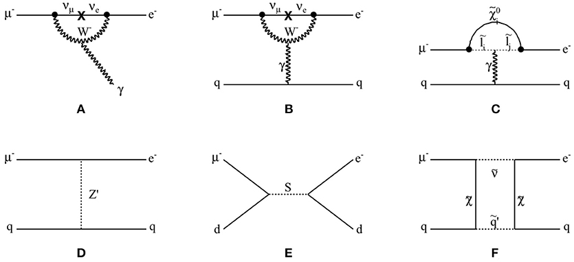
Figure 1. The diagrams of cLFV processes, (A) for μ+ → e + γ, and (B–F) for μ− + N → e− + N. (A) SM process due to massive neutrinos of μ+ → e + γ, (B) SM process due to massive neutrino of μ− + N → e− + N, (C) SUSY process in a loop diagram, (D) vector boson exchange process, and (E) s-channel scalar boson exchange process, and (F) SUSY process in a box diagram of μ− + N → e− + N.
The neutrinoless muon to electron conversion process in a muonic atom, μ− + N → e− + N, is one of the most important cLFV processes of muon, along with μ+ → e + γ and μ+ → e+e−e+ processes. A diagram of the μ−e conversion in the minimally extended SM is shown in Figure 1B. Comparing the μ+ → e + γ decay (depicted in Figure 1A) vs. μ−e conversion, the photon is observable in the μ+ → e + γ process. However in the μ−e conversion, the photon is a virtual photon interacting with nucleus. In BSM theories, for example Supersymmetry (SUSY) theory, and similarly with the μ+ → e + γ, the μ−e conversion can happen through a similar loop diagram that does not involve massive neutrino but charged SUSY particle with photon interaction to quarks, as shown in Figure 1C.
Despite this small difference between μ+ → e + γ and μ−e conversion, two cLFV processes are complementary, as μ−e conversion can occur through a different process. μ+ → e + γ will not be sensitive in the case of cLFV process through hypothetical direct lepton-quark interaction (Figures 1D–F). This is clear when writing effective Lagrangian of μ−e conversion process [3]:
The and terms are describing the effective couplings, and μ, e, u and d are describing the fields associated with the representing particles. Two free parameters are introduced, Λ describing the energy scale of the cLFV physics, and κ describing the relative strength of the two terms. Note that this equation is describing the effective Lagrangian, focusing on two possible dominating processes, which is derived from the full Lagrangian including all possible processes (shown in [4] and [5]). In this Lagrangian, the first term describes an electromagnetic dipole interaction by photon described by a field strength tensor Fμν. The second term describes a two-lepton and two-quark contact interaction. While the μ+ → e + γ exists and the process occurs through the electromagnetic dipole interaction (κ ≪ 1, the first term dominating case), then it suggests that μ−e conversion process should exist and be observed. On the other hand, the existence of μ−e conversion does not necessarily imply that μ+ → e + γ should exist, as μ−e conversion may occur through the contact interaction (κ ≫ 1, the second term dominating case). This difference between μ+ → e + γ and μ−e conversion leads different sensitivities to BSM theories, depending on the types of cLFV interaction (dipole or contact interactions). In order to understand the BSM theories, it is important to compare results between μ+ → e + γ and μ−e conversion experiments, and also between μ+ → e+e−e+ and μ−e conversion experiments, because of this different sensitivities to physics model of cLFV. The latest result of μ+ → e+e−e+ and the new generation experiment under construction (Mu3e experiment) are summarized in [6] and [7], respectively. It is also important to repeat μ−e conversion experiment with different muonic atom, as the expected μ−e conversion rate varies depending on the chiral structure of cLFV process, which again changes depending on the muonic atom material. See Kitano et al. [4] for detailed discussion.
Many BSM theories are suggesting μ−e conversion process. Figure 1D shows the tree level vector boson exchange process, where Z′ denotes a massive neutral vector boson. The Z′ is expected in, for example, grand unified theories (GUT) [8] with type-III seesaw mechanism, extra gauge group models [9], technicolor models [10], extra dimensional models [11, 12], or little Higgs models with T-parity [13]. Similar tree level interaction via scalar boson exchange is also possible, for example, when SUSY particle is violating R-parity [14, 15]. In the models with leptoquarks, lepton and quark are directly interacting, which results in a s-channel diagram as shown in Figure 1E. In this case, a scalar mediator particle is carrying lepton and hadron number together [16, 17].
Higher order cLFV process involving loop or box type interaction is more common in BSM theories. The mediating particle can be photon, Z, Higgs or any other new particle. The simplest example is R-parity conserving SUSY model [18–20], shown in Figures 1C,F, for loop diagram and box diagram, respectively. Other possible scenario includes SM extension with sterile neutrino [18, 21, 22], Type-II seesaw mechanism [23], or Left-Right symmetric models [24].
Whatever BSM theories are recalled, the expected μ−e conversion rate is significantly higher than SM process, because the SM process requires neutrino oscillations of which the rate is extremely small due to very tiny mass of neutrino, and heavy mass of mediating W-boson. In other words, SM process of μ−e conversion is suppressed by from the unitarity condition of PMNS matrix in GIM mechanism, where GF and mν are Fermi constant and neutrino mass, respectively. The μ−e conversion rate is normalized to the muon capture:
and its estimation in SM yields less than O(10−50). 1In comparison, the BSM process of cLFV might be enhanced depending on the masses and interactions of mediating BSM particles, which may lead observable rate of cLFV process in a modern particle physics experiments.
2.2. Experiments on Charged Lepton Flavor Violation
When the momentum of negative muon (μ−) 2 inside material is sufficiently low, it stops inside the material due to Coulomb field of atoms, and form muonic atom by orbiting around nucleus. Three processes are possible for the stopped muon: (1) muon can decay in the orbit (Decay-In-Orbit: DIO) without interacting with nucleus; (2) muon can interact with a proton of the nucleus through charged current, resulting into an excitation of the muonic atom; and (3) muon can decay through cLFV process, which is the target process of μ−e conversion experiment.
From the kinematics point of view, μ+ → e + γ have two final state particles which share the mass of muon exactly half and half. In the μ−e conversion process, the final state particle is only one electron, which carries most of muon mass energy. Therefore, the signal of μ−e conversion experiment is mono-energetic electron around muon mass. On the other hand, the tail of DIO spectrum extends nearly up to muon mass, therefore DIO is irreducible physics background. Most of other background events are originating from the beam. See details in section 4.
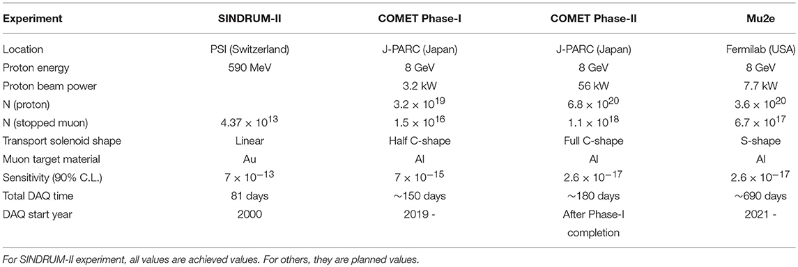
Historically, the cLFV experiments started in the early of 1960s. In case of μ+ → e + γ, the MEG experiment [28] provides current best limit [29, 30], B(μ+ → e+γ) < 4.2 × 10⁻¹³ (90 % C.L.). For μ−e conversion, the best upper limit, (90 % C.L.), is given by SINDRUM-II experiment [2]. The COMET experiment [1] at J-PARC, Japan, and Mu2e experiment [31] at Fermilab are next generation experiments for μ−e conversion measurements. The biggest difference with SINDRUM-II and COMET or Mu2e is the application of curved solenoids in the entire muon beam lines. This increases the muon transportation yield, as well as provides a method to suppress background beam particles. The COMET Phase-I experiment is targeting to achieve intermediate level of sensitivity between COMET Phase-II and SINDRUM-II experiments. The COMET Phase-II and Mu2e are similar in many aspects, however, they employ different shapes of muon transport solenoid. COMET Phase-II is focusing on utilizing high power proton beam and efficient DIO suppression, while Mu2e is focusing on higher detector efficiency. Table 1 compares important parameters of these experiments.
3. COMET Detector and Facility
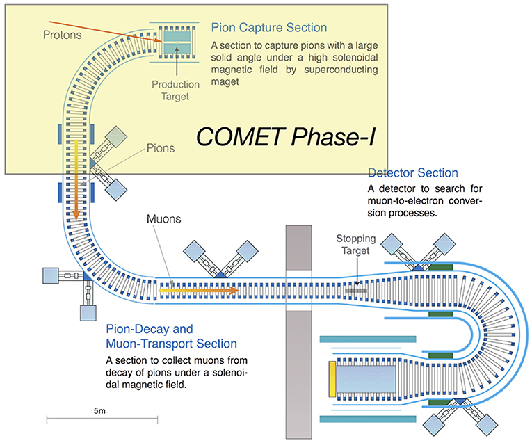
The muon beams are generated from the decays of pions which are generated by the proton beam collisions to target. In the COMET experiment, proton beam from J-PARC MR is injected to the proton target in order to generate pions. Pions are collected by solenoidal field and transported to the detector during its decay to muons. Muons delivered to the detector section stop at the muon target inside the detector, and when cLFV occurs, a single mono-energetic electron from muon decay is emitted from the muon target which is measured by the surrounding detectors. The COMET Phase-I experimental setup including the proton target, the muon transporting solenoid, and the detector are shown in Figure 2. From the right side to left, pion production and capture solenoid system, muon transport solenoid system, and detector system are shown. The proton beam enters to the pion capture solenoid system at an angle from the top left direction of the proton target which is drawn as red line in the center of pion capture solenoid. Muon transport solenoid system provides solenoidal field and dipole field, so that produced pion and its decay to muon are transported to detector system.
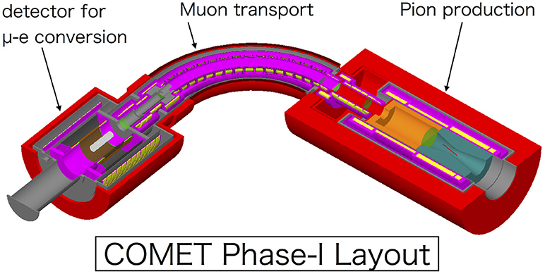
Figure 2. The layout of detectors and beamlines of COMET Phase-I experiment. The pion capture solenoid system with proton target in the center (right part), the muon transport solenoid system (middle part), and the CyDET detector system with muon stopping target in the center (left part) are shown. See the text for more description.
Two separate detector systems are under development for COMET Phase-I experiment. For measuring μ−e conversion, the CyDET (Cylindrical DETector system) detector system will be used. The CyDET is composed of a cylindrical drift chamber and scintillator counters. The muon stopping target locates at the center of the cylindrical drift chamber, which is drawn as gray cylinder in the Figure 2. After the experiment, a special beam measurement program is planned for a direct estimation of the beam-related background. This background estimation will be applicable to the tuning of simulation and sensitivity estimation of Phase-II experiment. The detector for beam measurement program is called StrECAL, where details will be discussed in section 5. The difference of solenoid system is the reason of choosing different detector system for Phase-I and Phase-II. In Phase-II, full length pion and muon transport solenoid, and curved electron transport solenoid will be installed before the detector system. These additional solenoid system effectively filters lower and higher momentum particles except the electron momentum from muon conversion. This reduces a lot of the beam background. Even though using 56 kW beam in Phase-II which is 17.5 times more powerful than Phase-I, these momentum filtering reduces hit rate a lot where the straw detector system can manage. In contrast, even though using 3.2 kW beam in Phase-I, the hit rate is expected high due to the beam particles. Cylindrical drift chamber is employed so that beam particles pass the center hole when it does not hit muon stopping target, and does not affect the detector.
3.1. Accelerator for the COMET Experiment
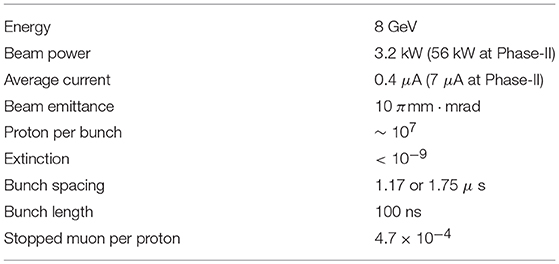
Table 2 summarizes the specification of COMET proton beam. The COMET experiment is utilizing pulsed protons as primary beam. The captured muons in the muon stopping target materials decay with finite life time in the order of 1μs, while the background events coming from the pion decays or other beam particles are not structured in time. The pulsed muon beam is required to avoid these beam related backgrounds out of muon capture event, by applying pre-defined measurement time window between proton pulses. Considering the lifetime of captured muon, 1~2μs bunch spacing is required. The straying beam particles during bunch spacing generates background events in the measurement time window, therefore the inter-beam particles should be suppressed. This inter-beam extinction is one of the most important requirements of the COMET experiment, defined by the number of straying inter-beam particles (mostly protons) divided by the number of protons in the bunch. The requirement of this extinction factor in the COMET experiment is O(10−9), where extinction measurements at the proton extraction line to long-baseline neutrino experiments (“Fast extraction”) have achieved O(10−11).
The 8 GeV proton beam for the COMET experiment is extracted from the MR of J-PARC to the NP hall, which get filled by primary proton LINAC, followed by 3 GeV Synchrotron (RCS: Rapid Circulating Synchrotron). The beam energy is chosen so that the anti-proton production is minimized during the collision at proton target, and the extinction of inter-beam proton is maximized. The anti-proton production increases rapidly above 10 GeV proton energy. Lower energy proton beam is easier to deflect to make higher extinction beam. Special beam injection method from RCS to MR (“Single Bunch Kicking”) that advances injection kicking time around 600 ns in order to avoid empty bucket kicking is developed. For beam extraction from MR to NP hall, the RF voltage is kept high in order to maintain the pulse structure and to avoid deterioration of extinction factor (“Bunched Slow Extraction”). Tests with accelerator showed that achieving 10−12 extinction is possible by keeping RF voltage of 255 kV.
The harmonic number of MR is nine, which means nine beam bunches are able to circulate the MR at the same time. However, not all beam buckets are filled, in order to keep the fixed bunch spacing which is required in the COMET experiment. Filling three buckets out of nine buckets (one filled bucket and two subsequent empty bucket) results in 1.75 μs proton pulse spacing, or filling four even order buckets only results in 1.17 μs proton pulse spacing. Both filling schemes satisfy beam pulse requirement, however, 1.17 μs spacing is favorable to deliver more protons, and 1.75 μs spacing is favorable in longer measurement time window. The 1.17 μs spacing scheme is shown in Figure 3 along with the overview of J-PARC facility.
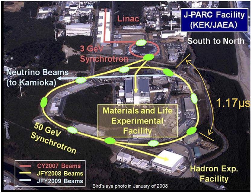
Figure 3. The J-PARC facility. The primary proton driver LINAC and 3 GeV RCS beam lines are shown in red. The MR and related beamlines to NP hall where the COMET experiment locates (“Hadron experimental facility” at the bottom right) are shown in yellow. Note that maximum storage beam energy of MR is 50 GeV while the COMET experiment will use 8 GeV beam. The filled and hollow green circles around MR and RCS beamlines are filled and empty proton buckets, respectively. As written in the text, not all buckets are filled to maintain required bunch spacing between proton pulses. The photo credit of bird-eye view goes to J-PARC.
3.2. Proton Beamline
The COMET experiment is built in the NP Hall, along with a new beam line called B-line, which is under construction. The existing beam line (A-line) from the MR is serving various hadron experiments in NP hall. The B-line is split into two beam lines, one for 30 GeV high-momentum experiment and the other for the COMET experiment. During the standard high-momentum running, the A-line and B-line share the beam in the ratio of 10,000:1. In the low-momentum running for COMET, the entire beam is sent to the B-line. To enable this beam sharing, a Lambertson magnet and two subsequent septum magnets are configured at the branch of A- and B- line.
A special proton beam monitoring detector will be installed at the end of proton beam line before COMET solenoid system. The purposes of this detector are (1) monitoring the beam extinction in order to reject data with poor extinction; and (2) monitoring the beam position in order to avoid misalignment of beam. As the monitoring detector will be located inside the beam line flange connecting the proton beam line to the COMET solenoid system, high fluence up to 1016/cm2 is expected. Also, to measure timing structure of beam for extinction measurement, fast response and charge collection at around 10 ns level is required. A detector utilizing CVD (Chemical Vapor Deposition) Diamond shows good performances in tests, and is now under development.
The delivered protons will hit the target and generate pions. The proton target locates inside capture solenoid system providing 5 T solenoidal magnetic field. The field strength decreases to 3 T at the entrance of pion and muon transport solenoid. As proton target material, Graphite or Tungsten will be used for Phase-I and Phase-II, respectively. While Tungsten target will produce more pions due to heavier atomic mass, it will be carefully designed including water (or other coolant) cooling method in order to handle the heats. From simulation studies, the average momentum of forward directing pions (to the proton beam direction) is estimated to be around 200–400 MeV/c, where that of backward pions is around 150 MeV/c. It is also found that a lot of a few GeV pions are generated in forward pions, when the low momentum pion yield are similar for backward and forward pions. High momentum pions are not preferred because it decays to high momentum muons which will not lose sufficient energy in the thin muon stopping target and do not stop there. Also longer lifetime of high momentum pions will result in pion decays inside the detector solenoid that become backgrounds. Therefore, the backward directing pions are collected in the COMET experiment. The designed proton target for Phase-I experiment is 13 mm radius and 700 mm length with Graphite material, which is designed so that it can be replaced in Phase-II experiment to Tungsten target.
3.3. Pion and Muon Beam Line
The pions generated at the proton target pass the muon transport solenoid system. Charged particles follow helical trajectories in a solenoidal field. In a curved solenoid, the central axis of this trajectory drifts in the direction perpendicular to the plane of beam center. The magnitude of this drift, D, is given by
where is momentum, pL and pT are longitudinal and transverse momentum, respectively, q is the electric charge of the particle, B is the solenoidal magnetic field at the beam axis, s is the path length along the beam axis, R is radius of solenoid system, and θ is the pitch angle of initial momentum of particle. For adjusting the beam trajectories drifting out of the beam axis plain which eventually results in beam misalignment and loss, two different solutions can be implemented. One solution is to apply compensation dipole field parallel to the drift direction, which effectively tilts the solenoidal field toward the opposite direction from the drift direction otherwise applied. The compensation dipole field, Bcomp, is obtained as
Another solution is to have oppositely bending subsequent transport solenoid with the same bending angle. This solution is adopted in Mu2e experiment. It should be also noticed that the drift direction is opposite to the different charge particles. This separates trajectories depending on the particle charge, and enables charge selection of beam. In the COMET experiment, positive pions and muons are filtered out using proper collimator at the end of the transport solenoid.
As shown in Figure 9 and described in section 5, in COMET Phase-II experiment, a complete C-shape transport solenoid with 180° will be installed, however, the half length 90° solenoid will be used in the Phase-I experiment, as a staged approach of solenoid construction. The strength of solenoidal field is 3 T, where compensation dipole field strength is around 500 Gauss.
3.4. The COMET Phase-I Detectors
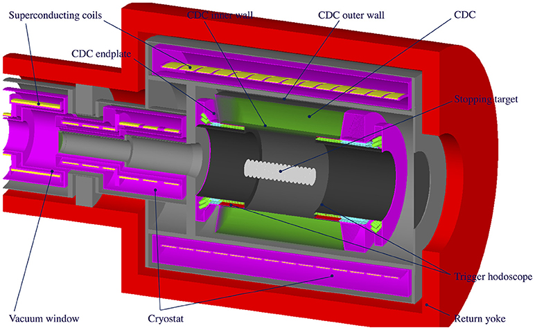
The CyDET, shown in Figure 4, is composed of a Cylindrical Drift Chamber (CDC) and two trigger hodoscope arrays, which are located inside the detector solenoid system providing 1 T solenoidal field. At the center of CDC there is the muon stopping target system composed of Aluminum disks, where the muons are captured.
The CDC is a conventional drift chamber, with around 5,000 wires, structured into 39 layers. First and last layers are guard layers, even order layers are field layers, and odd layers are sense layers, where field wires are grounded, and sense wires are energized to around 1.7 kV. The stereo angle of sense layers are alternating positive and negative. The inner and outer radii are around 500 and 850 mm, respectively, which are determined in order to cover full track of 105 MeV electron from muon conversion, and reject electrons less than 60 MeV. The requirement of momentum resolution is 200 keV/c for 105 MeV electron, to achieve designed experimental sensitivity. In order to reduce the multiple scattering effects that affects the momentum resolution in low momentum measurements, the CDC is designed to be low mass as possible. The spatial resolution better than 200 μm is measured during cosmic ray tests. The baseline choice of CDC gas is Helium and Isobutane (90:10) mixture.
Two trigger hodoscope arrays (CTH: CyDET Trigger Hodoscope) surround both inner edges of CDC, where each array is composed of 48 sets of scintillator and Cerenkov detector pairs. Direction of each detector modules are innerly tilted, and they are overlapped around half depth. When μ−e conversion occurs, the helical trajectory inside 1 T solenoidal field generates CDC hits and subsequently hodoscope hits. These hodoscope hits are primary trigger of conversion electron. From simulation study, the primary CTH hit rate is estimated to be around a few MHz. This very high rate is due to the beam particles, and Bremsstrahlung from Michel electrons produced in muon decay at rest in the muon stopping target. To reduce the hit rate and provide manageable rate of primary trigger, 16 mm lead shielding is added in the inner part of CTH ring. Also coincidence is required for 2 adjacent hodoscope pairs (4 scintillator or Cerenkov detector modules), benefiting from the tilted and overlapped structure. After application of these methods, the trigger rate is estimated to 19 ~ 26 kHz, depending on the length of measurement time window after beam flash. Note that, during the beam flash timing, the CTH hit rate is much higher due to beam particles, and the measurement time window is set a few hundred ns after beam flash to avoid the effects from beam flash.
At the center of CDC and detector solenoid, the muon stopping targets are located. Aluminum is chosen as muon target material considering the lifetime of a muonic atom and expected cLFV process rate for different chiral currents in different theories. The lifetime of Aluminum muonic atom (Z = 13) is around 0.88 μs. This is decreasing with increasing atomic number, therefore, high Z material is not preferred as muon target material. Another candidate material is Titanium (Z = 22) with muonic atom lifetime 0.33 μs. 17 Aluminum flat disks of 200 μm thickness and 100 mm radius are placed with 50 mm spacing.
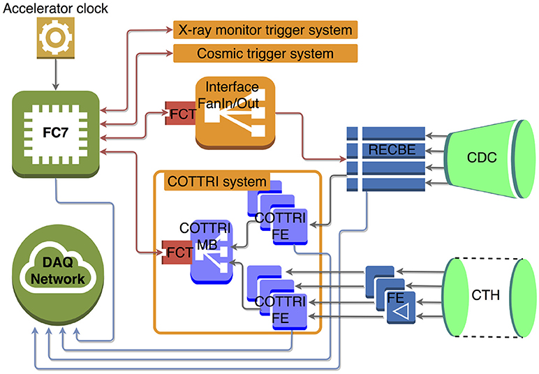
The CDC and CTH signals are read out by custom readout boards, RECBE and COTTRI, respectively. The RECBE boards are originally developed as Belle-II CDC readout [32], and are customized for the use in COMET CDC readout. One RECBE board processes signals from 48 CDC channels, amplifying and digitizing, and send the ADC and TDC data to data acquisition (DAQ) system. It also sends hit information to trigger process board, the COTTRI (COmet TRIgger board). The COTTRI system [composed of several frontend boards (FE) and one or two mother boards (MB)] is used for digitizer board of CTH detectors, as well as timing data processor board from CDC. The processed hit and timing information of CDC combined with CTH hit information are sent to central trigger system. In this trigger chain, the CDC hit information is also used for generating final trigger decision, therefore, it effectively reduces the trigger rate down to O(kHz) level by rejecting background events.
This design of trigger system is shown in Figure 5. In the design of the central trigger and timing system, the main trigger processor board is FC7 board [33], which has been developed for the CMS experiment at CERN. It collects primary trigger, decides final trigger decision, and provides it with control clock to the readout boards. To keep the commonality between FC7 and readout or trigger board connections using 4.8 Gbps optical serial link, a custom FPGA board (FCT board) is developed which will be connected to the readout or trigger boards. The DAQ system is based on MIDAS (Maximum Integrated Data Acquisition System) [34] frameworks.
4. Physics Reach of the COMET Phase-I Experiment
To understand the physics reach of the COMET experiment, a GEANT4 [35] based simulation framework called “ICEDUST” has been developed. The ICEDUST (Integrated Comet Experimental Data User Software Toolkit) framework is based on the framework used for the ND280 experiment. While the detector response simulation is mostly managed by GEANT4, the true particle generations and their decays can be simulated with external Monte Carlo packages, such as MARS [36], FLUKA [37], or PHITS [38]. A special physics process description is incorporated for muon capture process into ICEDUST.
4.1. Signal and Backgrounds in COMET Phase-I Experiment
The signal of μ−e conversion is a single mono-energetic electron with an energy of:
where mμ is the mass of muon, Bμ is the binding energy of muonic atom in 1s state, and Erecoil is the energy loss of emitting electron due to the recoil of nuclei. The momentum of the signal (or background) electron will be measured by CDC of CyDET in the case of COMET Phase-I, or by straw detector of StrECAL in the case of COMET Phase-II.
The electron track and its momentum can be reconstructed by applying hit selection, track finding, and track fitting algorithms. In the track fitting procedure, elimination of background hits are very important to have good track fitting results. The hits generated by highly ionizing particles such as proton are easily rejected by applying criteria on energy deposition in the CDC wire. This simple method does not work in rejecting hits from delta-rays, electron-positron pair created by photon backgrounds mostly coming from muon stopping target, or charged particles generated primary by neutrons, all with low energy and with short path lengths in the CDC. In contrast, conversion signal electrons or high energy DIO electrons generate helical trajectories in CDC, which can be distinguishable by their shapes. Therefore, the first procedure in the signal analysis is to identify CDC hits from signal electrons out of background hits. From simulation study with ICEDUST with signal and background overlaid data sample, it is found that applying Gradient Boosted Decision Tree (GBDT) algorithm with input feature of energy deposition of sense wire, energy deposition of neighboring sense wire, and layer number, is quite effective to discriminate background hits. Preliminary result shows around 95% signal retaining when 99% background hits can be removed. Figure 6 shows one example of GBDT application in the hit selection. This algorithm can be applied not only at the data analysis stage, but also at the trigger level in COTTRI, to further reduce the background hits and the trigger rate. After hit selection, track candidates are found by using either the Hough transformation or the Neural network. The Kalman filtering method can be used in the track fitting for the signal momentum estimation.
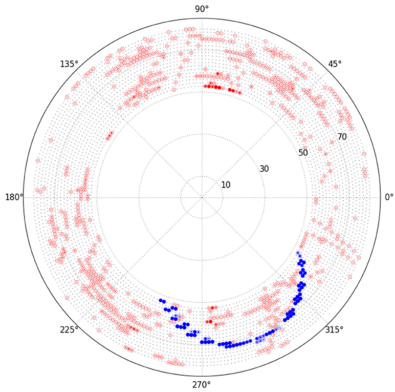
Figure 6. A visual representation of the hit level GBDT applied to the signal event with background hits. The red and blue filled circles are passed hits by GBDT application, while empty circles are rejected. Big blue arc pattern is a signal electron.
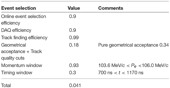
The signal acceptance of Phase-I experiment is estimated under ICEDUST simulation study, and Table 3 shows the result. The major inefficiencies are coming from the geometry of CDC which is not 4π detector. Pure geometric acceptance is around 34 %, and the requirement of a 4-fold coincidence together with track quality selection reduce the efficiency to 18 %. It should be noted that track quality selection is preliminary result and can be improved with real data. Benefiting from a good CDC resolution performance, momentum window criteria do not significantly affect the efficiency. In this estimation, the measurement time window is set from 700 ns after the beam pulse, up to 1,170 ns, assuming a bunch spacing of 1.17 μs. Longer bunch spacing will increase the efficiency, sacrificing the total DAQ time. Advancing the starting time of measurement time window up to 500 ns can be considered to increase efficiency. The overall signal acceptance is estimated to around 4.1%.
For the background events of the COMET experiment, they can be categorized into physics backgrounds and beam-related backgrounds.
The physics backgrounds are consequence of muonic atom.
(1) Decay-in-Orbit (DIO),
is the muon decay in a muonic atom without interaction with nucleus, into one electron and two neutrinos The energy distribution of DIO electrons peaks at 52 MeV, however extends up to 105 MeV due to the recoil of nuclei. The spectrum of high energy tail of DIO is well modeled by Czarnecki et al. [39]. This high energy tail of DIO is a non-reducible physics background source.
(2) The other possibility of muon in muonic atom is its capture on the nucleus, meaning that it decays through weak interactions with nucleons leaving them in excited states and decaying with secondary particle emission. Specially the secondary γ may have enough energy to create e−e+ pair, and those electrons with similar energy with μ−e conversion signal will be a background event. This is called Radiative Muon Capture (RMC), which can be expressed as
During de-excitation of nuclei, around 2 neutrons and 0.1 protons are emitted [40], however those particle emission does not affect significantly on the background estimation.
The beam-related backgrounds are effects of non-muon particles in the beam and their decay products, or muon decay effects during transportation to the muon stopping target.
(3) The Radiative Pion Capture (RPC) background,
is the result of remaining pions in the muon beam, which are captured in the stopping target and decays with a γ which may create e−e+ pair.
(4) Neutrons generated from proton target by proton pulse may penetrate the shielding structure around the capture solenoid and the detector solenoid. These neutrons may create photons which subsequently creates electron-positron pair. One reason for having a curved transport solenoid is to avoid line-of-sight neutron from proton target, entering to the detector and the muon stopping target. The concrete shielding around the solenoid effectively reduce these neutrons. Actually, neutrons are more problematic in the radiation tolerance of SiPM detectors used for the cosmic ray veto detectors. The effects are under investigation.
(5) Beam particles which are not captured in muon stopping target may decay into electrons during their flights. Such decay near stopping target becomes a direct background source. Any other particle in the beam contamination, such as electron or anti-proton may scatter into detector and become background. These beam related backgrounds can occur prompt to proton pulse or delayed. Delayed beam particles can be ignored when inter-beam extinction factor is very low.
(6) Muons in the cosmic ray may hit stopping target and captured. In the COMET experiment, muon veto detectors are designed around the detector solenoid system in order to veto signal like events originating from cosmic rays. The total cosmic rays can also be counted, to take into account its effect during data analysis. It should be noted that, in COMET Phase-I experiment with CDC detector covering muon stopping target, the cosmic ray passing through the stopping target can be fully reconstructed in CDC.
While DIO is non-reducible, COMET Phase-I experiment is subject to rather higher RPC background, due to short length of pion transportation. All other backgrounds are distributed flat in the μ−e conversion signal region, when DIO shows rapidly dropping spectrum nearly up to 105 MeV. Therefore, to reduce the effects of DIO, it is critical to have enough momentum resolution of electron measurement. Table 4 summarizes estimated background events from ICEDUST simulation study. The total number of background events estimated in the μ−e conversion signal region is 0.032.
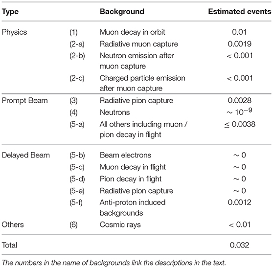
Table 4. Summary of the estimated background events for a single-event sensitivity of 3 × 10⁻¹⁵ in COMET Phase-I with a proton extinction factor of 3 × 10⁻¹¹.
4.2. Sensitivity Estimation
Figure 7 shows the estimated DIO background spectrum and μ−e conversion signal spectrum assuming 3 × 10⁻¹⁵ conversion rate. Other backgrounds are not shown in this plot, as their contributions are negligible. It is also evident that signal and DIO background separation will be clear due to enough momentum resolution of CDC.
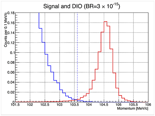
Figure 7. The momentum distributions for the reconstructed μ−e conversion signals (right solid red curve with peaking distribution) and reconstructed DIO events (left solid blue curve with decreasing distribution). The vertical scale is normalized such that the integral of the signal curve is equal to one event. This assumes a branching ratio of B(μN → eN) = 3.1 × 10⁻¹⁵.
Based on these acceptance and background estimations, the Single Event Sensitivity (SES) can be obtained by:
where is the total number of protons, is muon yield per proton obtained from simulation, fcap = 0.61 is the fraction of captured muon to the total muons on target, fgnd = 0.9 is the fraction of muon conversion to the ground state, and Aμ-e = 0.041 is the signal acceptance. The estimated SES is
With the proton beam current of 3.2 kW, the measurement requires about 1.26 × 10⁷ s, corresponding to around half year. It should be noted that the pion production rate per proton is not well understood. Therefore, the run time could be uncertain accordingly.
5. Beam Measurement Program in Phase-I and COMET Phase-II
5.1. Beam Measurement Program and StrECAL Detector
After μ−e conversion measurement is completed in COMET Phase-I, the beam measurement program in view of COMET Phase-II will follow. This measurement will utilize the prototype of StrECAL COMET Phase-II detector, that will be put instead of CyDET at the end of pion and muon transport solenoid. Those detectors will measure the pions and muons, along with other particle components, and finally, the beam profile, rate, and timing structure as a function of the energy for each kind of particle in the beam will be estimated. These information will be very useful to understand the background of Phase-II experiment, and estimation of its sensitivity. The simulations can be tuned using acquired realistic data which will provide more realistic estimation on the background. The beam power will be reduced around 1/1,000 than Phase-I running, because of limited rate capability of StrECAL detector which is actually designed for Phase-II experiment with reduced background condition after curved detector solenoid and particle momentum selection.
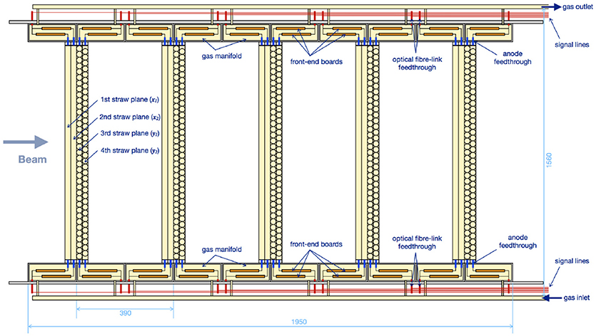
In this regard, the Phase-II detector, StrECAL is being developed along with Phase-I setup. StrECAL is composed of tracker stations using straw detectors, followed by the calorimeter array, for measuring the particle momentum and the energy, respectively. Figure 8 is the configuration of straw detector for COMET Phase-II experiment. The calorimeter array will be located at the end of the Straw detector stations (not shown in the figure).
Straw tracking system is composed of several units of single straw tracking detectors, each is composed of four layer of straws. The directions of the two and the other two layers are orthogonal in order to provide 2 dimensional hit position information. The straws are 9.75 mm diameter conducting straws, composed of metalized polyimide film of 20 μm thickness. The anode wires are 25 μm diameter gold plated Tungsten wire. The baseline choice of the gas is Argonne and Ethane (50:50) mixture. The readout boards are custom made utilizing ASD chip [41] as amplifier and DRS4 chip [42] as digitizer.
The calorimeter array is composed of around 2000 LYSO (Lutetium-Yttrium Oxyorthosilicate) crystal calorimeter module. The size of each module is 2 × 2 cm2 cross-section with the length of 12 cm corresponding to 10.5 radiation length. The calorimeter is required to have an energy resolution of better than 5% at 105 MeV and a cluster position resolution of better than 1 cm. Avalanche photodiode (APD) or silicon photomultipliers (SiPMs) are candidate as photon detector. The calorimeter arrays measure the particle energy, as well as it provides the primary trigger signal.
5.2. COMET Phase-II Experiment
The COMET Phase-II experiment is aiming at measuring the μ−e conversion with a sensitivity of O(10−17), using a proton beam of 8 GeV and 56 kW. The target sensitivity will be 100 times better than COMET Phase-I experiment. Figure 9 shows the conceptual drawing of COMET Phase-II experiment, compared with Phase-I experiment setup. In COMET Phase-I, half length 90° pion and muon transport solenoid will be used, however, full 180° curved transport solenoid followed by straight solenoid section for further pion decay will be employed in Phase-II. This will enable less pions and more muons in the beam, and finally decrease the RPC background with higher muon statistics. After muon stopping target, curved detector solenoid will be placed which provides solenoidal field as well as compensating dipole field. This solenoid system performs effectively as particle momentum selector. Therefore, the detector will observe around 60–120 MeV/c momentum ranging particles only. This removes most of low energy beam particles as well as other beam related or DIO backgrounds. The curved solenoid structure also removes background from line-of-sight neutral particles, such as photons from RMC. The full setup of StrECAL detector system will be placed in the solenoidal field to measure the momentum and energy of conversion electrons. Simulation study is ongoing for design update and starting of construction after Phase-I experiment completion. Preliminary study result shows signal efficiency of 5.7%, number of backgrounds of 0.66 events dominated by cosmic ray background, and single event sensitivity of 2.6 × 10⁻¹⁷ using 6.83 × 10²⁰ protons during 1.57 × 10⁷ s [43].
6. Summary and Prospects
The COMET experiment is a search for μ−e conversion, which is one of the most important cLFV searches. It utilizes 8 GeV proton beam from J-PARC to produce muons, which will be captured in Aluminum target for muon conversion. The muon conversion signal will be measured using cylindrical drift chamber detector in the Phase-I experiment. The estimated single event sensitivity is 3 × 10⁻¹⁵ which is 100 times improvement over the current world limit. The detector and facility construction is on schedule. Some of important parts such as muon transport solenoid and drift chamber are ready and operational. Other detector components will be commissioned and tested by the end of 2019, to be ready for the beam which will arrive subsequently. The COMET Phase-II development is also in progress, for example, the prototype StrECAL detector test is completed. The data taking of Phase-II experiment will be performed after Phase-I completion, where it will be possible to reach O(10−17) muon conversion sensitivity.
Author Contributions
The corresponding author have written this review article on behalf of COMET collaboration.
Conflict of Interest Statement
The author declares that the research was conducted in the absence of any commercial or financial relationships that could be construed as a potential conflict of interest.
Acknowledgments
The COMET collaboration thank KEK and J-PARC, Japan for their support of infrastructure and the operation of COMET. This work is supported in part by Japan Society for the Promotion of Science (JSPS) KAKENHI Grant No. 25000004; JSPS KAKENHI Grant No.JP17H06135; Belarusian Republican Foundation for Fundamental Research grant F18R-006; National Natural Science Foundation of China (NSFC) under Contracts No. 11335009 and 11475208; Research program of the Institute of High Energy Physics (IHEP) under Contract No. Y3545111U2; the State Key Laboratory of Particle Detection and Electronics of IHEP, China, under Contract No.H929420BTD; National Institute of Nuclear Physics and Particle Physics (IN2P3), France; Shota Rustaveli National Science Fund (SRNSF), Georgia; Topical Plan of Joint Institute for Nuclear Research (JINR) Research and International Cooperation project COMET #1134; Institute for Basic Science (IBS) of Republic of Korea under Project No. IBS-R017-D1-2018-a00; Russian Foundation for Basic Research Grant No. RFBR-17-02-01073; Science and Technology Facilities Council, United Kingdom; JSPS London Short Term Predoctoral Fellowship program, Daiwa Anglo-Japanese Foundation Small Grant; and Royal Society International Joint Projects Grant. Crucial computing support from all partners is gratefully acknowledged, in particular from CC-IN2P3, France; Yandex Data Factory, Russia; and GridPP, United Kingdom.
Footnotes
1. ^The μ−e conversion rate in minimally extended SM is expected to be O(200~400) times less than μ+ → e + γ rate depending on target material [25]. The μ+ → e + γ rate in minimally extended SM is estimated in Petcov [26] and Marciano and Sandra [27].
2. ^Hereafter, it is regarded to refer negative muon (μ−) when referring muon, otherwise specifically referred as positive muon (μ+).
References
1. Abramishvili R, Akhmetshin R, Anishchik V, Aoki M, Appleby RB, Arimoto Y. COMET Phase-1 Technical Design Report, KEK Report 2015-1 (2015).
2. Bertl W, Engfer R, Hermes EA, Kurz G, Kozlowski T, Kuth J, et al. A search for μ−e conversion in muonic gold. Eur Phys J. C (2006) 47:337. doi: 10.1140/epjc/s2006-02582-x
3. de Gouvea A. (Charged) lepton flavor violation. Nucl Phys B (Proc Suppl.) (2009) 188:303. doi: 10.1016/j.nuclphysbps.2009.02.071
4. Kitano R, Koike M, Okada Y. Detailed calculation of lepton flavor violating muon-electron conversion rate for various nuclei. Phys Rev. D (2002) 66:096002. doi: 10.1103/PhysRevD.66.096002
5. Crivellin A, Davidson S, Pruna GM, Signe A. Renormalisation-group improved analysis of μ → e processes in a systematic effective-field-theory approach. J High Energy Phys. (2017) 2017:117. doi: 10.1007/JHEP05(2017)117
6. Bellgardt U, Otter G, Eichler R, Felawka L, Niebuhr C, Walter HK, et al. Search for the decay μ+ → e+e−e+. Nucl Phys. B (1988) 299:1. doi: 10.1016/0550-3213(88)90462-2
7. Perrevoort AK. Searching for lepton flavour violation with the Mu3e experiment. Proc Sci. (2017) NuFact2017:105.
8. Nardi E. Z', new fermions and flavor changing processes, Constraints on E(6) models from μ → eee. Phys Rev. D (1993) 48:1240. doi: 10.1103/PhysRevD.48.1240
9. Muller DJ, Nandi S. Top flavor: a separate SU(2) for the third family. Phys Lett. (1996) B383:345. doi: 10.1016/0370-2693(96)00745-9
10. Hill CT. Topcolor assisted technicolor. Phys Lett. (1995) B345:483. doi: 10.1016/0370-2693(94)01660-5
11. Delgado A, Pomarol A, Quiros M. Electroweak and flavor physics in extensions of the standard model with large extra dimensions. J HEP (2000) 2000:30. doi: 10.1088/1126-6708/2000/01/030
12. Agashe K, Blechman AE, Petriello F. Probing the Randall-Sundrum geometric origin of flavor with lepton flavor violation. Phys Rev. (2006) D74:053011. doi: 10.1103/PhysRevD.74.053011
13. Blanke M, Buras AJ, Duling B, Poschenrieder A, Tarantino C. Charged lepton flavour violation and (g−2)μ in the littlest higgs model with T-Parity: a clear distinction from supersymmetry. J HEP (2007) 2007:13. doi: 10.1088/1126-6708/2007/05/013
14. de Carlos B, White PL. R-parity violation effects through soft supersymmetry breaking terms and the renormalization group. Phys Rev. D (1996) 54:3427. doi: 10.1103/PhysRevD.54.3427
15. Kim JE, Ko P, Lee DG. More on R-parity and lepton family number violating couplings from muon(ium) conversion, and τ and π0 decays. Phys Rev. D (1997) 56:100. doi: 10.1103/PhysRevD.56.100
16. Gabrielli E. Model independent constraints on leptoquarks from rare muon and tau lepton processes. Phys Rev. (2000) D62:055009.
17. Arnold JM, Fornal B, Wise MB. Phenomenology of scalar lepto- quarks. Phys Rev. D (2013) 88:035009. doi: 10.1103/PhysRevD.88.035009
18. Abada A, Krauss ME, Porod W, Staub F, Vicente A, Weiland C. Lepton flavor violation in low-scale seesaw models: SUSY and non-SUSY contributions. J HEP (2014) 2004:48. doi: 10.1007/JHEP11(2014)048
19. Hisano J, Tobe K. Neutrino masses, muon g-2, and lepton flavor violation in the supersymmetric seesaw model. Phys Lett B (2001) 510:197. doi: 10.1016/S0370-2693(01)00494-4
20. Arganda E, Herrero MJ, Teixeira AM. μ−e conversion in nuclei within the CMSSM seesaw: universality versus non-universality. J HEP (2007) 2007:104. doi: 10.1088/1126-6708/2007/10/104
21. Ilakovac A, Pilaftsis A. Flavor violating charged lepton decays in seesaw-type models. Nucl Phys. (1995) B437:491. doi: 10.1016/0550-3213(94)00567-X
22. Alonso R, Dhen M, Gavela MB, Hambye T. Muon conversion to electron in nuclei in type-I seesaw models. J HEP (2013) 2013:118. doi: 10.1007/JHEP01(2013)118
23. Hambye T. CLFV and the origin of neutrino masses. Nucl Phys Proc Suppl. (2014) 248–250:13. doi: 10.1016/j.nuclphysbps.2014.02.004
24. Frank M. μ−e conversion in nuclei in the left-right supersymmetric model. Eur Phys J C (2000) 17:501. doi: 10.1007/s100520000482
25. Czarnecki A, Marciano WJ, Melnikov K. Coherent muon-electron conversion in muonic atoms. AIP Conf Proc. (1998) 435:409. doi: 10.1063/1.56214
26. Petcov ST. The processes μ → eγ, μ → eeē, ν′ → νγ in the Weinberg-Salam model with neutrino mixing. Sov J Nucl Phys. (1977) 25:340.
27. Marciano WJ, Sandra AI. Exotic decays of the muon and heavy leptons in gauge theories. Phys Lett. (1977) 67B:303. doi: 10.1016/0370-2693(77)90377-X
28. Adam J, Bai X, Baldini AM, Baracchini E, Bemporad C, Boca G, et al. The MEG detector for μ+ → e+γ decay search. Eur Phys J. C (2013) 73:2365. doi: 10.1140/epjc/s10052-013-2365-2
29. Adam J, Bai X, Baldini AM, Baracchini E, Bemporad C, Boca G, et al. New constraint on the existence of the μ+ → e+γ decay. Phys Rev Lett. (2013) 110:201801. doi: 10.1103/PhysRevLett.110.201801
30. Baldini AM, Bao Y, Baracchini E, Bemporad C, Berg F, Biasotti M, et al. Search for the lepton flavour violating decay μ+ → e + γ with the full dataset of the MEG experiment. Eur Phys J C (2016) 76:434. doi: 10.1140/epjc/s10052-016-4271-x
31. Bartoszek L, Barnes E, Miller JP, Mott J, Palladino A, Quirk J, et al. Mu2e technical design report. arXiv:1501.05241 (2015).
32. Shimazaki S, Tanigui T, Uchida T, Ikeno M, Taniguchi N, Tanaka MM. Front-end electronics of the Belle II drift chamber. Nucl Instrum Methods Phys Res A (2014) 735:193. doi: 10.1016/j.nima.2013.09.050
33. Pesaresi Barros M, Marin M, Hall G, Hansen M, Iles G, Rose A, et al. The FC7 AMC for generic DAQ & control applications in CMS. J Instrum. (2015) 10:C03036. doi: 10.1088/1748-0221/10/03/C03036
34. Ritt S, Amaudruz P, Olchanski K. The MIDAS data acquisition system. In: Proceedings of the IEEE 10th Real Time Conference (1997). p. 309.
35. Agostinelli S, Allison J, Amako K, Apostolakis J, Araujo H, Arce P, et al. GEANT4: a simulation toolkit. Nucl Instrum Meth A (2003) 506:250. doi: 10.1016/S0168-9002(03)01368-8
37. Battistoni G, Muraro S, Sala PR, Cerutti F, Ferrari A, Roesler S, et al. The FLUKA code: description and benchmarking. AIP Conf. Proc. (2007) 896:31. doi: 10.1063/1.2720455
38. Niita K, Sato T, Iwase H, Nose H, Nakashima H, Sihver L, et al. PHITS: a particle and heavy ion transport code system. Radiat Meas. (2006) 41:1080. doi: 10.1016/j.radmeas.2006.07.013
39. Czarnecki A, Tormo XG, Marciano WJ. Muon decay in orbit: spectrum of high-energy electrons. Phys Rev D (2011) 84:013006. doi: 10.1103/PhysRevD.84.013006
41. Sasaki O, Yoshida M. ASD IC for the thin gap chambers in the LHC ATLAS experiment. In: 1998 IEEE Nuclear Science Symposium Conference Record. 1998 IEEE Nuclear Science Symposium and Medical Imaging Conference (Cat. No.98CH36255) Vol.1. Toronto, ON (1998). p. 440–4. doi: 10.1109/NSSMIC.1998.775179
Keywords: muon conversion, COMET, lepton flavor violation, LFV, J-PARC
Citation: Lee MJ (2018) COMET Muon Conversion Experiment in J-PARC. Front. Phys. 6:133. doi: 10.3389/fphy.2018.00133
Received: 23 July 2018; Accepted: 30 October 2018;
Published: 20 November 2018.
Edited by:
Yoshitaka Kuno, Osaka University, JapanReviewed by:
Ernesto Arganda, Instituto de Física La Plata, ArgentinaMichael Andreas Schmidt, University of New South Wales, Australia
Angela Papa, Università degli Studi di Pisa, Italy
Copyright © 2018 Lee. This is an open-access article distributed under the terms of the Creative Commons Attribution License (CC BY). The use, distribution or reproduction in other forums is permitted, provided the original author(s) and the copyright owner(s) are credited and that the original publication in this journal is cited, in accordance with accepted academic practice. No use, distribution or reproduction is permitted which does not comply with these terms.
*Correspondence: MyeongJae Lee, bXllb25namFlbGVlQGlicy5yZS5rcg==
 MyeongJae Lee