 Chaowei Xu1†
 Xiaoming Zhang2*†Kaiyang Cheng1,3Xiaobing Shang3,4Quan Li1,3
 Zeyong Wei1,3Chao Wu1,3Hongqiang Li1,3*
- 1School of Physical Science and Engineering, Tongji University, Shanghai, China
- 2College of Physics Science and Engineering Technology, Yichun University, Yichun, China
- 3Institute of Dongguan-Tongji University, Dongguan, China
- 4College of Electronic and Information, Tongji University, Shanghai, China
Parity-time (PT) symmetric photonic systems have attracted much attention due to their intriguing properties and asymmetric behaviors. In this paper, we propose a plasmonic nanoantenna with PT-symmetric potential for unidirectional scattering functionality. The studied plasmonic nanoantenna is comprised of three metallic layers separated by two dielectric layers. Such kind of system, with the same coefficient κ of loss and gain in each of the two dielectric layers, holds the characteristic of PT symmetry. We show that the unidirectional scattering is obtained for the passive structure (i.e., κ = 0), and the switching between forward and backward directionality can be achieved with a single structure by changing the excitation wavelength, when the induced electric dipole (ED) and magnetic dipole (MD) modes satisfy the first or second Kerker conditions, respectively. In addition, we find that the forward-to-backward ratio spectra can be strongly affected by the non-Hermiticity parameter κ. In particular, it is possible to reverse the radiation direction at the same wavelength in a wide spectra band by adjusting κ. Moreover, putting the nanoantennas in an array of transverse configuration can efficiently narrow the main lobe angular beam width to be <6°. These results contribute to the basic understanding of the optical properties of active-passive finite nanostructures with potential applications, and provide new ideas for the design of novel nanostructures displaying asymmetric and tunable responses.
Introduction
Surface plasmon polaritons (SPPs) refer to collective oscillations of conductive electrons at metal and dielectric interface [1]. With metallic nanostructures at the interface, these excitations couple strongly with light, giving rise to large interaction cross-sections, and enhanced near-fields [2, 3]. When the optical field couples with the SPPs in plasmonic nanostructures, some fascinating features, and applications arise, such as photo-thermal cancer therapy [4], ultra-sensitive bio-sensing [5], and improved solar energy harvesting [6], etc. However, it is well known that the intrinsic absorption of plasmonic nanostructures is usually high, especially at optical frequency, resulting in low performance efficiency [7]. Intrinsic absorption of the metallic nanostructures [8–11] can be substantially reduced with the assistance of active materials such as dye molecules, rare earth ions, or semiconductor crystals [3]. This is because the active materials can give rise to lasing or field amplification under external pumping, and transfer energy to compensate the losses of the SPPs [12–15]. Consequently, active materials enable the development of novel light-emitting devices [16, 17], such as spasers [18–20] or, more generally, plasmonic nanolasers [21–27]. It is also important to note that tuning the level of gain shall pave a path to dynamically control the response of these systems [3, 28, 29].
Recently, a new wave of interest in active materials appears in the realm of PT-symmetric systems [3, 30]. A system with PT-symmetry is comprised of active and absorptive elements which are in appropriate spatial distribution, such that the system presents a balanced gain and loss. PT-symmetry condition is directly translated into a requirement for the dielectric function of the system, ε(r) = ε*(−r), which can be achieved using active elements [3, 31, 32]. In other words, to achieve a PT-symmetric optical potential, the real part of the permittivity shall be an even function of position while its imaginary part must be an odd one. The interest in PT-symmetry of photonic systems relies on the exotic properties including, to cite some [3], asymmetric propagation [33, 34], reflection [35], scattering [36], unidirectional invisibility [37, 38], switching [39, 40], and extraordinary non-linear behaviors [41, 42]. These intriguing phenomena have been already observed in dielectric waveguides [43] and cavities [44] or photonic lattices [45, 46], among other realizations [3].
In this regard, plasmonic nanostructures with PT-symmetry have been attracting increased attention. A pioneer study has shown that the strong interaction of surface plasmons with light can be exploited to enhance the extraordinary properties arising from the PT-symmetry [3, 47]. Successive works demonstrate asymmetric behaviors in waveguides [48] and metamaterials [49, 50], transition from absorption to amplification in cavities [51] and waveguides [52], unidirectional cloaking [53], switching [54], multiplexing [55], anisotropic emission in hybrid nanoparticles [56], and giant near-field radiative heat transfer [3, 57].
In this paper, we investigate asymmetric optical response of a plasmonic nanoantenna that operates near the PT-symmetry condition. The nanoantenna is stacked with three metallic blocks and two dielectric blocks. Each of the two dielectric blocks, sandwiched by metallic ones, is either absorptive or active, respectively, with the same value of κ but in opposite sign. With such a PT-symmetric configuration, the antenna supports a highly tunable magnetic dipole (MD) that spectrally overlaps an electric dipole (ED) mode. And the tunability is primarily dependent on the variation of κ. It is also interesting to note that the interference between the MD and ED modes gives rise to superior unidirectional scattering. The side lobe level, of forward and backward radiation, can be suppressed in the cases provided that the Kerker conditions are well-satisfied. Furthermore, we show that the scattering direction of the nanoantenna strongly depends on the non-Hermiticity parameter κ. In particular, it is feasible to switch the scattering direction of the antenna at the same wavelength in a wide spectra band by adjusting κ. We also find that the beam-width of the scattered light can be further narrowed when the antenna multilayers are arranged in a chain.
Materials and Methods
For The scattered far-field for homogeneous and substrate environments can be written as [58],
where ω is the angular frequency, r is the spatial coordinate vector, μ0 = 4π·10−7 H/m is the vacuum permeability, vd = c(εd)−1/2, c is the speed of light in vacuum, εd is the relative permittivity of dielectric surrounding, r = |r| and n = r/r is the unit vector in the direction of observation, p (m) is the electric (magnetic) dipole moment, Qe (Qm) is the electric (magnetic) quadrupole tensor, and T is the tensor of the toroidal dipole moment [59].
The multipole decompositions are accomplished in both the Cartesian basis (source-representation) and the spherical basis (field-representation). The irreducible Cartesian mutipole moments are evaluated by [58].
where α, β = x, y, z, the electric current density is obtained by using Jω (r) = -iωε0(εr - εd) Eω(r), where ε0 = 8.845·10−12 F/m is the permittivity of free space, εr is the relative permittivity of particle, Eω (r) is electric field distribution. Multipole contributions show that the resonance peaks correspond to the overlap of several different multipole decomposition of the scattered field [59].
The scattering cross sections Csca are defined from far-field scattered power (I) by normalizing to the energy flux of the incident wave (Iinc). The total scattering power can be obtained by summing the energy fluxes of multipoles which are integrations of the Poynting vector over the total solid angle,
Here, ω is the angular frequency, c is the speed of light in a vacuum, the more high-order multipoles are not shown [59].
Figure 1A shows schematic of the multi-layered metal-dielectric-metal (MDM) nanoantenna. The nanoantenna is comprised of three identical gold strips, and two dielectric strips sandwiched by gold strips. Each strip has the same lengths l = 100 nm, different thicknesses (i.e., a thickness of gold strip d = 20nm and a thickness of dielectric strip t = 15 nm). The refractive index of the passive and active dielectric strip is n + iκ and n − iκ, respectively. Here the real parts of the refractive index are fixed as n = 1.44 while the non-Hermiticity parameter κ in imaginary parts is varied for different simulations. Note that regardless of the value of κ, loss and gain are always balanced in the system. The permittivity of gold is taken from Johnson and Christy [60]. For simplicity, the whole structure is assumed to be freestanding in air (ε0 = 1) [61].
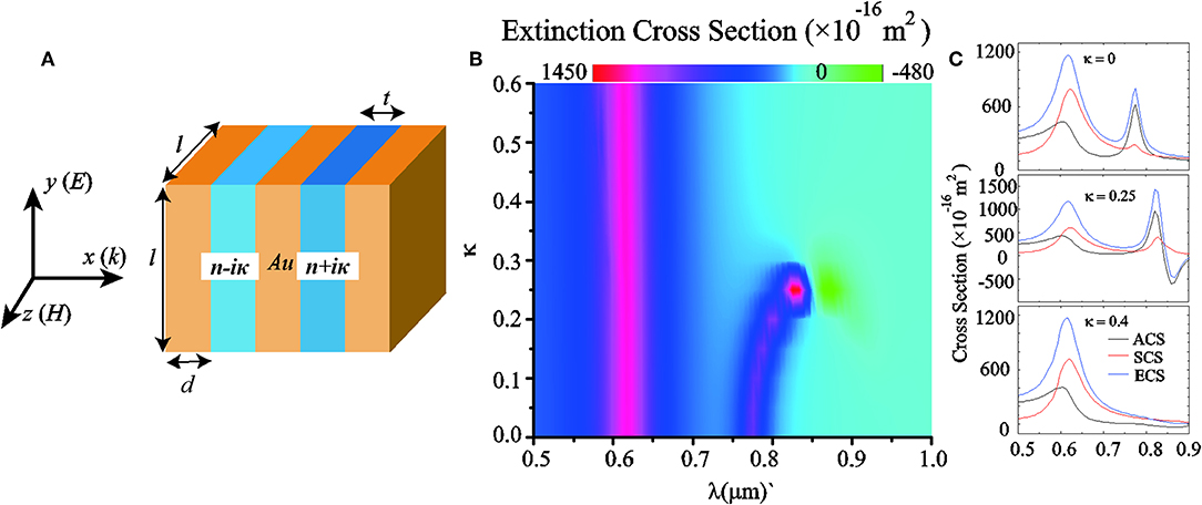
Figure 1. Optical response of the plasmonic antenna. (A) Schematic of the five layered plasmonic nanoantenna, composed of planar metallic strips separated by loss (n + iκ) and gain (n − iκ) materials. (B) Extinction cross section as a function of κ and the wavelengthλ. (C) Extinction (blue curves), scattering (red curves), and absorption (black curves) cross-sections for the same antenna of panel by calculated for three different κ: κ = 0 (top), κ = 0.25 (middle), and κ = 0.4 (bottom).
Results and Discussion
Figure 1B shows the extinction cross-section of the antenna, as a function of κ and λ. The incident plane wave, polarized in the y axis, is propagating along the x axis (see Figure 1A). All numerical calculations are performed with the finite element method (FEM) by COMSOL Multiphysics [62]. For a passive structure (i.e., κ = 0), the extinction cross-section shows two peaks corresponding to the excitations of plasmon ED and MD at shorter and longer wavelength, respectively [61]. With the increase of κ, the gain starts to compensate the loss of the system. One interesting feature is that the ED peak remains at the same wavelength of about 623 nm. Moreover, at a certain critical value (κ = 0.25 for this system), a region with negative extinction cross-section appears (see green area in Figure 1B). Beyond this critical point, the MD peak disappears and the extinction cross-section at the longer wavelength vanishes. The above behaviors are explored and demonstrated in details in Figure 1C, where the extinction (blue curves), scattering (red curves), and absorption (black curves) cross sections of the structure are plotted for three different values of κ. As anticipated, when κ = 0 (top panel), we observe two resonances that correspond to the ED and MD modes, respectively. Close to the critical point, κ = 0.25 (middle panel), the absorption cross-section (ACS) and extinction cross-section (ECS) becomes negative and predominant at the longer wavelength. With the amount of loss and gain increasing in the system, we observe the splitting of the MD. It suggests that one of the eigenmodes that is dark and not excited in the case of the passive system becomes bright when bringing loss and gain in the system. As κ is increased to 0.4 (bottom panel), the gain partially mitigates absorption losses, thus yielding a zero extinction at MD resonance. From the evolution of the MD and ED spectra based upon different κ in Figure 2, we can see that the MD mode shows strong dependence on κ, whereas the ED mode is almost unchanged. The sharp changes, occurring in the optical response of the antenna as κ approaches to the critical point, are a typical signature of a PT-symmetric system [42]. Therefore, associated with that behavior, we expect the system to exhibit an anisotropic response [3].
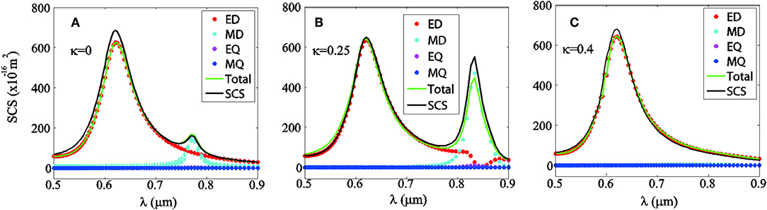
Figure 2. Evolution of the multiple moments spectra for different κ of the antenna with (A) κ = 0, (B) κ = 0.25, and (C) κ = 0.4.
To clarify the contributions of different modes, multipole decomposition including the electric dipole moment P, magnetic dipole moment M, electric quadrupole (EQ) moment Qe, and magnetic quadrupole (MQ) moment Qm can be obtained according to Khandekar et al. [57]. The radiated power of all the multipole moments sums over their contributions as:
In Figure 2, we show the multiple scattering spectra for κ = 0, κ = 0.25, and κ = 0.4. It is seen that the contributions from the induced ED and MD are significantly larger than those of EQ and MQ. Therefore, it is reasonable to neglect the high order multipole moments (EQ and MQ) that have negligible effects on the SCS for the three cases [61]. Clearly, it is seen that when κ = 0.4 the radiation from MD vanishes. Moreover, the green solid line in Figure 2 is the summation of the SCSs of the ED, MD, EQ, and MQ, which shows good agreement with the total SCS (black solid lines) obtained from the FEM simulation for the three cases, further confirming negligible contributions from other higher order modes [63].
To gain clearly understanding of the resonant dipole modes, we plot the surface charge distributions for two wavelength peak position of the SCS spectra when κ = 0 in Figure 3. Our previous work has shown that the first peak (i.e., λ = 610 nm) in this system corresponds to an electric dipole resonance in which the induced currents on the three plasmonic strips oscillate in phase [61], and the corresponding surface charge distribution is plotted in Figure 3A. The ED is induced by the metallic strips and it remains almost unchanged when varying κ, this can be confirmed in Figure 2 [58]. In order to better understand how the MD mode can be excited, the charge distribution of the other mode at λ = 778 nm is shown in Figure 3B, we can see that the forming strong circulating displacement currents in the both left two and right two metallicstrips induced the strong cavity magnetic dipole resonance mode. This kind of cavity mode is strongly affected by the material of dielectric layers (see Figure 2) [61]. Furthermore, as shown in Figures 2A,B, we can see that the ED and MD modes spectrally overlap in the spectrum and may have different radiation interferences that can shape the scattering pattern. The differential directionality (measured in decibels) of an antenna reads as follows [61, 63]:
Where θ and φ are spherical angles, and S(θ, φ) is the radiated power in the given direction θ and φ. Here, we are primarily interested in the forward-backward (FB) ratio G = DF-DB = 10 × log 10(SF/SB), where SF and SB are the far-field radiated powers in the forward and backward directions, respectively. The forward-backward ratio G allows a rough assessment of the directionality of the antennas [61]. The FB ratio G is plotted in Figure 4 as a function of wavelength λ and non-Hermiticity parameter κ. For a passive structure (i.e., κ = 0), we can see that G reaches about −30 dB at λ = 747 nm and nearly 34 dB at λ = 813 nm. Notice that positive(negative) G means that forward(backward) scattering dominates [61]. As κ increases, the gain starts to compensate the loss of the system, while both the peak and dip of Gare red-shifted and become broader. Interestingly, in the wavelength range from 807 to 885 nm, we can change the sign of Gat the same wavelength by tuning κ. Here we give two cases for λ = 835 nm and λ = 870 nm in Figures 4B,C, respectively. It is seen that for λ = 835 nm, G reaches the peak (dip) of +41 dB (−47 dB) when κ = 0.14 (κ = 0.34). Similarity, it is seen that for λ = 870 nm, G reaches the peak (dip) of +49 dB (−51 dB) when κ = 0.21 (κ = 0.3).
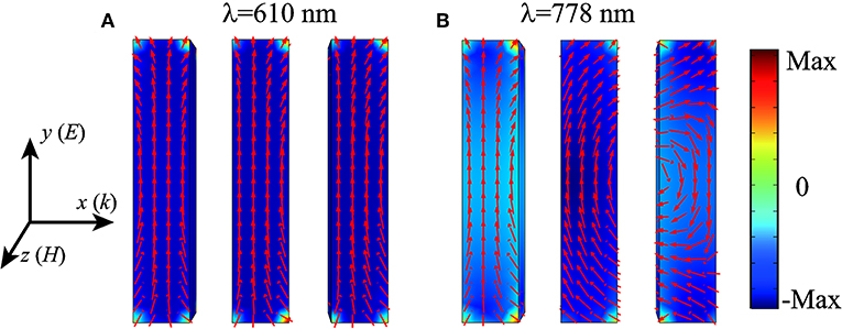
Figure 3. Surface charge distributions for the two resonant peaks [610 nm (A) and 778 nm (B)] when κ = 0 in Figure 2A.
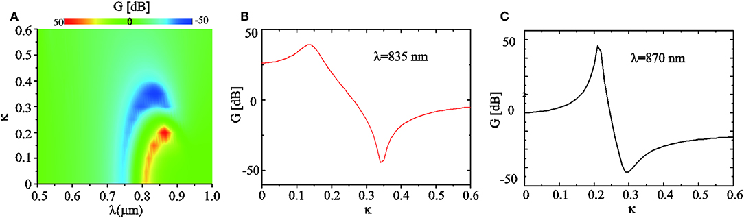
Figure 4. Unidrectional scattering produced by the PT-symmeric structures. (A) The forward to backward ratio G as a function of κ and the wavelength. (B) G as a function of κ at λ = 835nm. (C) G as a function of κ at λ = 870nm.
The scattered electric farfield resulting from the combination of such p and m are as follows:
Where p(m) is the dipole moment of the ED (MD), kis the wave vector, n = k/|k|is the unit vector in the emission direction, and r is the coordinate vector. According to Equation (10), zero forward or backward scattering requires (1) the two dipoles (ED and MD) are orthogonal to each other, (2) their radiated powers are nearly identical, and (3) the phase difference Δφ = φp − φm = 0 (forward scattering) or Δφ = ±π (backward scattering), where φp and φm are the relative phase of the induced p and m in the nanoantenna. In our case, when Δφ = φp−φm = 0 is fulfilled (i.e., the first Kerker condition) [64], most radiated power is directed to the left half space (+xdirection). Likewise, when Δφ = φp−φm = ±π (i.e., the second Kerker condition) is nearly fulfilled, scattering to the right half space (−xdirection) dominates [61]. In our system, it is reasonable to assume the ED and MD to be oriented along the corresponding vectors of the incident field. It means that the induced electric and magnetic dipole moments of the antenna in Figure 1A should be p = (0, py, 0) and m = (0, 0, mz), respectively. To demonstrate the first and second Kerker conditions can be switched at the same wavelength by adjusting κ, we take the case shown in Figure 4C (i.e., λ = 870 nm) as the example. Figure 5 shows the normalized radiated powers (left axis) and the phase difference (right axis) of the induced dipole moments py and mz as a function of the non-Hermiticity parameter κ. It is seen that at κ = 0.21 the radiated powers of py and mz have comparable amplitudes (see the dashed curve in Figure 5) and relatively small phase difference Δφ = 0.09π (see the green solid curve in Figure 5), thus the first Kerker condition is approximately reached. In a similar way, the second Kerker condition is nearly met at κ = 0.3 with Δφ = 0.94π. We note that the first (second) Kerker condition can be achieved at all the peaks (dips) of G which corresponding to the red (blue) area in Figure 4A (results not shown here).
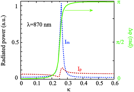
Figure 5. The normalized radiated powers of ED and MD moment and their relative phase difference Δφ for λ = 870nm.
In Figures 6A,B, we plot the 2D far-field scattering patterns in xoz plane at λ = 835 nm for κ = 0.14 and κ = 0.34, respectively. It shows that an almost complete cancellation of the radiation toward the left-half space (+x direction) and a predominated radiation toward to the right-half space (−x direction) for κ = 0.14 (see Figure 6A). In sharp contrast, for κ = 0.34, the radiated power scatters almost completely toward the −x direction (see Figure 6B) [61]. Similar features can be seen for κ = 0.21 and κ = 0.3 when λ = 870 nm as shown in Figures 6C,D. To better characterize the directivity of the scattering, we also label the main lobe angular beam-width α which corresponds to the angle for the full width at half-maximum of the differential scattering intensity [63], as shown in Figure 6. It is seen that for λ = 835 nm α is 62° when κ = 0.14 and 63° when κ = 0.34. For λ = 870 nm shown in Figures 6C,D, α is 88° when κ = 0.21 and 91° when κ = 0.3. Figure 6 further shows that the scattering direction of the antenna at a fixed wavelength can be reversed by adjusting κ.
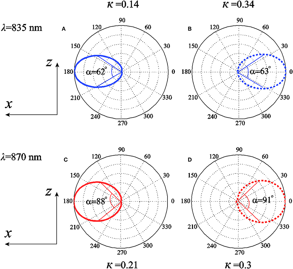
Figure 6. 2D radiation patterns in the xoz plane. (A,B) Scattering pattern with κ = 0.14 and κ = 0.34 at λ = 835nm, respectively. (C,D) Scattering pattern with κ = 0.21 and κ = 0.3 at λ = 870nm, respectively.
In order to explore more scattering properties of the PT-symmetric systems, we investigated a series of five-layer plasmonic nanoantennas. First, a five-layer plasmonic nanoantenna, composed of planar metallic strips separated by two materials with different amount of gains, n-iκ1 and n-iκ2, is simulated as shown in Supplementary Figure 1. There is no positive and negative change of unidirectivity in this system. The unidirectivity keeps positive at all values of κ1 and κ2. Secondly, a five-layer plasmonic nanoantenna, composed of planar metallic strips separated by two materials with different amount of losses, n+iκ1 and n+iκ2, is simulated as shown in Supplementary Figure 2. Similarly, there is no positive and negative change of unidirectivity and the unidirectivity keeps positive at all values of κ1 and κ2. Finally, the previous constructed PT-symmetric structure is also calculated with different loss (n+iκ1) and gain (n–iκ2) materials, as shown in Supplementary Figure 3. In the results, it is shown that the unidirectivity could switch between positive and negative with the change of κ1 and κ2. When κ1 = κ2 = κ, the results are coincident with the previous results in Figure 4. In order to investigate the presence of critical point, we describe state coalescence and power flow along the waveguide, as shown in Supplementary Figure 4.
We also studied the opposite incidence (-x direction, from right to left) in the PT-symmetric system, as shown in Supplementary Figure 5. The forward-backward ratio G results are smaller than the positive incidence results in Figure 4. The transmission and reflection properties of the PT-symmetric structure are simulated in plane wave incidence at λ = 835 nm and λ = 870 nm (see Supplementary Figure 6). The peaks(dips) of transmissivity/reflectivity ratio basically correspond to the peaks(dips) of G in Figure 4C. It is demonstrated that the positive and negative unidirectivities are related to transmission and reflection enhancements.
In Figures 7B,C, we show the scattering patterns in xoz plane by putting the antennas in a chain along y axis. The operating wavelength is λ = 870 nm and the inter-particle distance is fixed at d0 = 300 nm. Significant reduction in α is obtained with increasing number of antennas N due to the constructive far-field interferences, which is quite similar to previously reported study in high-index dielectric particle chain of longitudinal configuration [63]. The operating wavelength of λ = 870 nm can offer the best directionality with the narrowest α of 5.6° for κ = 0.21 and 5.8° for κ = 0.3 when N = 6 [63]. As a result, arranging the antennas into an array can achieve needle-like radiation [65].
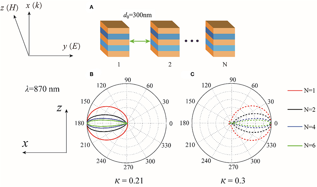
Figure 7. (A) Chain of the PT-symmetric structure with inter-particle distance d. (B,C) Scattering patterns in xoz plane by a chain such particles with N = 1, 2, 4, and 6 for κ = 0.21 and κ = 0.3 at λ = 870nm, respectively.
Considering low values of non-Hermiticity parameter, we also redesigned a five-layer plasmonic nanoantenna with the geometric parameters (l1 = 30 nm, d1 = 8 nm, t1 = 6 nm), as shown in Supplementary Figure 7. For an available gain material with the κ ≤ 0.2, the tunable unidirectivity could also be realized in designed structure. In addition, the structure parameters could be further optimized to obtain excellent performance, and we will research more about it in the following work.
Conclusions
In conclusion, we have studied the scattering properties of a multi-layered MDM plasmonic nanoantena with balanced gain and loss in the dielectric layers. We showed that the non-Hermiticity parameter has strong influences on the total cross sections and the scattering directionality of the antenna. In particular, the antenna exhibits unidirectional scattering which can be tuned by changing the non-Hermiticity parameter κ. These interesting scattering features of the antenna can be understood by the phase shifts between the electric and magnetic dipole moments induced in the asymmetric material composition. Our results are useful in designing unidirectional plasmonic nanoantennas with active materials.
Data Availability Statement
All datasets generated for this study are included in the manuscript/Supplementary Files.
Author Contributions
HL and XZ conceived the idea and supervised the whole study. XZ, CX, and KC conducted the numerical calculations and drafted the first manuscript. XZ, CX, XS, QL, KC, CW, ZW, and HL derived the theory and carried out the analysis. All authors contributed to the review of manuscript.
Conflict of Interest
The authors declare that the research was conducted in the absence of any commercial or financial relationships that could be construed as a potential conflict of interest.
Acknowledgments
This work was supported by National Natural Science Foundation of China (NSFC) (11174221, 11204218, 11404213, 11674248, 61205041, 11174057); supported by the Fundamental Research Funds for the Central Universities.
Supplementary Material
The Supplementary Material for this article can be found online at: https://www.frontiersin.org/articles/10.3389/fphy.2019.00161/full#supplementary-material
References
1. Zhang X, Xiao J, Zhang Q, Li L, Yao Y. Plasmonic TM-like cavity modes and the hybridization in multilayer metal-dielectric nanoantenna. Opt Exp. (2015) 23:16122–32. doi: 10.1364/OE.23.016122
2. Halas NJ, Lal S, Chang W, Link S, Nordlander P. Plasmons in strongly coupled metallic nanostructures. Chem Rev. (2011) 111:3913–61. doi: 10.1021/cr200061k
3. Manjavacas A. Anisotropic optical response of nanostructures with balanced gain and loss. ACS Photon. (2016) 3:1301–7. doi: 10.1021/acsphotonics.6b00274
4. O'Neal DP, Hirsch LR, Halas NJ, Payne JD, West JL. Photo-thermal tumor ablation in mice using near infrared absorbing nanoparticles. Cancer Lett. (2004) 209:171–6. doi: 10.1016/j.canlet.2004.02.004
5. Alvarez-Puebla R, Liz-Marzán LM, Abajo FJGD. Light concentration at the nanometer scale. J Phys Chem Lett. (2010) 1:2428–2434. doi: 10.1021/jz100820m
6. Atwater HA, Polman A. Plasmonics for improved photovoltaic devices. Nat Mater. (2010) 9:205–13. doi: 10.1038/nmat2629
7. Khurgin JB. How to deal with the loss in plasmonics and metamaterials. Nat Nanotechnol. (2015) 10:2–6. doi: 10.1038/nnano.2014.310
8. Nezhad M, Tetz K, Fainman Y. Gain assisted propagation of surface plasmon polaritons on planar metallic waveguides. Opt Exp. (2004) 12:4072–9. doi: 10.1364/OPEX.12.004072
9. Gather MC, Meerholz K, Danz N, Leosson K. Net optical gain in a plasmonic waveguide embedded in a fluorescent polymer. Nat Photonics. (2010) 7:457–61. doi: 10.1038/nphoton.2010.121
10. Hess O, Pendry JB, Maier SA, Oulton RF, Hamm JM, Tsakmakidis KL. Active nanoplasmonic metamaterials. Nat Mater. (2012) 11:573–84. doi: 10.1038/nmat3356
11. Zhang X, Xiao J, Zhang Q. Interaction between single nano-emitter and plasmonic disk–ring nanostructure with multiple Fano resonances. J Opt Soc Am B. (2014) 31:2193–200. doi: 10.1364/JOSAB.31.002193
12. Noginov MA, Podolskiy VA, Zhu G, Mayy M, Bahoura M, Adegoke JA, et al. Compensation of loss in propagating surface plasmon polariton by gain in adjacent dielectric medium. Opt Exp. (2008) 16:1385–92. doi: 10.1364/OE.16.001385
13. Xian J, Chen L, Niu H, Qu J, Song J. Significant field enhancements in an individual silver nanoparticle near a substrate covered with a thin gain film. Nanoscale. (2004) 6:13994–4001. doi: 10.1039/C4NR03678F
14. Song J, Xian J, Yu M, Wang D, Ye S, Niu H, et al. Ultrahigh enhancement factor by using a silver nanoshell with a gain core above a silver substrate for surface-enhanced Raman scattering at the single-molecule level. IEEE Photon J. (2015) 7:1–8. doi: 10.1109/JPHOT.2015.2481599
15. Stockman MI. Spaser action, loss compensation, and stability in plasmonic systems with gain. Phys Rev Lett. (2011)106:156802. doi: 10.1103/PhysRevLett.106.156802
16. Lozano G, Louwers DJ, Rodriguez SRK, Murai S, Jansen OTA, Verschuuren MA, et al. Plasmonics for solid state lighting:enhanced excitation and directional emission of highly efficient light sources. Light. (2013) 2:e66. doi: 10.1038/lsa.2013.22
17. Liu K, Li N, Sadana DK, Sorger VJ. Integrated nanocavity plasmon light sources for on-chip optical interconnects. ACS Photonics. (2016) 3:233–42. doi: 10.1021/acsphotonics.5b00476
18. Bergman DJ, Stockman MI. Surface plasmon amplification by stimulated emission of radiation: quantum generation of coherent surface plasmons in nanosystems. Phys Rev Lett. (2003) 90:027402. doi: 10.1103/PhysRevLett.90.027402
20. Zheludev NI, Prosvirnin SL, Papasimakis N, Fedotov VA. Lasing spaser. Nat Photonics. (2008) 2:351–4. doi: 10.1038/nphoton.2008.82
21. Noginov MA, Zhu G, Belgrave AM, Bakker R, Shalaev VM, Narimanov EE, et al. Demonstration of a spaser-based nanolaser. Nature. (2009) 460:1110–2. doi: 10.1038/nature08318
22. Oulton RF, Sorger VJ, Zentgraf T, Ma RM, Gladden C, Dai L, et al. Plasmon lasers at deep subwavelength scale. Nature. (2009) 461:629–32. doi: 10.1038/nature08364
23. Sorger VJ, Zhang X. Spotlight on plasmon lasers. Science. (2011) 333:709–10. doi: 10.1126/science.1204862
24. Berini P, Leon ID. Surface plasmon-polariton amplifiers and lasers. Nat Photonics. (2012) 6:16–24. doi: 10.1038/nphoton.2011.285
25. Zhou W, Dridi M, Suh JY, Kim CH, Co DT, Wasielewski MR, et al. Lasing action in strongly coupled plasmonic nanocavity arrays. Nat Nanotechnol. (2013) 8:506–11. doi: 10.1038/nnano.2013.99
26. Yang A, Odom TW. Breakthroughs in photonics 2014: advances in plasmonic nanolasers. IEEE Photonics J. (2015) 7:1–6. doi: 10.1109/JPHOT.2015.2413773
27. Ho J, Tatebayashi J, Sergent S, Fong CF, Iwamoto S, Arakawa Y. Low-threshold near-infrared GaAs-AlGaAs core-shell nanowire plasmon laser. ACS Photonics. (2015) 2:165–71. doi: 10.1021/ph5003945
28. Krasavin AV, Vo TP, Dickson W, Bolger PM, Zayats AV. All-plasmonic modulation via stimulated emission of copropagating surface plasmon polaritons on a substrate with gain. Nano Lett. (2011) 11:2231–35. doi: 10.1021/nl200255t
29. Zhu W, Premaratne M, Gunapala SD, Agrawal GP, Stockman MI. Quasi-static analysis of controllable optical crosssections of a layered nanoparticle with a sandwiched gain layer. J Opt. (2014) 16:075003. doi: 10.1088/2040-8978/16/7/075003
30. Bender CM, Boettcher S. Real spectra in non-hermitian hamiltonians having PT symmetry. Phys Rev Lett. (1998) 80:5243–6. doi: 10.1103/PhysRevLett.80.5243
31. El-Ganainy R, Makris KG, Christodoulides DN, Musslimani ZH. Theory of coupled optical PT-symmetric structures. Opt Lett. (2007) 32:2632–4. doi: 10.1364/OL.32.002632
32. Klaiman S, Günther U, Moiseyev N. Visualization of branch points in PT-symmetric waveguides. Phys Rev Lett. (2008) 101:080402. doi: 10.1103/PhysRevLett.101.080402
33. Longhi S. Bloch oscillations in complex crystals with PT symmetry. Phys Rev Lett. (2009) 103:123601. doi: 10.1103/PhysRevLett.103.123601
34. Ruter CE, Makris KG, El-Ganainy R, Christodoulides DN, Segev M, Kip D. Observation of parity-time symmetry in optics. Nat Phys. (2010) 6:192–5. doi: 10.1038/nphys1515
35. Kulishov M, Laniel JM, Bélanger N, Azaña N, Plant DV. Nonreciprocal waveguide Bragg gratings. Opt Exp. (2005) 13:3068–78. doi: 10.1364/OPEX.13.003068
36. Miri MA, Eftekhar MA, Facao M, Abouraddy AF, Bakry A, Razvi MAN, et al. Scattering properties of PT-symmetric objects. J Opt. (2016) 18:075104. doi: 10.1088/2040-8978/18/7/075104
37. Lin Z, Ramezani H, Eichelkraut T, Kottos T, Cao H, Christodoulides DN. Unidirectional invisibility induced by PT symmetric periodic structures. Phys Rev Lett. (2011) 106:213901. doi: 10.1103/PhysRevLett.106.213901
38. Longhi S. Invisibility in PT-symmetric complex crystals. J Phys A. (2011) 44:2813–21. doi: 10.1088/1751-8113/44/48/485302
39. Lupu A, Benisty H, Degiron A. Using optical PT-symmetry for switching applications. Phot Nano Fundam Appl. (2014) 12:305–11. doi: 10.1016/j.photonics.2014.05.003
40. Rivolta NXA, Maes B. Diffractive switching by interference in a tailored PT-symmetric grating. J Opt Soc Am. (2015) 32:1330–7. doi: 10.1364/JOSAB.32.001330
41. Miroshsnichenko AE, Malomed BA, Kivshar YS. Nonlinearly PT-symmetric systems: spontaneous symmetry breaking and transmission resonances. Phys Rev. (2011) 84:911–6. doi: 10.1103/PhysRevA.84.012123
42. Guo A, Salamo GJ, Duchesne D, Morandotti R, Volatier-Ravat M, Aimez V, et al. Observation of PT-symmetry breaking in complex optical potentials. Phys Rev Lett. (2009) 103:093902. doi: 10.1103/PhysRevLett.103.093902
43. Jia Y, Yan Y, Kesava SV, Gomez ED, Giebink NC. Passive parity-time symmetry in organic thin film waveguides. ACS Photonics. (2015) 2:319–25. doi: 10.1021/ph500459j
44. Peng B, Özdemir SK, Lei F, Monifi F, Gianfreda M, Long GL, et al. Parity-timesymmetric whispering-gallery microcavities. Nat Phys. (2014) 10:394–8. doi: 10.1038/nphys2927
45. Regensburger A, Bersch C, Miri MA, Onishchukov G, Christodoulides DN, Peschel U. Parity-time synthetic photonic lattices. Nature. (2012) 488:167–71. doi: 10.1038/nature11298
46. Wimmer M, Regensburger A, Miri MA, Bersch C, Christodoulides DN, Peschel U. Observation of optical solitons in PT-symmetric lattices. Nat Commun. (2015) 6:394–8. doi: 10.1038/ncomms8782
47. Benisty H, Degiron A, Lupu A, Lustrac AD, Chénais S, Forget S, et al. Implementation of PT symmetric devices using plasmonics:principle and applications. Opt Exp. (2011) 19:18004–19. doi: 10.1364/OE.19.018004
48. Alaeian H, Dionne JA. Non-hermitian nanophotonic and plasmonic waveguides. Phys Rev B. (2014) 89:188–92. doi: 10.1103/PhysRevB.89.075136
49. Alaeian H, Dionne JA. Parity-time-symmetric plasmonic metamaterials. Phys Rev A. (2014) 89:429–35. doi: 10.1103/PhysRevA.89.033829
50. Alaeian H, Dionne JA. Controlling electric, magnetic, and chiral dipolar emission with PT-symmetric potentials. Phys Rev B. (2015) 91:245108. doi: 10.1103/PhysRevB.91.245108
51. Baum B, Alaeian H, Dionne JA. A parity-time symmetric coherent plasmonic absorber-amplifier. J Appl Phys. (2015) 117:063106. doi: 10.1063/1.4907871
52. Mattheakis M, Oikonomou T, Molina MI, Tsironis GP. Phase transition in PT symmetric active plasmonic systems. IEEE J Sel Top Quant Electron. (2016) 22:76–81. doi: 10.1109/JSTQE.2015.2490018
53. Sounas DL, Fleury R, Alù A. Unidirectional cloaking based on metasurfaces with balanced loss and gain. Phys Rev Appl. (2015) 4:014005. doi: 10.1103/PhysRevApplied.4.014005
54. Lupu A, Benisty H, Degiron A. Switching using PT symmetry in plasmonic systems: positive role of the losses. Opt Exp. (2013) 21:21651–68. doi: 10.1364/OE.21.021651
55. Alaeian H, Baum B, Jankovic V, Lawrence M, Dionne JA. Towards nanoscale multiplexing with parity-time symmetric plasmonic coaxial waveguides. Phys Rev B. (2016) 93:205439. doi: 10.1103/PhysRevB.93.205439
56. Jin W, Khandekar C, Pick A, Polimeridis AG, Rodriguez AW. Amplified and directional spontaneous emission from arbitrary composite bodies: a self-consistent treatment of Purcell effect below threshold. Phys Rev B. (2016) 93:433–46. doi: 10.1103/PhysRevB.93.125415
57. Khandekar C, Jin W, Miller OD, Pick A, Rodriguez AW. Giant frequency-selective near-field energy transfer in active-passive structures. Phys Rev B. (2016) 94:115402. doi: 10.1103/PhysRevB.94.115402
58. Alaee R, Rockstuhl C, Fernandez-Corbaton I. An electromagnetic multipole expansion beyond the long-wavelength approximation. Opt Commun. (2018) 407:17–21. doi: 10.1016/j.optcom.2017.08.064
59. Xu C, Cheng K, Li Q, Shang X, Wu C, Wei Z, et al. The dual-frequency zero-backward scattering realized in a hybrid metallo-dielectric nanoantenna. AIP Adv. (2019) 9:075121. doi: 10.1063/1.5099533
60. Johnson PB, Christy RW. Optical constants of the noble metals. Phys Rev B. (1972) 6:4370–9. doi: 10.1103/PhysRevB.6.4370
61. Zhang X, Xiao J, Zhang Q, Qin F, Cai X, Ye F. Dual-band unidirectional emission in a multilayered metal–dielectric nanoantenna. ACS Omega. (2017) 2:774–83. doi: 10.1021/acsomega.7b00121
62. Available, online at: http://www.comsol.com (accessed July 01, 2019).
63. Zhang X, Zhang Q, Zeng S, Liu Z, Xiao J. Dual-band unidirectional forward scattering with all-dielectric hollow nanodisk in the visible. Opt Lett. (2018) 43:1275–8. doi: 10.1364/OL.43.001275
64. Kerker M, Wang DS, Giles CL. Electromagnetic scattering by magnetic particles. J Opt Soc Am B. (1983) 73:765–7. doi: 10.1364/JOSA.73.000765
Keywords: optical nanoantenna, unidirectional scattering, metallic and dielectric hybrid, parity-time symmetric, Kerker condition, tunable
Citation: Xu C, Zhang X, Cheng K, Shang X, Li Q, Wei Z, Wu C and Li H (2019) Tunable Unidirectivity of Metal-Dielectric-Metal Plasmonic Nanoantennas With PT-Symmetric Potentials. Front. Phys. 7:161. doi: 10.3389/fphy.2019.00161
Received: 16 July 2019; Accepted: 04 October 2019;
Published: 18 October 2019.
Edited by:
Yuancheng Fan, Northwestern Polytechnical University, ChinaReviewed by:
Zhengyong Song, Xiamen University, ChinaYihang Chen, South China Normal University, China
Tianyue Zhang, Jinan University, China
Copyright © 2019 Xu, Zhang, Cheng, Shang, Li, Wei, Wu and Li. This is an open-access article distributed under the terms of the Creative Commons Attribution License (CC BY). The use, distribution or reproduction in other forums is permitted, provided the original author(s) and the copyright owner(s) are credited and that the original publication in this journal is cited, in accordance with accepted academic practice. No use, distribution or reproduction is permitted which does not comply with these terms.
*Correspondence: Xiaoming Zhang, emhhbmd4bTg1NTVAMTYzLmNvbQ==; Hongqiang Li, aHFsZWVAdG9uZ2ppLmVkdS5jbg==
†These authors have contributed equally to this work