- 1R&D Department, Sordina IORT Technologies, Aprilia, Italy
- 2U.O. Fisica Sanitaria, Azienda Universitaria Ospedaliera Pisana, Pisa, Italy
Since Favaudon's paper of 2014, there has been an increasing interest in FLASH radiotherapy. The FLASH modality could represent a breakthrough in radiation oncology; nevertheless, it brings new scientific and technological challenges. Currently, one of the main limits the scientific community has to cope with is the lack of a common technological platform to experiment with. Considering this framework, the possibility of readapting existing linac platforms to produce a FLASH beam is particularly attractive and different attempts have been already made. The purpose of this article is to illustrate how it is possible to transform a dedicated Intra Operative Radio Therapy (IORT) mobile linac into a FLASH research machine. Compared to the modification required by a standard medical linac, such transformation is easier, does not affect the machine settings and can be rapidly performed by the final user. NOVAC 7 is an IORT linac which can reach a maximum dose-per-pulse up to 13 cGy/pulse (average dose rate 39 Gy/min); such dose rate can be significantly increased by modifying the collimation system.
Four different Source Surface Distance (SSD) can be obtained:
- Clinical reference configuration;
- Upper applicator only (SSD 50 cm);
- Monitor chambers housing only (SSD 7 cm);
- Dismounted monitor chambers (SSD 1.6 cm).
The fourth configuration allows reaching values of dose-per-pulse up to around 18 Gy/pulse and dose rates up to around 500 Gy/s, at a Pulse Repetition Frequency (PRF) of 30 Hz. The other three configurations can be obtained without using any tool and without changing NOVAC settings, until reaching a FLASH dose rate in the third configuration. For FLASH configurations, relative and absolute dosimetric characterization of the beam were performed using radiochromic films EBT3. NOVAC7 transformed in FLASH mode can be used both for dosimetric testing and characterization of detectors and for radiobiological studies on cells and organoids, offering a wide range of dose-per-pulse, from 3 cGy/pulse up to 18 Gy/pulse; dose rates correspondingly change from 3 cGy/s up to 540 Gy/s.
Introduction
The FLASH effect in radiotherapy is a radiobiological effect characterized by a loss of radiobiological effectiveness (RBE) on healthy tissue and an unaltered therapeutic efficacy on tumor tissue; this effect is obtained by delivering the entire therapeutic dose in a very short time, <100 ms with a dose rate above 40 Gy/s [1, 2]. The experimental evidences of the FLASH effect were obtained in vivo, using 4–6 MeV energy electron beams, and the robustness of these results are validated by the fact that they were reproduced in various animal models (mice, rat, zebrafish, pig, cats), in various organs (lung, skin, gut, brain) and by various radiobiology researchers [1–8]. These evidences aroused considerable interest in the radiotherapy community, due to the possible clinical implications [9, 10].
However, for a possible clinical use of the FLASH effect, several issues must be addressed and understood. The radiobiological mechanism underlying the FLASH effect is still unknown: oxygen consumption has been proposed as a possible solution but other works highlighted how this mechanism, probably, cannot be considered the only one [11–15].
Additionally, the dependence of the FLASH effect on some parameters characterizing the radiation beam are not fully known: only the dependences on the average dose-rate and on the duration of the entire irradiation have been clearly observed so far. The role of dose-per-pulse, instantaneous dose-per-pulse (i.e., dose-per-pulse divided by pulse duration), pulse duration and frequency still remain to be entirely understood [1–3, 9].
Finally, the dosimetric problems related to the response of the on-line dosimeters to these dose-per-pulse values (saturation problems) are important and completely new to scientific community; this aspect causes difficulties in monitoring the stability of the beam output and in the accuracy of the dosimetric measurements. Even though many issues related to FLASH remain to be understood, such effect was observed only for average dose rates above 40 Gy/s. In the following, “FLASH dose rate” or “FLASH beam” will indicate beams with average dose rate above such threshold.
Because of this scenario, it would be important to increase the number of centers where a technology capable of delivering FLASH beam is available and where researchers can study the FLASH mechanisms. Up to now, all experimental data have been obtained either by using re-adapted standard medical linac [16] or using industrial machines [17–19].
This work shows how an accelerator dedicated to IORT (Novac7, SIT, Aprilia, Italy) can be set up to obtain different dose-per-pulse regimes and, consequently, dose-rates; in particular, two of these configurations allow to obtain FLASH beams. Such configurations were characterized by means of Gafchromic EBT3 films [20]. EBT3 were chosen because of their excellent spatial resolution, dose-rate (dose-per-pulse) independence [21–24] and energy independence for photon and electron beams above hundreds of keV [21, 25].
Radiochromic films [20] provide absolute measurements of absorbed dose to water after conversion of the film response by means of an accurate calibration procedure to be determined for any specific radiochromic film dosimetry system, which consists in the combination of the film model and the densitometer, usually a flat-bed scanner, together.
Few studies investigated the dose-rate and dose-per-pulse dependence of radiochromic films [21, 22, 24]; however they all agree in reporting small or negligible dependence in their response with respect to both variables. At the dose-rate values of conventional clinical linacs, with a dose-per-pulse up to 1 × 10⁻³ Gy/pulse, Borca et al. [21] reported, for EBT3 radiochromic film, a dose-rate dependence in the range of 0.1–0.6 Gy/min within 1% for 6 and 15 MV photon beams. Jaccard et al. [22] reported, for conventional linac electron beams of 4, 8, and 12 MeV and EBT3, negligible variation in the range of 0.6–4.4 Gy/min.
Karsch et al. [23] reported, for a 20 MeV electron beam (5 ps pulse width) from the superconductive linear accelerator ELBE, a EBT radiochromic film dependence with respect to the dose-per-pulse of 2% up to about 2 × 10⁻² Gy/pulse and within 5% up to about 7.5 × 10⁻² Gy/pulse.
Jaccard et al. [22] also investigated the usability of Gafchromic EBT3 as reference dosimeters for an Oriatron eRT6 electron linac and concluded that EBT3 films are dose-per-pulse independent between about 4 × 10⁻³ Gy/pulse and 18 Gy/pulse.
Dosimetric and geometric properties of the beams obtained in the two FLASH NOVAC configurations have been evaluated in terms of dose to the build-up, dose at different depths and transversal dose profiles. These results can be useful to all NOVAC7 users, to design radiobiological experiments and/or study the response of the various dosimeters to FLASH dose-rate values. It is interesting to remind that, before the FLASH promises attracted the attention of scientific community, IORT linacs represented a challenge both from the dosimetric [26–31] and radiobiological point of view [32].
Materials and Methods
Radiochromic Films Calibration
For calibration purposes, Gafchromic EBT3 film samples of 5 × 5 cm2 were irradiated using a Varian Clinac DHX-S (Varian Medical Systems, Palo Alto, CA), with a 6 MeV electron beam. The electron beam was previously calibrated in water, following the IAEA TRS 398 protocol guidelines [33] using a Roos reference chamber [34] at SSD = 100 cm and an applicator of 20 × 20 cm2. The films were irradiated in the same set-up except for the material, a Plastic Water® phantom, at the equivalent zref depth in Plastic Water®, calculated as suggested by the IAEA TRS 398 protocol [33]. In order to obtain a calibration curve, the films were exposed, as described before, in a dose range from 2 to 20 Gy, with steps of 2 Gy. The post irradiation readings were made after 48 h. A black cardboard template was fitted into the scanner to ensure the reproducibility of the film positioning on the central location of the scan surface. The films were scanned after a 15 min warm-up time of the flatbed scanner and 3 empty scans to stabilize it. Films were acquired in transmission mode with all the image enhancement filters turned off, with a resolution of 127 dpi and at 48-bit RGB (Red, Green, Blue, 16 bits per channel). All of them were scanned in portrait orientation, i.e., the side of the 5 × 5 cm2 film sample corresponding to the long edge of the original film was positioned along the scanning direction. The images were saved in TIFF format.
A 2D Wiener filter was applied to both pre- and post-irradiation images, as suggested in [35]. The aforementioned protocol was used to obtain for each film sample the average net optical density , which is the difference between the irradiated and unirradiated optical density, over five 6 × 6 mm2 ROI (Region of Interest) positioned around the center of the radiation field. For each film sample the absorbed dose to water, D, measured with the ionization chamber, was plotted vs. the corresponding average for the Red channel. The calibration curve was determined by fitting the experimental data through the following equation:
where a, b, and n are the fitting parameters. All the analysis was performed using home-made scripts in MATLAB R2018a environment (MathWorks, Natick, MA, USA). The dose curves fitting procedure was performed in two steps, following the method described in [35], which suggested to fix the parameter n after the first procedure to reduce the fitting uncertainty. Hence, once fixed n, a second fitting procedure was carried out, obtaining new values for the parameters a and b with their corresponding uncertainties.
NOVAC7
FLASH irradiations were performed using the IORT NOVAC7 (SIT, Aprilia, Italy) accelerator [36].
NOVAC7 provides four nominal electron energies (3, 5, 7, and 9 MeV) and the electron beam collimation system is purely passive; NOVAC7 does not use any scattering foil for beam broadening. The collimation system consists of polymethylmethacrylate (PMMA) cylindrical applicators that can be directly attached to the radiant head. The applicator is made of two parts: an upper part called applicator holder or upper applicator—directly mounted to the radiant head- and the terminal part called terminal applicator, which is connected to the upper applicator by means of a ring nut. The PMMA wall of the applicator is 5 mm thick, the internal diameter ranges from 4 to 10 cm and the very end of the terminal can be flat or beveled. The length of the applicators determines the SSD, which is 100 cm for the reference applicator with a diameter of 10 and 80 cm for the others. Thanks to this relatively simple architecture, it is possible to obtain several collimation configurations (Figure 1). Every configuration lead to a different SSD and, consequently, to a different resulting dose-per-pulse. The measurements were performed using the nominal energy of 7 MeV, which is the most used in the clinical practice and the closest to the electron energies for which the experimental FLASH effects were highlighted.
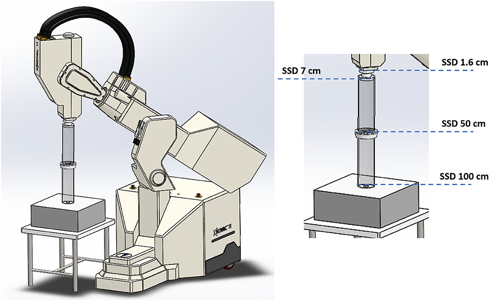
Figure 1. Four collimation configurations obtained acting on Novac7 collimation system architecture.
It is well worth underlying that, in general, the average dose-rate DR generated by a pulsed electron beam is directly proportional to the dose-per-pulse Dp
where PRF is the pulse repetition frequency. The instantaneous dose rate IDR (or dose rate within pulse) is obtained dividing the dose-per-pulse Dp by the pulse length Δt. For the NOVAC Δt is about 2.5 μs, its IDR can be easily calculated as
Due to the relatively low PRF (5 Hz in Clinical mode, up to 30 Hz in Service mode), dose rate is not extremely high; nevertheless, the dose-per-pulse can reach very high values.
Measurements
The different setups were obtained as follows:
(1) Clinical reference configuration: (SSD 100 cm);
(2) Upper applicator connected to the monitor chambers housing (SSD 50 cm);
(3) Monitor chambers housing only (SSD 7 cm);
(4) Dismounted monitor chambers (SSD 1.6 cm).
NOVAC 7 monitor chambers behavior remains unaffected in configurations 1, 2, and 3 (short term stability better than 0.5%); in the fourth configuration instead, NOVAC can be operated only setting the number of pulses to be delivered. In Figure 2 such configurations, together with the possible maximum achievable dose-rates, are detailed. For all four configurations, the maximum dose-per-pulse value on the central axis of the beam in equivalent water phantom was measured, while for the last two configurations, being the only ones reaching FLASH values (called FLASH1 and FLASH2, corresponding to SSD of 7 and 1.6 cm, respectively), depth-dose measurements and dose profiles were also performed. The experimental setup used to characterize the beam in these two operating modes is shown in Figure 3. In order to characterize the beam in terms of dose-per-pulse and depth-dose curve, the radiochromic films were inserted perpendicularly to the electron-beam axis between Plastic Water® slabs at different depths for the first (1) and second (2) FLASH regimen, as reported in Table 1. Then, the accelerator head was put in contact with the first slab (see Figure 3, on the right).
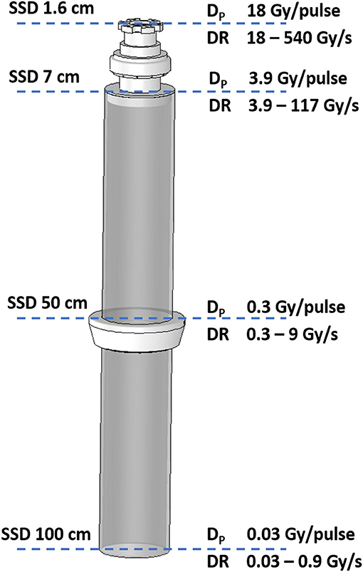
Figure 2. Detail of collimator with the indications of the four SSD and the corresponding possible maximum achievable dose-per-pulse (Dp) and dose rate (DR) for the 7 MeV e-beam.
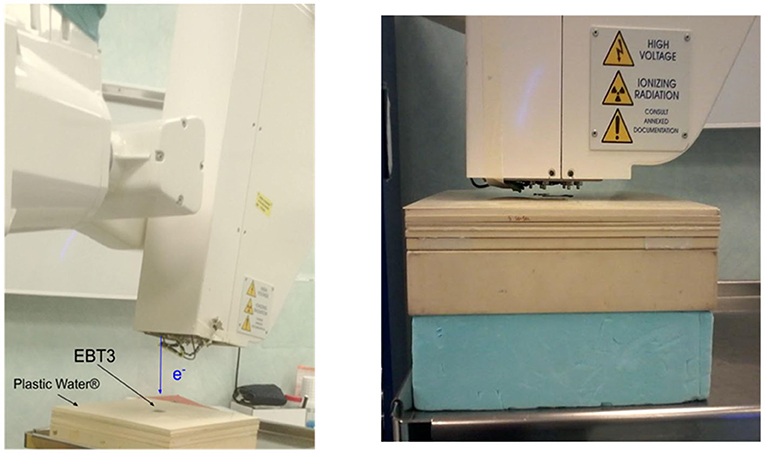
Figure 3. Schematic view of the experimental set-up. On the left, the set-up with the accelerator head. On the right, the configuration during the irradiation (notice the proximity between beam window exit and the Plastic Water® slabs).
Given the short distance between the first Plastic Water® layer and the beam exit window, it was possible to center the films manually with great accuracy. Moreover, the instantaneous darkening after the irradiation provided the possibility of an immediate check of the correct positioning.
The dimensions of films (5 × 5 cm2) were suitable to include all the useful beam considering its broadening in depth. All the irradiations were performed using the nominal energy 7 MeV and delivering, for each point of measure, a total dose between 10 and 20 Gy. The total number of pulses delivered was changed according to the specific set-up, ranging from 400 pulses in clinical configuration down to just one pulse in FLASH 2 mode.
The radiochromic films irradiated with FLASH beams were read after 48 h through the same reading procedure adopted for their calibration.
To determine the amount of dose delivered in each image pixel of the films, the netODi for the i-th pixel was calculated [according to Equation (1)], then it was converted in dose using the calibration curve. Thus, the distribution of dose in the transverse plane was obtained at each depth for each FLASH condition.
A series of dose profiles were extracted from the above-mentioned dose maps for each measurement depth. The central region of each map was considered and the dose values of eight consecutive horizontal/vertical lines were averaged pixel by pixel to obtain the final dose profiles along the horizontal/vertical direction (thereinafter x and y).
To provide an estimation of the beam size, the Full Width at Half Maximum (FWHM) of the curves was used. All the profiles were fitted with a Gaussian function (Gaussian fits were performed by using Matlab R2018a fit tools), as shown in Figures 6, 7.
The beam profiles were exploited to choose the ROI size for dose calculation as a compromise between two conflicting requirements: a larger ROI size allows to reduce the statistical error, while a smaller ROI increases the dose distribution uniformity. To preserve such advantages by minimizing the above-mentioned trade-off, ROI sizes variable with depth were adopted. In particular, ROI size was chosen in order to guarantee dose values fluctuation lower than 2% inside. The average dose delivered inside these ROIs is used to calculate the corresponding dose-per-pulse value.
Depth-dose curve was obtained from the depth-dose distribution and the depth corresponding to the 50% of the maximum absorbed dose, R50, was evaluated.
Results
Dose-Response Curves for EBT3 Calibration
The dose values plotted as function of the netOD are shown in Figure 4, together with the fitting curve calculated with the parametrization given in Equation (1). The corresponding fitting parameters are a = 14.07 ± 0.04 Gy, b = 52 ± 2 Gy, and n = 3.45.
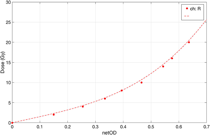
Figure 4. Dose-response curve of EBT3 under conventional dose-rate irradiation with 6 MeV electrons in the range 0–20 Gy. The fit curve is plotted as dotted line.
FLASH Beams Characterization
Figure 5 shows the relative dose distributions measured in the two operating modes: FLASH beam 1 on the left and FLASH beam 2 on the right. The dose distribution measured on the film is not uniform in the radial direction.
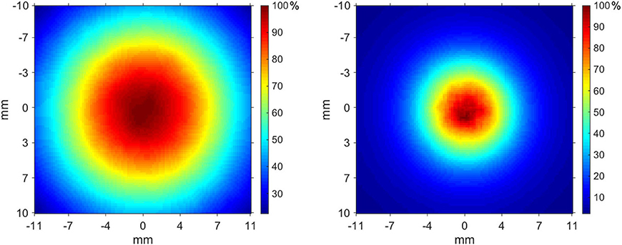
Figure 5. Transverse dose distribution measured at 6 mm in Plastic Water® slabs—FLASH beam 1 (left), FLASH beam 2 (right).
The profiles measured at each depth are presented in Figure 6 (FLASH beam 1) and in Figure 7 (FLASH beam 2). As confirmed by R2 values reported in the figures, the profiles are well-approximated by a Gaussian curve except for the FLASH beam 2 profiles close to phantom surface (R2 < 0.99).
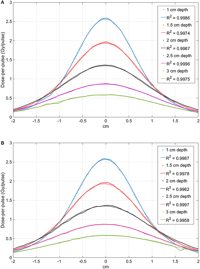
Figure 6. Comparison between the profiles obtained at different depth with the FLASH beam 1. Image (A) shows the X-profiles while image (B) shows the Y-profiles. The superimposed continuous lines show the fit with a Gaussian function; R2 values are reported for each curve.
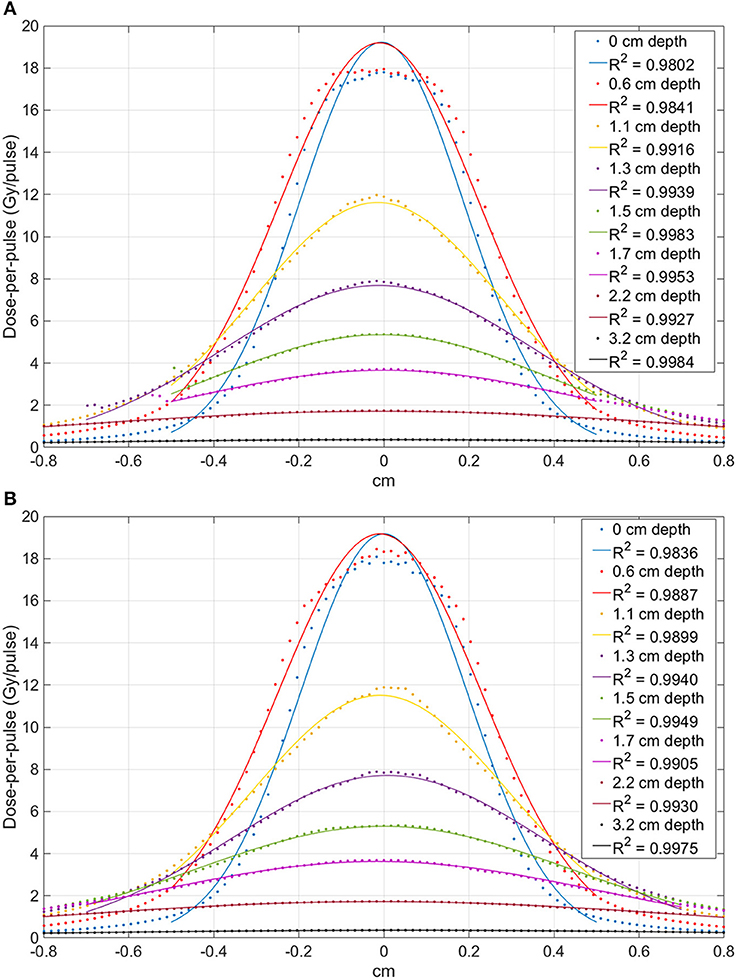
Figure 7. Comparison between the profiles obtained at different depth with the FLASH beam 2. Image (A) shows the X-profiles while image (B) shows the Y-profiles. The superimposed continuous lines show the fit with a Gaussian function; R2 values are reported for each curve.
The beam profiles along the x and y axes are reported in Figures 6, 7 as function of the depths. The beam becomes significantly narrower when removing the monitor chamber, providing the smallest FWHM (Figure 7). Furthermore, the beam size increases with increasing depth in both irradiation modes, although the dependency from the measurement depth is not the same for the two cases (Figure 8).
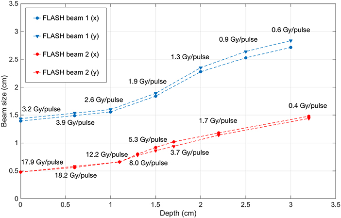
Figure 8. Beam FWHM measured at different depths inside solid water with FLASH beam 1 (blue) and FLASH beam 2 (red), with the corresponding dose-per-pulse.
The different width of the beam in the two configurations is due to both the different distance and the presence/absence of the two monitor chambers. A NOVAC7 monitor chamber basically consists of two aluminum electrodes, each 0.02 mm thick behaving as a thin scattering element [28].
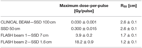
The depth-dose distributions measured in the Plastic Water® phantom are shown in Figure 9 for the two FLASH regimens. The maximum dose-per-pulse values and their relative errors obtained from Figure 9 are presented in Table 2. The highest dose-per-pulse value is reached without monitor chamber (FLASH beam 2). In Table 2, the R50 calculated from the dose deposition curves are presented.
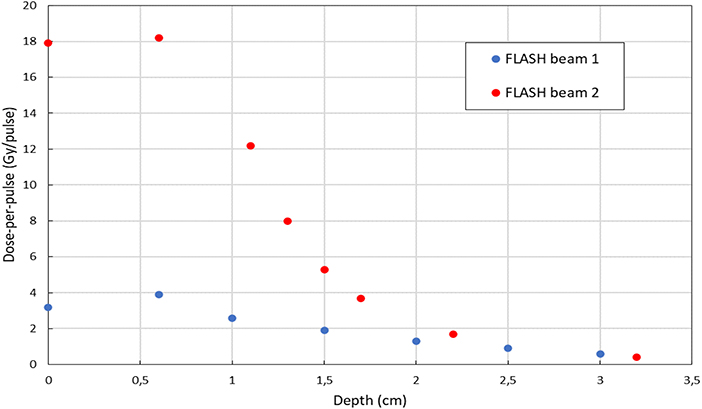
Figure 9. Depth-dose distribution of electrons measured in a plastic phantom with EBT3 in FLASH beam 1 mode (blue) and FLASH beam 2 mode (red).
The uncertainty associated to dose measurements is 3% at SSD 100 cm, where the dose is measured by means of ionization chamber [26–28, 31] and 5% for all other points, where EBT3 are used. EBT3 tends to underestimate dose deposition when beam energy is below few tenths of keV [25]; therefore a higher uncertainty affects surface dose measurements. However, due to the very limited range of such electrons, this effect can be considered negligible beyond 2–3 mm, and, consequently, it does not affect build-up measurements reported in Table 2.
Discussion and Conclusion
Currently, the two centers that published most of the FLASH results, Marie Curie Institute in Paris and University of Lausanne, adopted Kinetron and Oriatron, respectively, linacs originally designed for industrial use [1–3, 5, 7–9, 17–19].
Another possible solution is described in [16], where a procedure for modifying a standard clinical linac in order to get a FLASH beam is illustrated.
Several research groups are working to build a dedicated FLASH machine; not only electron based machines [37] are considered, but also linacs for X-ray [38] or proton accelerators [39]. The concept of PHASER [38] is particularly interesting, but its feasibility remains extremely challenging both from the clinical and the technological point of view. Clinical difficulties related to “FLASH IMRT” are discussed in [40]; furthermore, the generation of a X-ray beam capable of reaching FLASH dose rate requires at least four times the electron current needed for linac working in electron mode [refer to NIST data [41] for Bremsstrahlung efficiency]. On the other hand, the effective implementation of FLASH with proton is feasible, even though it also poses several technological issues. However, the maximum dose rates achievable are significantly lower respect to electron based linacs, and many issues, in particular those related to real time beam monitoring, remain unsolved (Jolly et al. unpublished).
In this context, the possibility of expanding the number of researchers who can experiment with a FLASH beam may represent a crucial element for speeding up and validating the understanding of all phenomena involved.
This work described a procedure for transforming NOVAC, an IORT linac, into a FLASH machine: two out of four configurations identified reach the FLASH region (dose rate >40 Gy/s).
The geometric and dosimetric characterization of the beams was obtained through the use of Gafchromic EBT3 radiochromic films; EBT3 films were chosen because of their excellent spatial resolution, energy independence above hundreds of keV [25] and dose-per-pulse independence [21, 22, 24]. Good levels of accuracy in measuring absolute dose could also be reached provided that a rigorous protocol is established [35].
The difference between the depth deposition curves in the different configurations, as shown in Figure 9, can be explained by the different electron spectra. The beam exiting the accelerating waveguide has a small but significant low energy tail [28]; such spectral component is entirely absorbed and filtered along the beam optic. In fact, the low energy components have a high spatial divergence and are either absorbed or scattered away. Nevertheless, when measuring the beam at SSD 1.6 cm such component is still present. At SSD 7 cm (after the two monitor chambers) a significant fraction of such low energy electrons has been already absorbed or scattered away and the functional shape of the curve changes accordingly, with an increase of the parameter R50. The advantage of this approach respect to the methods discussed by Lempart et al. [16] consists in its reproducibility and simplicity (no tool is needed and the modification is entirely and easily reversible). Fields sizes achievable are smaller (0.5 vs. 4 cm FWHM) but dose-per-pulse is higher (18 vs. 5 Gy/pulse).
The solution of transforming NOVAC7 IORT linac into a FLASH research machine is straightforward and gives to its users the possibility of investigating mainly the detectors response to the new challenging dose-per-pulse region; any detector with transverse dimensions compatible with the beams produced can be tested (for example, all the dosimetry diodes and small plane parallel chamber such as PTW Adv. Markus).
This aspect is extremely important because passive dosimeters like TLDs, alanine pellets, Fricke gels could be considered suitable with respect to dose-per-pulse (dose-rate) independence also at FLASH regimen, but they all lack of spatial resolution and they do not provide on-line dosimetric information, while most of the active read out dosimeters are apparently affected by significant saturation problems [37].
All the active detector commonly used in radiation therapy dosimetry have a signal collection time shorter than pulses repetition time (from 2 to 10 ms for a typical PRF of a conventional linac ranging from 400 to 100 Hz); consequently, the saturation effect is influenced exclusively by the dose-per-pulse. Even in clinical configuration, NOVAC7 accelerator for IORT, with dose-per-pulse ranging from 3 to 13 cGy/pulse, represents a critical situation in the use of ionization chambers and several solutions have been already proposed to overcome this drawback [26–31].
Nevertheless, due to the small dimensions of the fields where FLASH dose rates are achievable, the only biological experiments that can be performed with NOVAC are cells plate or organoids [42] irradiation.
The possibility of transforming NOVAC into a FLASH device may lead to an increase in the number of researchers who can work with a FLASH beam, investigating and resolving the numerous dosimetric issues in order to set up rigorous radiobiological experiments and clinical trials.
Data Availability Statement
The raw data supporting the conclusions of this article will be made available by the authors, without undue reservation.
Author Contributions
GF and FD designed the study. FD, GF, and SL have written the paper. Measurements and data analysis have been performed by all the authors.
Funding
Sordina IORT Technologies S.p.A. has paid open access publication fees.
Conflict of Interest
SB, SD, MD, GF, LG, and MP are SIT employees; GF is a SIT shareholder. Nonetheless, they confirm that this does not affect the design and preparation of the paper neither the analysis nor the interpretation of data.
The remaining authors declare that the research was conducted in the absence of any commercial or financial relationships that could be construed as a potential conflict of interest.
Acknowledgments
The authors thank Ilaria Breglia for the English revision of the paper.
References
1. Favaudon V, Caplier L, Monceau V, Pouzoulet F, Sayarath M, Fouillade C, et al. Ultrahigh dose-rate FLASH irradiation increases the differential response between normal and tumor tissue in mice. Sci Transl Med. (2014) 6:245ra93. doi: 10.1126/scitranslmed.3008973
2. Fouillade C, Favaudon V, Vozenin M-C, Romeo P-H, Bourhis J, Verrelle P, et al. Les promesses du haut débit de dose en radiothérapie. Bull Cancer. (2017) 104:380–4. doi: 10.1016/j.bulcan.2017.01.012
3. Montay-Gruel P, Petersson K, Jaccard M, Boivin G, Germond J-F, Petit B, et al. Irradiation in a flash: unique sparing of memory in mice after whole brain irradiation with dose rates above 100 Gy/s. Radiother Oncol. (2017) 124:365–9. doi: 10.1016/j.radonc.2017.05.003
4. Bourhis J, Montay-Gruel P, Gonçalves Jorge P, Bailat C, Petit B, Ollivier J, et al. Clinical translation of FLASH radiotherapy: why and how? Radiother Oncol. (2019) 139:11–7. doi: 10.1016/j.radonc.2019.04.008
5. Bourhis J, Sozzi WJ, Jorge PG, Gaide O, Bailat C, Duclos F, et al. Treatment of a first patient with FLASH-radiotherapy. Radiother Oncol. (2019) 139:18–22. doi: 10.1016/j.radonc.2019.06.019
6. Buonanno M, Grilj V, Brenner DJ. Biological effects in normal cells exposed to FLASH dose rate protons. Radiother Oncol. (2019) 139:51–5. doi: 10.1016/j.radonc.2019.02.009
7. Simmons DA, Lartey FM, Schüler E, Rafat M, King G, Kim A, et al. Reduced cognitive deficits after FLASH irradiation of whole mouse brain are associated with less hippocampal dendritic spine loss and neuroinflammation. Radiother Oncol. (2019) 139:4–10. doi: 10.1016/j.radonc.2019.06.006
8. Montay-Gruel P, Acharya MM, Petersson K, Alikhani L, Yakkala C, Allen BD, et al. Long-term neurocognitive benefits of FLASH radiotherapy driven by reduced reactive oxygen species. Proc Natl Acad Sci USA. (2019) 116:10943–51. doi: 10.1073/pnas.1901777116
9. Vozenin M-C, Baumann M, Coppes RP, Bourhis J. FLASH radiotherapy international workshop. Radiother Oncol. (2019) 139:1–3. doi: 10.1016/j.radonc.2019.07.020
10. Freeman T. FLASH radiotherapy: from preclinical promise to the first human treatment. Physics World. (2019). Available online at: https://physicsworld.com/a/flash-radiotherapy-from-preclinical-promise-to-the-first-human-treatment/
11. Durante M, Brauer-Krisch E, Hill M. Faster and safer? FLASH ultra-high dose rate in radiotherapy. BJR. (2017) 91. doi: 10.1259/bjr.20170628
12. Spitz DR, Buettner GR, Petronek MS, St-Aubin JJ, Flynn RT, Waldron TJ, et al. An integrated physico-chemical approach for explaining the differential impact of FLASH versus conventional dose rate irradiation on cancer and normal tissue responses. Radiother Oncol. (2019) 139:23–7. doi: 10.1016/j.radonc.2019.03.028
13. Pratx G, Kapp DS. A computational model of radiolytic oxygen depletion during FLASH irradiation and its effect on the oxygen enhancement ratio. Phys Med Biol. (2019) 64:185005. doi: 10.1088/1361-6560/ab3769
14. Spitz DR, Buettner GR, Limoli CL. Response to letter regarding “An integrated physico-chemical approach for explaining the differential impact of FLASH versus conventional dose rate irradiation on cancer and normal tissue responses.” Radiother Oncol. (2019) 139:64–5. doi: 10.1016/j.radonc.2019.07.009
15. Petersson K, Adrian G, Butterworth K, McMahon SJ. A quantitative analysis of the role of oxygen tension in FLASH radiation therapy. Int J Radiat Oncol Biol Phys. (2020) 107:539–47. doi: 10.1016/j.ijrobp.2020.02.634
16. Lempart M, Blad B, Adrian G, Bäck S, Knöös T, Ceberg C, et al. Modifying a clinical linear accelerator for delivery of ultra-high dose rate irradiation. Radiother Oncol. (2019) 139:40–5. doi: 10.1016/j.radonc.2019.01.031
17. Lansonneur P, Favaudon V, Heinrich S, Fouillade C, Verrelle P, De Marzi L. Simulation and experimental validation of a prototype electron beam linear accelerator for preclinical studies. Phys Med. (2019) 60:50–7. doi: 10.1016/j.ejmp.2019.03.016
18. Jaccard M, Durán MT, Petersson K, Germond J-F, Liger P, Vozenin M-C, et al. High dose-per-pulse electron beam dosimetry: commissioning of the Oriatron eRT6 prototype linear accelerator for preclinical use. Med Phys. (2018) 45:863–74. doi: 10.1002/mp.12713
19. Jorge PG, Jaccard M, Petersson K, Gondré M, Durán MT, Desorgher L, et al. Dosimetric and preparation procedures for irradiating biological models with pulsed electron beam at ultra-high dose-rate. Radiother Oncol. (2019) 139:34–9. doi: 10.1016/j.radonc.2019.05.004
20. GafchromicTM Radiotherapy Films Chemistry: Radiochromic Film. Available online at: https://www.ashland.com/industries/medical/medical-radiation-dosimetry/gafchromic-radiotherapy-films#
21. Borca VC, Pasquino M, Russo G, Grosso P, Cante D, Sciacero P, et al. Dosimetric characterization and use of GAFCHROMIC EBT3 film for IMRT dose verification. J Appl Clin Med Phys. (2013) 14:158–71. doi: 10.1120/jacmp.v14i2.4111
22. Jaccard M, Petersson K, Buchillier T, Germond J-F, Durán MT, Vozenin M-C, et al. High dose-per-pulse electron beam dosimetry: usability and dose-rate independence of EBT3 Gafchromic films. Med Phys. (2017) 44:725–35. doi: 10.1002/mp.12066
23. Karsch L, Beyreuther E, Burris-Mog T, Kraft S, Richter C, Zeil K, et al. Dose rate dependence for different dosimeters and detectors: TLD, OSL, EBT films, and diamond detectors: dose rate dependence for different dosimeters an detectors. Med Phys. (2012) 39:2447–55. doi: 10.1118/1.3700400
24. Cirrone GAP, Petringa G, Cagni BM, Cuttone G, Fustaino GF, Guarrera M, et al. Use of radiochromic films for the absolute dose evaluation in high dose-rate proton beams. J Inst. (2020) 15:C04029. doi: 10.1088/1748-0221/15/04/C04029
25. Eduardo Villarreal-Barajas J, Khan RFH. Energy response of EBT3 radiochromic films: implications for dosimetry in kilovoltage range. J Appl Clin Med Phys. (2014) 15:331–8. doi: 10.1120/jacmp.v15i1.4439
26. Di Martino F, Giannelli M, Traino AC, Lazzeri M. Ion recombination correction for very high dose-per-pulse high-energy electron beams: ksat evaluation for very high dose-per-pulse electron-beams. Med Phys. (2005) 32:2204–10. doi: 10.1118/1.1940167
27. Laitano RF, Guerra AS, Pimpinella M, Caporali C, Petrucci A. Charge collection efficiency in ionization chambers exposed to electron beams with high dose per pulse. Phys Med Biol. (2006) 51:6419–36. doi: 10.1088/0031-9155/51/24/009
28. Righi S, Karaj E, Felici G, Di Martino F. Dosimetric characteristics of electron beams produced by two mobile accelerators, Novac7 and Liac, for intraoperative radiation therapy through Monte Carlo simulation. J Appl Clin Med Phys. (2013) 14:6–18. doi: 10.1120/jacmp.v14i1.3678
29. Karaj E, Righi S, Di Martino F. Absolute dose measurements by means of a small cylindrical ionization chamber for very high dose per pulse high energy electron beams: small cylindrical chamber used in IORT dosimetry. Med Phys. (2007) 34:952–8. doi: 10.1118/1.2436979
30. Pimpinella M, Andreoli S, De Angelis C, Della Monaca S, D'Arienzo M, Menegotti L. Output factor measurement in high dose-per-pulse IORT electron beams. Phys Med. (2019) 61:94–102. doi: 10.1016/j.ejmp.2019.04.021
31. Scalchi P, Ciccotelli A, Felici G, Petrucci A, Massafra R, Piazzi V, et al. Use of parallel-plate ionization chambers in reference dosimetry of NOVAC and LIAC ® mobile electron linear accelerators for intraoperative radiotherapy: a multi-center survey. Med Phys. (2017) 44:321–32. doi: 10.1002/mp.12020
32. Scampoli P, Carpentieri C, Giannelli M, Magaddino V, Manti L, Moriello C, et al. Radiobiological characterization of the very high dose rate and dose per pulse electron beams produced by an IORT (intra operative radiation therapy) dedicated linac. Transl Cancer Res. (2017) 6:S761–8. doi: 10.21037/tcr.2017.05.21
33. International Atomic Energy Agency. Absorbed Dose Determination in External Beam Radiotherapy: An International Code of Practice for Dsimetry Based on Standards of Absorbed Dose to Water. Vienna: International Atomic Energy Agency (2001).
34. Roos®, Electron Chamber,. Available online at: https://www.ptwdosimetry.com/en/products/roos-electron-chamber/
35. Devic S, Tomic N, Lewis D. Reference radiochromic film dosimetry: review of technical aspects. Phys Med. (2016) 32:541–56. doi: 10.1016/j.ejmp.2016.02.008
36. NOVAC 11: Mobile IOeRT Accelerator. Available online at: https://www.soiort.com/products/novac/
37. Di Martino F, Barca P, Barone S, Bortoli E, Borgheresi R, De Stefano S, et al. FLASH radiotherapy with electrons: issues related to the production, monitoring and dosimetric characterization of the beam. Front Phys. (2020).
38. Maxim PG, Tantawi SG, Loo BW. PHASER: a platform for clinical translation of FLASH cancer radiotherapy. Radiother Oncol. (2019) 139:28–33. doi: 10.1016/j.radonc.2019.05.005
39. Magliari A. FLASH Radiotherapy: A Look at Ultra-High Dose Rate Research and Treatment Plans. (2019). Available online at: https://pubs.medicaldosimetry.org/pub/30D748A9-9A0A-F92E-82B9-723FCF2832BA
40. Maxim PG, Keall P, Cai J. FLASH radiotherapy: newsflash or flash in the pan? Med Phys. (2019) 46:4287–90. doi: 10.1002/mp.13685
41. Stopping Power and Range Tables for Electrons. Available online at: https://physics.nist.gov/cgi-bin/Star/e_table.pl
Keywords: FLASH, high dose-per-pulse, electron beam, Novac, IORT
Citation: Felici G, Barca P, Barone S, Bortoli E, Borgheresi R, De Stefano S, Di Francesco M, Grasso L, Linsalata S, Marfisi D, Pacitti M and Di Martino F (2020) Transforming an IORT Linac Into a FLASH Research Machine: Procedure and Dosimetric Characterization. Front. Phys. 8:374. doi: 10.3389/fphy.2020.00374
Received: 04 June 2020; Accepted: 31 July 2020;
Published: 11 September 2020.
Edited by:
Vincenzo Patera, Sapienza University of Rome, ItalyReviewed by:
Till Tobias Böhlen, Centre Hospitalier Universitaire Vaudois (CHUV), SwitzerlandLorenzo Nicola Mazzoni, Careggi University Hospital, Italy
Copyright © 2020 Felici, Barca, Barone, Bortoli, Borgheresi, De Stefano, Di Francesco, Grasso, Linsalata, Marfisi, Pacitti and Di Martino. This is an open-access article distributed under the terms of the Creative Commons Attribution License (CC BY). The use, distribution or reproduction in other forums is permitted, provided the original author(s) and the copyright owner(s) are credited and that the original publication in this journal is cited, in accordance with accepted academic practice. No use, distribution or reproduction is permitted which does not comply with these terms.
*Correspondence: Giuseppe Felici, Z2l1c2VwcGUuZmVsaWNpQHNvcmRpbmEuY29t; Fabio Di Martino, Zi5kaW1hcnRpbm9AYW8tcGlzYS50b3NjYW5hLml0
 Giuseppe Felici
 Patrizio Barca
 Salvatore Barone1
 Eleonora Bortoli
 Stefania Linsalata
 Daniela Marfisi
