 Dimitrios Tsifakis
 Christine Charles
 Rod Boswell
- Space Plasma, Power and Propulsion Laboratory, Research School of Physics, The Australian National University, Canberra, ACT, Australia
The “cubesat” form factor (multiples of 10 × 10 × 10 cm3 volume and 1.33 kg mass) has been adopted as the defacto standard for a cost effective and modular, nano-satellite platform. Many commercial options exist for nearly all components required to build such satellite; however, there is a limited range of thruster options that suit the power and size restrictions of a cubesat. This work presents the design, implementation and direct thrust measurements of a proof of concept cubesat cold gas thruster system using naphthalene (C10H8) as the propellant. The proposed design is optimized for simplicity to match the requirement of entry level cubesat missions, yet, due to the properties of naphthalene, it can achieve a total impulse in the order of tens of newton-seconds.
1. Introduction
In the recent years, there has been a disruption in satellite design by the creation of the cubesat form factor unit with 10 × 10 × 10 cm3 dimensions and up to 1.33 kg of mass [1]. At the time of writing, the online Nanosat database [2] reports over 1,300 nanosats and cubesats that have already been placed in orbit. According to the same source, out of all launched cubesats, only ~ 5% have propulsion modules and out of these, only limited information is publicly available on the actual performance and the success of the thruster in flight.
The overall performance of a cubesat thruster implementation is captured by the total impulse it can deliver. The total impulse is influenced by the specific impulse, Isp, a metric of how efficiently the propellant is used, and the produced thrust, FT. It is also influenced by the total propellant mass that is available to the thruster for the duration of the satellite's mission. The latter is an important parameter which is often omitted in various proposed designs, but is of crucial importance to the cubesat mission planner in order to quantify the delta-V obtainable by each candidate thruster system to the satellite that it will be installed on [3]. Many of the proposed designs of satellite thrusters have been focusing on improving the specific impulse Isp in order to improve performance and mission capability. While this is a valid approach, the resulting designs tend to be of high complexity which may increase the possibility of failure or require excessive power to operate which is in contradiction to the power budget of the typical cubesat. The complexity mentioned above can manifest itself in many different ways. Using a gas propellant such as xenon, krypton, or argon, results in high storage tank pressure. High pressure introduces the risk of slow leakage of propellant, or in the case of a catastrophic failure, a violent and uncontrollable gas escape. It also requires high pressure valves and precision regulators that can accurately provide the low mass flow rate required from a very high pressure, at all conditions that a spacecraft will encounter. Using gases such as argon or xenon, also limits the amount of propellant on board since they are stored in gas state. Some designs use propellants such as water, ammonia or hydrazine that can be stored in liquid state resulting in lower tank pressure. This approach mitigates the disadvantage of high pressure storage of the gas propellants but it introduces the problem of effective liquid—gas phase separation in the zero gravity experienced by the satellite in space. It also introduces the problem of sloshing [4]. Using a solid propellant removes that problem. There are many commonly suggested solid propellants including polytetrafluoroethylene (PTFE), various metals and iodine [5–7]. Iodine thrusters are based on the fact that iodine sublimates at relatively low temperatures. The process of sublimation is the direct change from solid to gas phase and is accelerated by heat. Although this solves the phase separation and sloshing problems, iodine is a very reactive element which requires specialized care in the selection of the materials that will be in contact with it. For example, commonly used materials including metals such as aluminum [8] can be corroded by iodine. This may affect both the iodine storage and distribution systems as well as the rest of the spacecraft during flight.
An alternative propellant proposed by this work is naphthalene (C10H8). Like iodine, naphthalene sublimates at relatively low temperatures exhibiting a vapor pressure [9, 10] that can sustain a useful mass flow rate to supply to a thruster. The work presented here discusses a proof of concept, cold gas thruster using naphthalene as the propellant and tested in a space simulation chamber with a high sensitivity thrust balance to experimentally determine thrust (FT) and infer specific impulse (Isp) over a range of propellant sublimation temperatures.
2. Design Considerations
2.1. Physical Properties of Naphthalene
In this section the physical properties of naphthalene that are of interest to the thruster designer are discussed. Naphthalene is the simplest polycyclic aromatic hydrocarbon (PAH) consisting of two carbon rings and having a formula of C10H8. Its molecular weight is 128.17 g/mol which is similar to that of xenon (131.29 g/mol) and approximately half that of iodine (253.8 g/mol). Its density is 1.16 g/cm3. At room temperature and 1 atm pressure conditions, naphthalene is a solid in crystalline form and has a melting temperature of approximately 80.2°C. An important characteristic of naphthalene making it a cubesat thruster propellant candidate is that it sublimates. The sublimation process results in the development of vapor pressure, seen in Figure 1, using data previously reported in literature [9, 10]. In this figure the vapor pressure is presented for a temperature range that is in the proposed operational range, just below the melting point. It can be seen that for a temperature of about 70°C, the expected vapor pressure is approximately 3.7 Torr, a value that is comparable to that of other cold gas thrusters operating with argon [11]. It exhibits good compatibility with many materials commonly used in space. Of particular interest is the compatibility with aluminum and stainless steel which can be used in the reservoir and distribution network piping [8]. It is also compatible with PTFE, Viton® and other fluoroelastomers, which are materials commonly used for sealing in the form of o-rings and sealing rubber in spring-loaded, on/off valves.
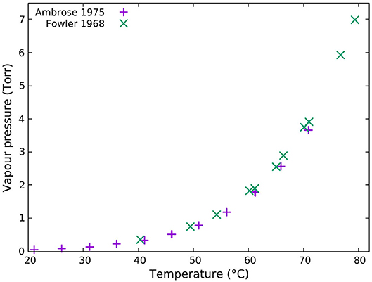
Figure 1. Naphthalene vapor pressure vs. temperature as reported by [9] (purple “+”) and [10] (green “x”).
2.2. Sublimation of Naphthalene
The process of sublimation can be examined as the result of two competing processes: evaporation and condensation [12, 13]. In a closed system in equilibrium, the rate of evaporation is equal to that of condensation which results in a constant pressure. This pressure is the vapor pressure and is a function of the sublimating material temperature. Before equilibrium is achieved, the sublimation rate will be equal to the difference between the evaporation rate and the condensation rate. The sublimation rate can be expressed mathematically by the following equation initially proposed by Miyamoto [13] and published in this form by Polzin et al. [14]:
where a is the ratio of condensing to incident molecules and is approximately equal to 1, A is the surface area of the sublimating naphthalene, M is the molecular mass, R is the universal gas constant, T is the temperature, pv is the expected vapor pressure for temperature T and p is the static pressure in the reservoir (tank) in which the sublimation takes place.
When the reservoir valve is opened, gaseous naphthalene will escape resulting in continuing sublimation occurring as p < pv. The gaseous naphthalene can be routed to the nozzle of the thruster becoming the propellant of a cold gas thruster system with the sublimation rate becoming equal to the thruster mass flow rate, .
So far, we have treated the temperature of the naphthalene during sublimation as a constant and equal to the reservoir temperature. This is not accurate as the process of sublimation is an endothermic process. The enthalpy of sublimation, also known as heat of sublimation, is the property that captures this energy requirement. For naphthalene, the enthalpy of sublimation is approximately 72.8 kJ mol−1 [15] for the proposed thruster operating temperature range (50°C to 70°C). For an expected mass flow rate ṁ = 1.6 mg s−1, this results in a sublimation power requirement Psub = 0.91 W. This power needs to be provided by the reservoir heater system, hence the total electrical power (Ptot) required for steady state operation will be:
where Ploss is the heat loss due to imperfect heat insulation of the system as well as the power required to keep the valve open, if a non-latching valve is used. Ploss in a well engineered system in vacuum can be kept to a couple of watts, which results in Ptot of a few watts, a value that is compatible with the power restrictions on a cubesat.
As described earlier, the sublimating naphthalene requires energy in the form of heat and that energy is provided by the electrically heated reservoir through radiation and conduction. The radiated heat flux j⋆ will be determined by the Stefan-Boltzmann law and is a function of the reservoir's temperature Tr and emissivity ϵr, and the propellant's effective emissivity ϵn and temperature Tn:
where σ is the Stefan-Boltzmann constant.
Conduction of heat will happen mostly through the bulk of the solid naphthalene in the reservoir and that will be determined by naphthalene's heat conductivity resulting in a heat flux of:
where k is the thermal conductivity of the propellant and ∇T the temperature gradient.
Naphthalene has a low thermal conductivity of approximately 0.1329 Wm−1 K−1 [16] (room temperature) and this results in a conducted heat flux that is of the same order of magnitude to the radiated heat flux.
The impedance in the prompt conduction of heat from the hot reservoir walls to the sublimating naphthalene can result in a localized temperature drop in the sublimating area, which in return results in a lower pv, causing a lower mass flow rate and consequentially a lower thrust. The designer of the cold gas naphthalene thruster needs therefore to ensure the heat transfer is maximized via both radiation and conduction modes from the reservoir to the propellant.
2.3. Design Details
A diagram of the proof of concept naphthalene cold gas thruster can be seen in Figure 2. The propellant is stored in a reservoir made of aluminum. It has a cylindrical shape of approximately 75 mm diameter and 50 mm length. The maximum volume of propellant it can hold is approximately 95 cm3. The reservoir lid, also made of aluminum, is held in place by four screws and has a gaseous naphthalene extraction line of internal diameter of 3 mm which is attached to a valve. Pressure sealing is achieved by a Viton® o-ring sitting in a groove on the reservoir and compressed by the lid. When fully compressed, the lid provides good thermal transfer contact with the heated reservoir, to ensure both are at the same temperature. Aluminum was selected for its excellent thermal conductivity of 237 Wm−1 K−1 as well as its compatibility with naphthalene, as mentioned earlier. The valve is a spring-loaded on/off valve which is normally closed. The body of the valve is also made of aluminum and its dimensions are 30 × 20 × 55 mm, including the solenoid. The valve used in this experiment is commercially available and supports a much higher pressure differential than the 1 atm or less, needed by the thruster. It is therefore envisaged that the final design will have a custom valve based on the same principle, smaller in size and more tightly integrated to the tank, resulting in a thruster occupying 1/3 to 1/2 of a cubesat unit, and having a wet mass (mass of propulsion system plus propellant) of no more than 0.5 kg, inclusive of the associated electronics. A 12 V solenoid is used to actuate (open) the valve. At the outlet of the valve is attached a de Laval nozzle. The nozzle is made of copper and is not optimized for the operating conditions of the system. It is envisaged the nozzle will be optimized for the selected parameters of operation in future studies. A photo of the thruster mounted on the thrust balance can be seen in Figure 3.
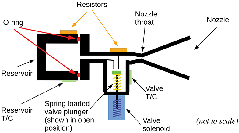
Figure 2. Diagram of the naphthalene thruster with its main components highlighted. The reservoir temperature Tr is measured by the reservoir T/C and controlled by the reservoir heater resistor; the valve temperature Tv is measured by the valve T/C and controlled by the valve heater resistor.
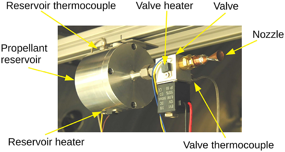
Figure 3. Photo of the naphthalene thruster proof of concept (Figure 2), mounted on the thrust balance within the Wombat space simulation chamber (Figure 4) with its main components highlighted.
There are two heating zones which are the reservoir and the valve, as seen in Figure 2. Each heating zone has its own heating element (TO-220, 100 Ω resistor), a K-type thermocouple (T/C) and an external thermostat. Each thermostat can be set individually to a hold the corresponding zone to a constant temperature. It was found that the temperature could be kept within 1°C of the set value using this system. During measurements, the valve temperature was maintained at a temperature slightly higher (here chosen to be at least 5°C) than that of the reservoir to prevent naphthalene condensation in the valve. The gas transfer line between the valve and the reservoir does not have its own heater. It instead relies on heat transfer from the valve and reservoir via conduction. Similarly, the nozzle is heated up through conduction of heat from the valve. In an initial 5.5 h long term thrust measurement experiment, a slow decrease in thrust was observed before the thruster run out of propellant. It was attributed to a decrease in the flow rate, due to a suspected cold spot in the reservoir-valve transfer line causing slow condensation of naphthalene and restricting the flow of gas. To address this problem, a simple passive insulation system consisting of a few layers of MLI (multi layer insulation) wrapped around suspected cold spots was installed and the experiment was repeated. The outcome of this intervention was an improvement in the stability of the flow rate over time, indicating that the condensation hypothesis was likely to the cause of this decrease. The thrust measurement results of both experiments are presented in section 3.2. By using this heating and insulation technique, condensation of naphthalene in that zone was limited and no blockage was ever observed in tens of hours of operation of the thruster in the lab. The thruster was mounted to the thrust balance frame via a MACOR® machinable glass ceramic adaptor, to reduce the heat loss via conduction to the balance frame. MACOR® has very low thermal conductivity of 1.46 Wm−1 K−1. No effort was made to heat insulate the thruster reservoir and valve to minimize heat loss through radiation. Despite this, the average power required to maintain the thruster at 70°C was around 4 W, increasing slightly when the valve was open. This loss can be substantially reduced in the future by using heat insulation materials and techniques commonly utilized in spacecraft for heat isolation.
As discussed in section 2.2, the designer of the cold gas naphthalene thruster needs to optimize for maximum heat transfer from the hot reservoir walls to the propellant. Such optimization was not done for this proof of concept but would be important in the design of a flight prototype.
2.4. Safety
Naphthalene is a household chemical (mothballs), commonly used to protect stored items from damage from moths. It is a flammable substance and needs to be stored and handled away from sources of ignition. When the thruster is installed in the vacuum chamber, there is no risk of fire. Naphthalene is also toxic to humans and nature, in particular aquatic life. To avoid any exposure, the loading of the tank needs to take place in a well-ventilated lab, using appropriate personal protection equipment (gloves). Once in the vacuum chamber, the vapor produced during the operation of the thruster are pumped outside, resulting in no residual smell in the lab. Appropriate signage was installed in the lab to remind the users not to dispose of any naphthalene by tipping it in the lab sink.
3. Experimental Results
3.1. Thrust Balance Set Up
The thrust measurements were conducted in the previously described Wombat space simulation chamber [17, 18] using a high sensitivity thrust balance [19], shown in Figure 4. This balance consists of a four arm pendulum suspended frame. The thruster is mounted on the frame and the operation of the thruster results in a displacement from the rest position (Figure 4). The displacement, which is proportional to the thrust force, is accurately measured by a laser triangulation displacement sensor (ILD7100), with a resolution of 0.1 μm. The balance includes a built-in calibration system consisting of a set of accurately measured weights which are placed on the balance via a pulley and controlled by a stepper motor. The calibration system is used in each measurement to confirm the conversion constant from displacement to force. When a force is applied to the frame by the thruster, the pendulum starts oscillating. This oscillation is dampened by a previously described magnetic damper [19]. The time constant of the dampening system is in the order of a few seconds. The thruster is attached on the frame using a MACOR® adaptor to ensure minimal thermal leakage from the warm reservoir to the room temperature frame (Figure 4). A set of vacuum feedthrough connections on the vacuum chamber was used to enable connection of heater power, valve control, and temperature measurements to the power supply, valve control signal source and thermostats, all located outside the chamber.
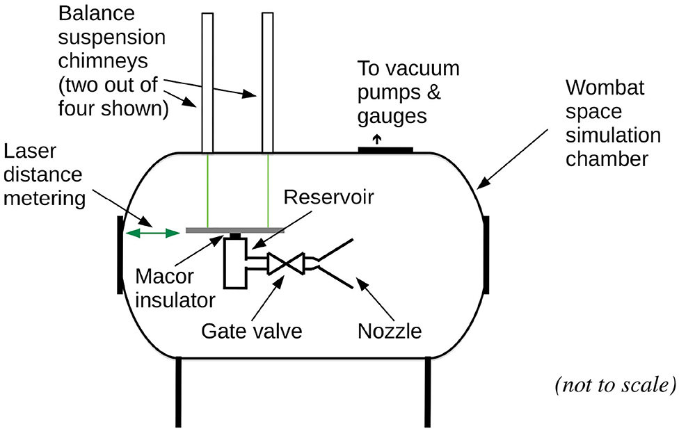
Figure 4. Diagram of the naphthalene cold gas thruster mounted in the Wombat space simulation chamber thrust balance [17–19]. Not seen in the diagram are the feed through connections to valve control, heating elements, and thermocouples.
3.2. Thrust Measurements
An initial thrust measurement experiment was performed to quantify the performance and stability of the thruster. Both short term (within a single burn) and long term (from the beginning of thruster operation to the exhaustion of propellant) variations are of interest to the thruster designer and cubesat operator. A small amount of naphthalene (10 g) was placed in the reservoir and the thruster was configured to run continuously until the propellant is fully exhausted. The thruster was set up for 12 s burns and 60 s period resulting in a duty cycle D = 0.2. This combination of burn time and period was selected as it provided an opportunity for the thruster reservoir to fully recover (p = pv) between burns, and is a variable that can be altered by the thruster designer to suit the specific propulsion and operating requirements of the mission. The reservoir was set to and the valve was set to , both held to ± 1°C by their respective thermostats. Tv needs to be higher than Tr in order to prevent condensation of naphthalene in the valve body, as this could affect the flow rate or in the worst case, completely block the movement of gas. The value of Tv is not critical as long as it is higher than Tr under all operating conditions. The vacuum chamber pressure measured using an ion gauge with the thruster valve shut was ~ 5 × 10⁻⁵ Torr, increasing to ~ 5 × 10⁻⁴ Torr upon opening the valve. The measured chamber pressure is at least three orders of magnitude lower compared to the expected pressure in the reservoir due to the naphthalene vapor pressure at the operating temperature range of 50°C to 70°C (Figure 1). This ensures the thruster is operating in choked flow conditions, as described in detail by [11].
The experiment took a bit over 5.5 h of elapsed time, tel, (defined as the absolute time from the beginning of the experiment) to complete. During that time, over 330, 12 s burns were performed. Thrust measurements from two individual burns taken near the beginning (tel ≈ 1 h) and the end (tel ≈ 5.4 h) of the run are shown in Figure 5. An 'ideal' burn with constant thrust (of arbitrary value for visualization purpose) during its 12 s duration is also shown in this figure as a red dashed line overlapping with the two measurements. The burn early in the run (purple line) indicated a thrust of ~ 0.67 mN (average thrust over the 12 s burn time) and appears to be deviating very little from the ideal burn. The slow rise and fall times as well as the damped oscillation following the opening and closing of the valve, are a result of the thrust balance damping mechanism and do not relate to the actual thruster performance. A small decline in the thrust can be seen as the valve is about to close and that can be attributed to the lack of pressure regulation. The exact magnitude of that decline is a function of the design parameters such as reservoir volume and propellant mass. Lower mass of propellant in the reservoir results in lower sublimating area A and therefore a lower gas production rate, as implied by equation 1. Larger reservoir volume results in more gaseous naphthalene available to the thruster. As an extension to this, we can deduce that the shape of the reservoir and the mechanism employed to keep the solid naphthalene secure in zero gravity conditions are also going to have an impact in this decrease.
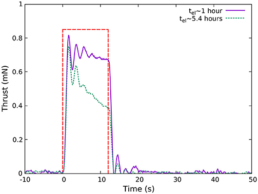
Figure 5. Plot of thrust vs. time of two 12 s burns taken at 1 h (purple solid line) and 5.4 h (green dotted line) elapsed time (tel). The red dashed line serves as a visual guide representing an “ideal” 12 s burn. At the beginning of the run (tel = 0), the reservoir had 10 g of naphthalene in it. The duration of the run was approximately 5.5 h and throughout the run, the temperature of the reservoir was maintained at 70°C. The damped oscillation seen at the beginning and end of each burn is due the effect of the magnetic damper in the thrust balance and is discussed in section 3.1.
The effect of this process on the thrust generation is more pronounced on the burn closer to the end of the run, shown in Figure 5 as a green line. In this case, the opening of the valve results in a relatively large thrust as the reservoir pressure had enough time to recover since the previous burn, but the sublimating area A is now much less compared to the beginning of the run and the sublimation rate is not high enough to sustain a high mass flow rate of the expelled propellant resulting in a rapid decline.
To quantify the effect of this thrust decline over time, two runs of 10 g of naphthalene to exhaustion were carried out, with the resulting average burn thrust plotted vs. elapsed time shown in Figure 6. The purple line data was obtained with no insulation in the reservoir-valve transfer line and nozzle. A slow but steady decline can be seen in during the first ~ 5 h of operation, followed by a rapid decline as the propellant is about to run out. This decline is mainly due to the reduction of the sublimating area over time discussed earlier, however it was suspected that naphthalene may be depositing in a cold spot somewhere in the reservoir transfer line or valve-nozzle line, resulting in a reduction in the flow rate. The second 10 g run measurement (green line in Figure 6) was conducted, this time having a few layers of multi layer insulation (MLI) covering both the transfer line and nozzle. This resulted in a decrease in the slow decline over time, maintaining a more consistent flow rate and was eventually followed by the rapid decline indicating the exhaustion of the propellant.
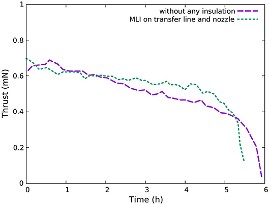
Figure 6. Measured thrust vs. time. Thruster was configured for 12 s burns every minute, at 70°C reservoir temperature. The reservoir was loaded with 10 g of naphthalene at the beginning of the run and was operated continuously until the propellant was fully exhausted. The purple dashed line was obtained with no insulation on the transfer line and nozzle and the green dotted line was obtained after insulating the transfer line and nozzle with multi-layer insulation (MLI), as discussed in section 3.2.
The relation between the vapor pressure and temperature shown in Figure 1, offers a simple solution to mass flow rate control in the absence of a mass flow regulator. To get more insight, a second set of thrust measurements was performed to estimate the thrust and mass flow rate as a function of the reservoir temperature Tr with the results shown on Table 1. In these experiments, the reservoir was loaded with 10 g of propellant and the thruster was then run at a fixed 20% duty cycle D (60 s period) for an elapsed time tel of ≈ two to three hours in order to obtain reliable statistics. This was repeated for reservoir temperatures of 70, 65, 60, 55, and 50°C. A representative sample of burns covering the duration of each run was examined and an average thrust (FT) was obtained for each reservoir temperature. The average thrust was 0.6 mN at 70°C dropping as the reservoir temperature is decreased to 0.11 mN at 50°C. For each measurement, the mass difference Δm was obtained by weighing the thruster reservoir before and after the run, using a lab scale with a precision of 0.1 g. The average mass flow rate ṁ for that operating period was then calculated according to the equation:
The specific impulse Isp was then calculated by using the following equation:
where g0 is the standard gravity (9.81 m s−2). The measured thrust and calculated mass flow rate and specific impulse are summarized in Table 1. They represent the typical performance to be expected during the useful life of the thruster, prior to the rapid deterioration that takes place as the propellant is about to run out. The calculated specific impulse Isp at 60°C to 70°C appears to be constant at about 24.6 s, allowing some flexibility to the thruster designer to select a lower mass flow rate without compromising the propellant use efficiency of the system.
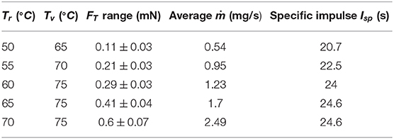
Table 1. Measured thrust FT, and calculated mass flow rate ṁ and specific impulse Isp of the naphthalene cold gas thruster for various reservoir and valve temperatures Tr and Tv, respectively.
4. Conclusions
The presented study has investigated the use of naphthalene as a propellant for a cold gas cubesat thruster proof of concept. The thruster concept is based on the sublimation of solid naphthalene which produces a reliable flow rate of gaseous naphthalene, used through a nozzle to produce thrust. Being stored in solid state, naphthalene does not have the disadvantages associated with the sloshing of liquid propellants or extremely high pressure associated with gas propellants. The proposed design utilizes a two-zone heating system. There was no malfunction due to naphthalene solidifying in any part of the gate valve or distribution system during the many tens of hours of operation of this system in the space simulation chamber. This supports the hypothesis that naphthalene is a propellant with limited engineering challenges to the thruster designer. It was shown that the naphthalene cold gas thruster can produce thrust around 0.6 mN at a specific impulse of 24.6 s and at a propellant temperature of 70°C. This is achieved within the power limitations of a cubesat. The thrust measurements presented in this paper indicate that a total impulse of at least 24 Ns per 100 g (86.2 cm3) of propellant can be achieved by a carefully designed, compact naphthalene cold gas thruster. To put this in perspective, 24 Ns of total impulse could be used by a typical 2.66 kg 2U cubesat in a low earth orbit (LEO) at 400 km to raise its orbit via a Hohmann transfer to approximately 416 km. This maneuver can increase its life in space by approximately a year, depending on solar conditions and the drag coefficient of the cubesat. It can be also used to efficiently assist deorbiting it. Despite the lack of a pressure regulation valve to control the mass flow rate, the variability in the thrust produced was found to be low and would make this type of thruster a suitable system for station keeping of LEO satellites. Future work will aim to improve the performance by using an optimized nozzle for the operating conditions of this thruster, and improve the thermal control to confirm suitability and reliability of the system for testing in space.
Data Availability Statement
The raw data supporting the conclusions of this article will be made available by the authors, without undue reservation.
Author Contributions
This work presented in this paper is DT's Ph.D. student work and has been supervised by CC and RB. All authors contributed to the article and approved the submitted version.
Conflict of Interest
The authors declare that the research was conducted in the absence of any commercial or financial relationships that could be construed as a potential conflict of interest.
References
2. Kulu E. Nanosat Database (2019). Available online at: https://www.nanosats.eu
3. Curtis HD. Orbital Mechanics for Engineering Students. Oxford: Butterworth-Heinemann Publications (2013).
4. Sidi MJ. Spacecraft Dynamics and Control. Cambridge University Press (1997). Available online at: https://www.cambridge.org/core/product/identifier/9780511815652/type/book
5. NASA. State of the Art of Small Spacecraft Technology. State of the Art of Small Spacecraft Technology (2018). Available online at: https://sst-soa.arc.nasa.gov/
6. Lemmer K. Propulsion for CubeSats. Acta Astron. (2017) 134:231–43. doi: 10.1016/j.actaastro.2017.01.048
7. Scharlemann C, Tajmar M, Buldrini N, Krejci D, Seifert B. Propulsion for nanosatellites. In: 32nd International Electric Propulsion Conference. Wiesbaden (2011).
8. Vargel C. Corrosion of Aluminium. Oxford: Elsevier Ltd (2004). doi: 10.1016/B978-0-08-044495-6.X5000-9
9. Ambrose D, Lawrenson IJ, Sprake CHS. The vapour pressure of naphthalene. J Chem Thermodyn. (1975) 7:1173–6. doi: 10.1016/0021-9614(75)90038-5
10. Fowler L, Trump WN, Vogler CE. Vapor pressure of naphthalene: new measurements between 40°C and 180°C. J Chem Eng Data. (1968) 13: 209–10. doi: 10.1021/je60037a020
11. Ho TS, Charles C, Boswell RW. A comprehensive cold gas performance study of the pocket rocket radiofrequency electrothermal microthruster. Front Phys. (2017) 4:55. doi: 10.3389/fphy.2016.00055
12. Langmuir I. The constitution and fundamental properties of solids and liquids. Part I. Solids. J Am Chem Soc. (1916) 38:2221–95. doi: 10.1021/ja02268a002
14. Polzin KA, Seixal JF, Mauro SL, Burt AO, Martinez A, Martin AK. The iodine satellite (iSat) propellant feed system - design and development. In: 35th International Electric Propulsion Conference (IEPC) Atlanta, GA (2017). Available online at: https://ntrs.nasa.gov/archive/nasa/casi.ntrs.nasa.gov/20170012401.pdf
15. Chickos JS, Acree WE. Enthalpies of sublimation of organic and organometallic compounds. 1910-2001. J Phys Chem Refer Data. (2002) 31:537. doi: 10.1063/1.1475333
16. Orain M, Baranger P, Rossow B, Grisch F. Fluorescence spectroscopy of naphthalene at high temperatures and pressures: implications for fuel-concentration measurements. Appl Phys B. (2011) 102:163–72. doi: 10.1007/s00340-010-4353-7
17. Charles C, Boswell RW, Bish A. Variable frequency matching to a radiofrequency source immersed in vacuum. J Phys D. (2013) 46:365203. doi: 10.1088/0022-3727/46/36/365203
18. Charles C, Boswell RW, Bish A, Khayms V, Scholz EF. Direct measurement of axial momentum imparted by an electrothermal radiofrequency plasma micro-thruster. Front Phys. (2016) 4:19. doi: 10.3389/fphy.2016.00019
Keywords: napthalene, cold gas thruster, thruster, cubesat thruster, thruster propellant
Citation: Tsifakis D, Charles C and Boswell R (2020) Naphthalene as a Cubesat Cold Gas Thruster Propellant. Front. Phys. 8:389. doi: 10.3389/fphy.2020.00389
Received: 24 June 2020; Accepted: 11 August 2020;
Published: 23 September 2020.
Edited by:
Ferenc Kun, University of Debrecen, HungaryReviewed by:
Reinaldo Roberto Rosa, National Institute of Space Research (INPE), BrazilMengu Cho, Kyushu Institute of Technology, Japan
Copyright © 2020 Tsifakis, Charles and Boswell. This is an open-access article distributed under the terms of the Creative Commons Attribution License (CC BY). The use, distribution or reproduction in other forums is permitted, provided the original author(s) and the copyright owner(s) are credited and that the original publication in this journal is cited, in accordance with accepted academic practice. No use, distribution or reproduction is permitted which does not comply with these terms.
*Correspondence: Dimitrios Tsifakis, ZGltaXRyaW9zLnRzaWZha2lzQGFudS5lZHUuYXU=