 Xi Gao
 Yan Zhang2
- 1School of Electrical and Information Engineering, Guangxi University of Science and Technology, Liuzhou, China
- 2School of Information and Communication, Guilin University of Electronic Technology, Guilin, China
We propose a high refractive index metamaterial (HRIM)that is composed of two identical patch arrays symmetrically etched on both sides of a dielectric plate. By reducing the gap of adjacent patches and the thickness of dielectric plate, the proposed metamaterial can suppress the diamagnetic response and enhance the capacitance coupling, so that the refractive index of the metamaterial is higher than 10 in wideband from 4 to 8 GHz. Attributing to the property of high refractive index, the metamaterial can effectively improve the performance of a microstrip antenna when it is loaded as a superstrate. The measured results reveal that the antenna has an impedance bandwidth (S11 < −10 dB) of 690 MHz (12.4%) and a maximum gain of 13 dB appearing at 5.6 GHz. The 1 dB and 3 dB gain bandwidths are 380 MHz (6.7%) and 590 MHz (10.3%), respectively. Fortunately, the profile of the antenna is only 0.19λ0 (λ0is the free space wavelength at central frequency). Furthermore, the profile can be further reduced to 0.15λ0 when the radiation patch of the antenna is surrounded by another metamaterial.
Introduction
Microstrip patch antennas (MPAs) are a widespread choice in many existing and future wireless communication systems due to the advantages of low profile, light weight, low cost, and ease of fabrication. However, the conventional MPAs have major disadvantages of narrow impedance bandwidth and low gain, which limit their practical applications.
Metamaterials are artificial structures formed by periodically or aperiodically arranging their unit cells, which can freely manipulate the electromagnetic (EM) waves. Attributing to the exotic properties, metamaterials can be used as a superstrate or substrate in antennas to improve antenna performance, such as increasing gain and impedance bandwidth [1–8]. A typical application of metamaterial is loaded as a superstrate on planar antennas to form Fabry-Perot-Cavity-like (FPC-like) leaky wave antenna [9–12]. Furthermore, the ray optics theory has been successfully employed to study the working mechanism of FPC-like antennas. In [11], for instance, an FPC-like antenna formed by loading a multi-layer metamaterial superstrate is successfully obtained high performance. The directivity of the antenna is 16.9 dB and the 3 dB bandwidth reaches 10.7%. Subsequently, a quad-layer partially reflective surface (PRS) is employed as a superstrate to improve antenna performance, in which the peak gain is 15.5 dB and the 1 dB gain bandwidth is 10% [12]. These proposed antennas possess many advantages, such as high gain, high efficiency and simply feeding network, but they also have an obvious disadvantage of increasing profile (the total profile is over λ/2). In order to reduce the profile, an artificial magnetic conductor (AMC) is proposed as ground plane or superstrate of antenna [13, 14]. At specific frequency, the AMC can reflect electromagnetic waves with zero phase shift. Based on this property, Ourir et al. designed an ultrathin and high directive antenna by employing the combination of an AMC and a PRS superstrate [15]. In this design, the antenna profile is drastically reduced to λ/60. However, the above antenna shows a limitation of narrow bandwidth. Therefore, it remains a challenging task to achieve a high-performance antenna with sub-wavelength profile.
In this paper, we proposed a novel antenna that is formed by loading three layer HRIMs as a superstrate of MPA. Each layer of the metamaterial is two identical patch arrays spaced by a dielectric plate. By decreasing the gap between adjacent patches and the thickness of dielectric plate, the metamaterial has a high refractive index of 10 in wideband from 4 to 8 GHz. Thanks to the high refractive index of superstrate, the profile of the proposed antenna is significantly reduced to 0.19λ0. The experimental results show that the antenna achieves a relative impedance bandwidth of 12.4% (from 5.21 to 5.9 GHz) for S11 < −10 dB, and has a 3 dB gain bandwidth of 590 MHz (10.3%). Compared with the conventional MPAs, the proposed antenna gain is increased by at least 3 dB. In order to further reduce the profile of antenna, the radiation patch of MPA is surrounded by another patch array (this antenna is called as type II antenna). Unlike metal ground, the patche array can adjust the phase of reflective wave by changing its geometric parameters. When we choose adaptive dimension of patch array, the profile of type II antenna can further reduce to 8 mm (0.15λ0). Moreover, the experimental results reveal that the impedance bandwidth is extended to 860 MHz, with the relative bandwidth of 15.7%, and the maximum gain reaches 13.05 dB at 5.7 GHz.
Design of MPA Based on High Refractive Index Metamaterial
Design of Metamaterial
Figure 1A presents the unit cell of the proposed metamaterial, which is a bi-layer patch array spaced by a dielectric substrate. The dielectric substrate is Rogers RO4350B with relative permittivity εr = 3.48, loss angle tandenta value tan δ = 0.0037, and thickness t2 = 0.508 mm. The metal patches on both sides of dielectric plate have the same side length of b = 5.9 mm. The periods of the unit cell along x- and y-directions are set as a = 6 mm. To investigate the EM response of the metamaterial, we first extract the effective permeability and permittivity from S parameters, by using the commercial software CST Microwave Studio. In simulation, the periodic structure is simplified as a unit cell with periodic boundary conditions along the x- and y-directions. Meanwhile, an x-polarized normal incident wave is used to excite the unit cell. According to the method proposed in [16], the extracted effective permeability and permittivity are presented in Figure 1B.
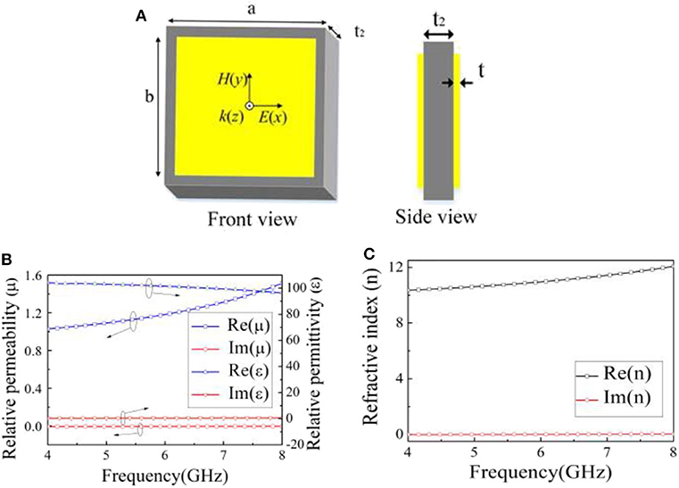
Figure 1. (A) The front and side views of the HRIM. (B) The effective permittivity and permeability of HRIM. (C) The refractive index of HRIM.
To verify the validity of the retrieved effective permeability and permittivity, we also simulate the S parameters of a homogenous dielectric plate whose permeability and permittivity are equal to the retrieved parameters of the metamaterials (the results are not shown). Consequently, we find that the S parameters of the homogenous dielectric plate have good consistency with those of metamaterial, demonstrating the accuracy of the retrieved permeability and permittivity. Based on these retrieved parameters, we further obtain the refractive index of the proposed metamaterial [17], which is presented in Figure 1C. It is observed that in the frequency range of 4 to 8 GHz, the refractive index is higher than 10, demonstrating the property of high refractive index.
To understand the physical mechanism for forming high refractive index, we investigate the refractive index varying with parameters b and t2 for fixed parameter a, as shown in Figure 2. Figure 2A illustrates the refractive index as a function of b when the thickness of dielectric plate is t2 = 0.508 mm. We clearly see that the refractive index increases with the increasing of parameter b. Figure 3 presents the electric field distributions on the surface of metamaterial, which indicates that the electric fields are mainly concentrated at the gap of adjacent patches, implying strong capacitive coupling. As we known, the capacitive coupling can be enhanced when the parameter b is increased. The enhanced capacitive coupling will further improve the refractive index of the metamaterial. Figure 2B reveals the refractive index varying with the dielectric thickness t2 for fixed parameter b (5.9 mm). It is noted that the refractive index is increased with decreasing of t2. As presented in Figure 4, the induced currents on the top layer are antiparallel to those on the bottom layer, which forms a current loop with the displacement current in the dielectric plate. Furthermore, the induced circulation produces magnetic moments in the same direction as the external magnetic field, which forms a bigger effective permeability, resulting in a high refractive index. Based on these investigations, we can adjust the side length of metal patch and the thickness of dielectric plate to control the effective permittivity and permeability, thereby controlling its effective refractive index.
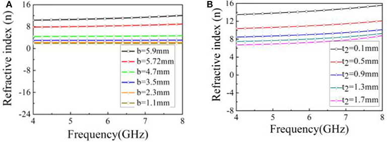
Figure 2. (A) Influence of the size of metal patch on the refractive index of HRIM. (B) Effect of the dielectric thickness t2 on the refractive index of HRIM.
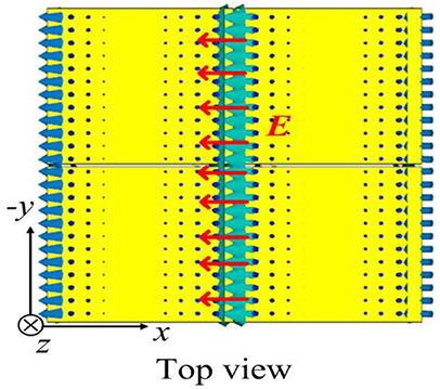
Figure 3. The electric field distribution on the surface of HRIM.
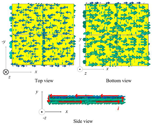
Figure 4. The surface current distributions on the surface of HRIM.
MPA Loaded With HRIM
Here, we take a conventional MPA as an example to study the influence of the proposed HRIM on antenna performance. Figure 5A illustrates the designed antenna that is formed by loading three layer HRIMs over a MPA, which is also called as type I antenna. The MPA is etched on a substrate (F4B) with a dielectric constant of 2.65, loss tangent of 0.001, and thickness of t1 = 1.5 mm, as shown the enlarged area in Figure 5A. The three layer HRIMs have the same overall size of 60 × 60 mm but different refractive index. The middle layer, namely core layer, has refractive index higher than 10. However, the upper and bottom layers, which are called matching layer, have the same refractive index of 7.5 (see the red line in Figure 2A). The matching layers are symmetrically located on both sides of core layer to decrease the reflection at the interface of air and core layer. For convenience of research, we look the three layer HRIMs as a whole, as shown in Figure 5B. In this case, a resonant cavity between HRIM superstrate and MPA is formed. Therefore, multiple reflections will occur in this resonant cavity. When the resonant condition of the resonant cavity is met with, the antenna performance can be greatly improved. Here, the resonant frequency of this cavity is designed at 5.5 GHz, whose resonant condition is determined by the following equation [18]:
where φ1 and φ2 are the reflection phases at superstrate and MPA, respectively, λ0 corresponds to the free space wavelength at 5.5 GHz, N is the resonance mode number. The parameter h1 denotes the distance between superstrate and MPA. It is noted that h1 is a critical parameter that determines the profile of antenna. From Equation (1), we see that the parameter h1 is determined by the difference between φ1+ φ2 and resonance mode number N. Usually, the zeroth mode (N = 0) is considered, so that the φ1+ φ2 is the only parameter to impact the value of h1. On the other hand, φ2 is constant to 180° because it denotes the phase of EM wave reflected by the metal ground of MPA. Therefore, the value of h1 is actually decided by the reflection phase (φ) at the superstrate. For x-polarized incidence, the reflection phase (φ1) is presented in Figure 6. It can be seen that the reflection phase φ1 at 5.5 GHz is−121.9°. This value corresponds to a cavity thickness h1 = 4.5 mm (0.08λ0). Actually, the superstrate can be looked as a cascaded circuit comprised of the matching layer, the core layer, and the air gap between them. Based on the theory in [19], the thickness of the matching layers including their air gap should be approximately equal to λ/4 (λ is guide wavelength of superstrate) to realize the minimum reflection between core layer and free space, namely
where nc is the refractive index of core layer, m is distance between core layer and matching layer, and t2 is the thickness of dielectric plate. According to equation (2), we find that the whole thickness of superstrate can be reduced effectively when we increase the nc of core layer. For nc = 10, the overall height of the type I antenna is reduced to 10.5 mm (0.19 λ0).
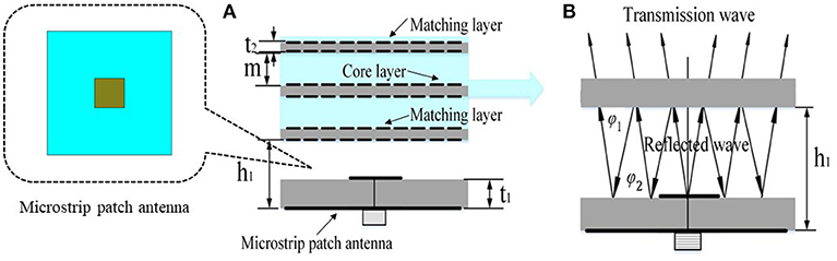
Figure 5. (A) The side view of the proposed type I antenna. (B) The model of the antenna when the superstrate of three-layer metamaterial is looked as a whole.
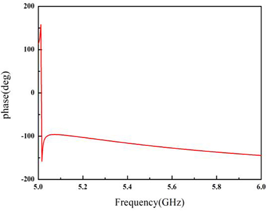
Figure 6. Reflection phase at superstrate for x-polarized incident waves.
To further reduce the profile of the proposed antenna, the radiation patch is surrounded by another patch array with patch length l and period p, as shown in Figure 7A. For convenience, this antenna is called as type II antenna. In type II antenna, it has the same superstrate as that in type I antenna. For the patch array, the reflection phase is controlled by its geometric parameters l and p. Figure 7B illustrates the reflection phase varying with frequency when l = 5.72 mm and p = 6 mm. We see that the φ2 at 5.4 GHz (the center frequency of type II antenna) is not 180° but 127.9°. By substituting this phase into formula (1), we calculate the height of the cavity, which is h1-t1 = 0.5 mm. Finally, the whole height of the type II antenna is reduced to 8 mm (0.15 λ0).
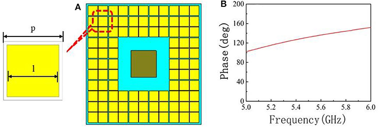
Figure 7. (A) The radiation patch surrounded with patch array. (B) The phase of reflection wave for x-polarized incident wave.
Experimental Results
To experimentally verify the performance of the proposed antennas, we fabricate the HRIMs and MPA, and assemble them together, as shown in Figure 8. The S11 parameters are measured by using the Agilent 8753ES vector network analyzer. Figure 9A presents the experimental and simulated S11 parameters of type I antenna, which shows a good consistency. The experimental results reveal that in the frequency of 5.21 to 5.9 GHz (690 MHz), the parameter S11 is less than−10 dB, with relative bandwidth of 12.4%. For comparison, we also show the simulated results of type I antenna with different refractive index of core layer, such as nc = 4 and 7, and the antenna without metamaterial superstrate. As presented in Figure 9A, we see that the refractive index of core layer has greatly influence on the impedance bandwidth of S11. Our proposed antenna (type I antenna) occupies the widest impedance bandwidth. Figure 9B presents the measured and simulated gains. The experimental results are good agreement with simulations. In the operation band from 5.21 to 5.9 GHz, the gain is higher than 8 dB, and the max gain reaches 13 dB. From simulated results shown in Figure 9B, we further observe that the refractive index of core layer has great influence on antenna gain. The maximum gain of type I antenna is much higher than the antenna loaded with lower refractive index metamaterial and the antenna without metamaterial superstrate. Additionally, the 3 dB gain bandwidth of type I antenna is 590 MHz (10.3%). Figures 10A,B present the comparison of measured and simulated radiation patterns for type I antenna at 5.62 GHz, which shows good consistency. We also find that the 3 dB beam width in both E- and H-planes are about 30°.
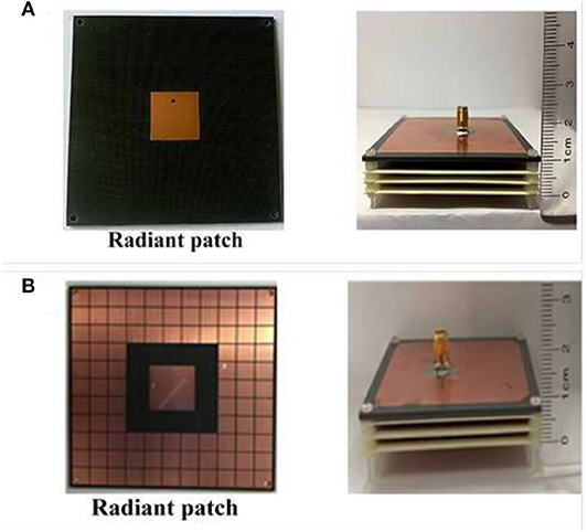
Figure 8. Photograph of the fabricated antenna. (A) Type I antenna. (B) Type II antenna.
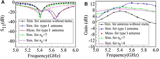
Figure 9. (A) Return loss and (B) gain for type I antenna with different refractive index of core layer and the antenna without metamaterial.
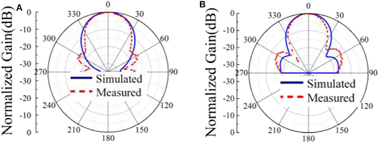
Figure 10. Radiation patterns of the type I antenna at 5.62GHz. (A) E-plane and (B) H-plane.
Figure 11A illustrates the simulated and measured results of type II antenna. It is observed that the simulated reflection coefficient S11 < −10 dB ranges from 5.03 GHz to 5.81 GHz, with a relative bandwidth of 14.4%, and the measured reflection coefficient S11 < −10 dB ranges from 5.05 GHz to 5.9 GHz, with a relative bandwidth of 15.5%. The discrepancy between experimental results and simulations may be caused by the tolerances in process of assembling superstrate and fabrication. Figure 11B presents a comparison of gain between measured results and simulations, from which we see that they show good consistency and the max gain reaches 13 dB at 5.7 GHz. The E- and H-plane radiation patterns at 5.7 GHz are presented in Figure 12. Moreover, by comparing the simulation and experimental results between type I and type II antennas (Figures 9–12), we conclude that the type II antenna has better performance than the type I antenna, while its profile is further reduced to 0.15 λ0.
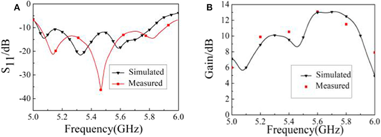
Figure 11. The simulated and measured S11 parameters and gains for type II antenna. (A) S11 parameters, (B) gain.
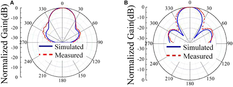
Figure 12. (A) E-plane and (B) H-plane radiation patterns of the type II antenna at 5.7 GHz.
Conclusion
We presented a high gain and low profile MPA loaded with three layer HRIMs. The performance of the antenna (type I antenna) is significantly improved due to the high refractive index of the HRIM superstrate. To verify the excellent performance, we fabricated a sample and measured its S11 parameter and gain. The experimental results show that the impedance bandwidth of S11 < −10dB is 690 MHz, and the measured antenna gain is higher than 8 dB in operation frequency band. At the same time, the proposed antenna has low profile of 0.19λ0. To further reduce the profile of antenna, a type II antenna was designed, in which the radiation patch of MPA is surrounded by another patch array that is employed to adjust the phase of reflection wave. Simulation and experimental results demonstrate that the type II antenna has a better radiation performance than the type I antenna while its profile is reduced to 0.15λ0.
Data Availability Statement
All datasets presented in this study are included in the article/supplementary material.
Author Contributions
XG and YZ proposed and design the theory of high refractive index metamaterial and high performance antenna. SL supervised the design and experiments. All authors contributed to the article and approved the submitted version.
Funding
This work was supported in part by the National Natural Science Foundation of China under Grants 61761010, and in part by the Natural Science Foundation of Guangxi Province under Grants 2018GXNSFAA281193, 2017GXNSFAA198048.
Conflict of Interest
The authors declare that the research was conducted in the absence of any commercial or financial relationships that could be construed as a potential conflict of interest.
References
1. Cai T, Wang G, Zhang X, Wang Y, Zong B, Xu H. Compact microstrip antenna with enhanced bandwidth by loading magneto-electro-dielectric planar waveguided metamaterials. IEEE Trans Antennas Propag. (2015) 63:2306–11. doi: 10.1109/TAP.2015.2405081
2. Ren J, Gong S, Jiang W. Low-RCS monopolar patch antenna based on dual-ring metamaterial absorber. IEEE Antennas Wireless Propag Lett. (2018) 17:102–5. doi: 10.1109/LAWP.2017.2776978
3. Sun M, Chen Z, Qing X. Gain enhancement of 60-ghz antipodal tapered slot antenna using zero-index metamaterial. IEEE Trans Antennas Propag. (2013) 61:1741–64. doi: 10.1109/TAP.2012.2237154
4. Wu W, Guan B, Xiang T. A bandwidth enhancement for metamaterial microstrip antenna. Microwave Opt Technol Lett. (2017) 59:3076–82. doi: 10.1002/mop.30872
5. Lin W, Chen S-L, Ziolkowski RW, Guo YJ. Reconfigurable, wideband, low-profile, circularly polarized antenna and array enabled by an artificial magnetic conductor ground. IEEE Trans. Antennas Propag. (2018) 66:1564–9. doi: 10.1109/TAP.2018.2790437
6. Lin D, Szabo Z, Qing X, Li E-P, Chen ZN. A high gain antenna with an optimized metamaterial inspired superstrate. IEEE Trans Antennas Propag. (2012) 60 60:6018–23. doi: 10.1109/TAP.2012.2213231
7. Hou QW, Su YY, Zhao XP. A high gain patch antenna based PN zero permeability metamaterial. Microwave Opt Technol Lett. (2014) 56:1065–9. doi: 10.1002/mop.28261
8. Prakash P, Abegaonkar MP, Basu A, Koul SK. Gain enhancement of a CPW-fed monopole antenna using polarization insensitive AMC structure. IEEE Antennas Wireless Propag Lett. (2013) 12:1315–8. doi: 10.1109/LAWP.2013.2285121
9. Gardelli R, Albani M, Capolino F. Array thinning by using antennas in a Fabry-Perot cavity for gain enhancement. IEEE Trans Antennas Propag. (2006) 54:1979–90. doi: 10.1109/TAP.2006.877172
10. Lee YJ, Yeo J, Mittra R, Park WS. Design of a high directivity electromagnetic bandgap (EBG) resonator antenna using a frequency selective surface (FSS) superstrate. Microwave Opt Technol Lett. (2004) 43:462–7. doi: 10.1002/mop.20502
11. Konstantinidis K, Feresidis AP, Hall PS. Broadband sub-wavelength profile high-gain antennas based on multi-layer metasurfaces. IEEE Trans Antennas Propag. (2015) 63:423–7. doi: 10.1109/TAP.2014.2365825
12. Pei-Yuan Q, Lu-Yang J, Shu-Lin C, Yingjie JG. Dual-polarized wideband fabry-perot antenna with quad-layer partially reflective surface. IEEE Antennas Wireless Propag. (2018) 17:551–4. doi: 10.1109/LAWP.2018.2802439
13. Attia H, Yousefi L, Ramahi OM. Analytical model for calculating the radiation field of microstrip antennas with artificial magnetic superstrates: theory and experiment. IEEE Trans Antennas Propag. (2011) 59:1438–45. doi: 10.1109/TAP.2011.2122295
14. Feresidis AP, Goussetis G, Shenhong Wang, Vardaxoglou JC. Artificial magnetic conductor surfaces and their application to low-profile high-gain planar antennas. IEEE Trans Antennas Propag. (2005) 53:209–15. doi: 10.1109/TAP.2004.840528
15. Ourir, de Lustrac A, Lourtioz J-M. All-metamaterial-based sub-wavelength cavities for ultrathin directive antennas. Appl Phys Lett. (2006) 88:84103. doi: 10.1063/1.2172740
16. Chen XD, Grzegorczyk TM, Wu BI, Pacheco JJ, Kong AJ. Robust method to retrieve the constitutive effective parameters of metamaterials. Phys Rev E. (2004) 70:016608. doi: 10.1103/PhysRevE.70.016608
17. Shin J, Shen JT, Fan S. Three-dimensional metamaterials with an ultrahigh effective refractive index over a broad bandwidth. Phys Rev Lett. (2009) 102:093903. doi: 10.1103/PhysRevLett.102.093903
18. Zhang L, Wan X, Lin S, Yin JY, Zhang Q, Wu HT, et al. Realization of low scattering for a high-gain Fabry-Perot antenna using coding metasurface. IEEE Trans. Antennas Propag. (2017) 65:3374–3383. doi: 10.1109/TAP.2017.2700874
Keywords: metasurface, high refractive index, antenna, high gain, subwavelength profile
Citation: Gao X, Zhang Y and Li S (2020) High Refractive Index Metamaterial Superstrate for Microstrip Patch Antenna Performance Improvement. Front. Phys. 8:580185. doi: 10.3389/fphy.2020.580185
Received: 05 July 2020; Accepted: 20 August 2020;
Published: 18 September 2020.
Edited by:
Jinhui Shi, Harbin Engineering University, ChinaReviewed by:
Feng Lan, University of Electronic Science and Technology of China, ChinaLin Chen, University of Shanghai for Science and Technology, China
Copyright © 2020 Gao, Zhang and Li. This is an open-access article distributed under the terms of the Creative Commons Attribution License (CC BY). The use, distribution or reproduction in other forums is permitted, provided the original author(s) and the copyright owner(s) are credited and that the original publication in this journal is cited, in accordance with accepted academic practice. No use, distribution or reproduction is permitted which does not comply with these terms.
*Correspondence: Xi Gao, Z2FvX3hpNzZAMTYzLmNvbQ==; Simin Li, c2ltaW5sQGd1ZXQuZWR1LmNu