 Samira Aghayee
 Mitchell Weikert1
 Phillip Alvarez
 Gabriel A. Frank
 Wolfgang Losert
- 1Department of Physics, University of Maryland, College Park, MD, United States
- 2Department of Life Sciences and The National Institute for Biotechnology in the Negev, Ben-Gurion University of the Negev, Beer Sheva, Israel
For their capacity to shape optical wavefronts in real time into any desired illumination pattern, phase-only Spatial Light Modulators (SLM) have proven to be powerful tools for optical trapping and micromanipulation applications. SLMs are also becoming increasingly utilized in selective photo-stimulation of groups of neurons in the brain. However, conventional SLM based wavefront modulation introduces artifacts that are particularly detrimental for photo-stimulation applications. The primary issue is the unmodulated light that travels along the 0th order of diffraction. This portion of light is commonly blocked at the center of the object plane, which prevents photo-stimulation in the blocked region. We demonstrate a virtual lens configuration that moves the 1st order diffraction with the desired illumination pattern into the Fourier plane of the 0th order light. This virtual lens setup makes the whole field of view accessible for photo-stimulation and eliminates the need for removing the 0th order light in two-photon applications. Furthermore, in an example application to reconstruct a pattern consisting of an array of points, the virtual lens configuration increases the uniformity of the intensities these points. Moreover, diffraction-induced artifacts are also significantly reduced within the target plane. Therefore, our proposed high fidelity configuration yields target points with high signal to noise ratio.
Introduction
Optogenetics has brought transformational capabilities to neuroscience: the ability to not only measure but also manipulate the activity of neurons by light targeted at single neurons. This has fundamentally altered how we can address two challenges that are the essence of neuroscience: understanding neuronal connectivity patterns and spatiotemporal patterns of activity in the brain.
Optically measuring the activity of neurons using techniques such as calcium imaging have allowed for powerful, minimally invasive approaches to investigate the neuronal circuitry in the brain [1–6]. Since the advent of optogenetics, all-optical approaches have been introduced to carry out both recording and manipulation of neuronal populations [7–10]. Many global stimulation techniques exist, such as stimulating groups of neurons with banks of LEDs [11]. However, selective targeting of individual neurons with coherent light is becoming more and more popular.
Stimulation of individual neurons with light often does not alter the information flow in the brain in a substantive way. Emerging evidence shows that information in the brain is encoded in the simultaneous or avalanche-like firing of multiple neurons, and that these neuronal groups are usually not direct neighbors [12]. Interrogating these distributed groups of neurons, which collectively process information, requires simultaneous targeting of multiple neurons. This can be achieved by arrays that direct and modulate the intensity of light on a pixel-by-pixel basis such as Digital Micromirror Devices (DMD) [13, 14]. DMDs are well suited for targeting multiple neurons in transparent models such as C. elegans, where a single-photon regime is proven effective [15]. However, two-photon infrared microscopy is better suited for non-transparent tissue such as mammalian brains, because of the higher penetration of infrared light, and its quadratic dependence on intensity which results in excitation localized to the focal volume [16]. DMD devices are not an efficient choice for two-photon excitation due to “off” pixels that reflect light away from the sample, effectively wasting laser power. This power is needed for two-photon excitation, due to its quadratic dependence on intensity and therefore requires focusing light into high intensity points. Spatial Light Modulators (SLM) have proven more suitable for such two-photon in-vivo applications due to their ability to modulate the phase of the light, preserving the power of the beam during modulation [17–22]. In addition to having higher intensity, phase-only SLMs also allow for the reconstruction of multiple target points in three dimensions [23, 24]. However, since SLMs create the desired light field as a 1st order diffraction pattern from a pixelated phase pattern, they have imperfections and an additional reflected 0th order light field [25, 26]. The 0th order light is focused in the same plane as the modulated light and can be seen as a bright spot in the center of the image plane in typical SLM based multipoint stimulation systems (Figure 1A). In neuroscience applications, this would generate additional photo-stimulation at this location, and for optical micromanipulation applications, this creates an inaccessible zone right in the center of the field of view [27]. In addition to this unwanted 0th order focal point, “ghost patterns” also appear, as shown in an intensity-adjusted image (i.e., displaying the log of intensity) in Figure 1B. These ghost patterns are due to the phase-only nature of many commonly-used SLMs, including the one used in this study, and usually reflect the specific symmetries of the phase modulation pattern. The imperfections have first been noted in other applications of spatial light modulators that are dependent on the exact shape of a light field, such as optical trapping [28–30], where force measurements depend on an accurate gradient of light intensity. Ghost patterns also lower the signal to noise ratio for photo-stimulation applications. Figure 1C is the target intensity pattern used for calculating the phase mask, and Figure 1D is the associated phase mask.
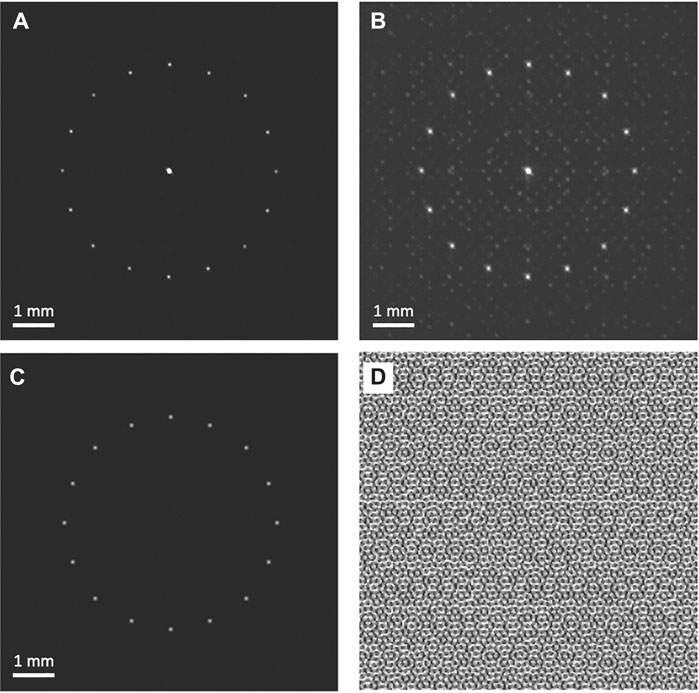
FIGURE 1. The Unmodulated Light focuses to a central bright spot and ghost patterns are formed due to diffraction from the SLM. (A) Intensity pattern from the conventional beam path captured by an sCMOS camera that is, positioned in the object plane. The unmodulated light is focused at the center of the field of view (FOV) by the objective lens creating an undesired central focal point. (B) intensity-adjusted representation of A highlighting ghost patterns. (C, D) Target intensity pattern and its corresponding phase mask.
Spatial filters are commonly used to block the 0th order light at the point in the light path where it first comes to focus [17, 31]. However, because 0th order (unmodulated) and 1st order (modulated) light come into focus in the same plane, it is not possible to block one without the other, i.e., it is not possible to generate points within the blocked region.
Optical designs that are based on higher order diffraction can be used to achieve complete blocking of the unmodulated light without having an inaccessible central region [32–34]. However, such designs require filtering out unmodulated light using a slit, which cuts the SLM field of view in half of its original size for binary SLMs. Moreover, less laser power is transmitted through higher order diffraction patterns. Grating-based methods have been developed that utilize SLMs capable of modulating to 4π phase delay, to simultaneously modulate for two phase masks in order to remove the replicated higher orders as well as the 0th order [35]. However, the accessibility of these techniques is somewhat limited due to the popularity of SLMs with a maximum phase modulation of 2π.
Removing the 0th order from the object plane by axially shifting the focus of the unmodulated light has been suggested using a slightly converging incident beam on the SLM. The modulated light is shaped by the SLM into collimated beam, which focuses in the object plane, whereas the unmodulated beam is focused above the object plane [30]. However, this configuration has limitations. First, because the unmodulated light comes into focus above the object plane, the sample thickness is limited in this approach. Second, because a beam block is implemented in a plane where the modulated light is not collimated, both the phase and amplitude information from the modulated light is obstructed. This results in partially occluded intensity patterns. An alternative approach to limit 0th order light is through computational removal [36]. This method, which requires calculating a hologram that superimposes and cancels the unwanted intensity, is simple to implement from a hardware perspective, but requires complete characterization of the amplitude and phase components of the 0th order beam, which is unique to each pattern imposed on the SLM.
Here we address the problem of imperfections and inaccessible regions using a modified beam path with a “virtual” lens added to the calculated holographic pattern which replaces one of the real lenses in the system in the Fourier plane of the incident light. In addition, we show the use of such a configuration in a two-photon application with our custom built two-photon microscope.
Optical Design
To decouple the focal planes of the unmodulated and modulated light, we added an additional focusing lens to the diffraction pattern programmed into the SLM. The SLM is thus programmed to display a modular sum of two phase modulations: the phase-mask corresponding to the target intensity pattern and a Fresnel lens. Since only the modulated light is affected by the virtual lens, the beam path is configured such that the modulated light focuses in the Fourier plane of the unmodulated light, and the unmodulated light focuses in the Fourier plane of the modulated light.
To compare this novel optical configuration with the conventional configuration we set up a system with optical paths for the conventional and the virtual lens configurations (Figure 2A). The beam path in cyan shows the conventional configuration and the beam path in magenta shows our virtual lens configuration. The two beam paths were set up to have an identical layout, except that the conventional beam path uses a real lens, L3, after the SLM instead of the virtual lens phase-mask displayed on the SLM (Holoeye LC-R 2500) which was used for the virtual lens beam path. In the conventional beam path, L3 and L4 are placed with a 4-F configuration to image the phase mask containing the phase information in the back focal plane of the imaging lens (L5). A similar 4F configuration is obtained in the virtual-lens path, by using the virtual-lens and L6 couple. As illustrated in Figure 2, the SLM surface projecting the virtual lens is positioned at a Fvl + FL6 distance from L6. The conjugated phase mask plane forms at the back focal plane of the imaging lens (L7). Additionally, in the conventional beam path, L3 is placed at its focal length from the SLM and L4 and L5 are placed in 4-F configuration with respect to the intermediate image and object planes to maximize the pupil of the lens system. In the virtual lens beam path, L6 and L7 are placed in 4-F configuration with respect to the intermediate image and object planes so that they play the same role as L4 and L5. For consistency between the two beam paths, L6 and L4 were both chosen to have a nominal focal length of 400 mm and L7 and L5 were both chosen to have a nominal focal length of 500 mm. The focal length of the virtual lens displayed on the SLM was set equal to the nominal focal length of L3, which was 400 mm because the virtual lens and L3 both serve the same function.
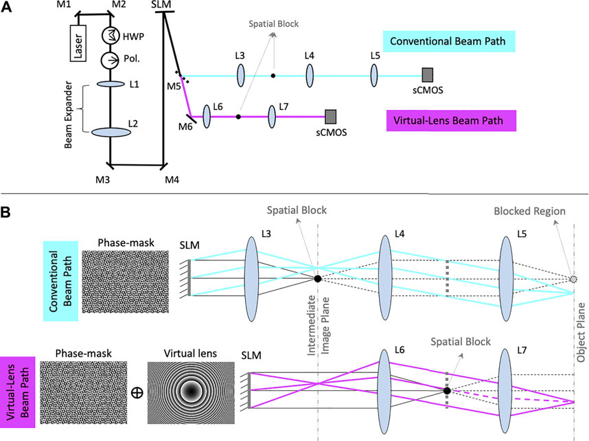
FIGURE 2. Details of the optical path and lens arrangement. (A) Optical layout for comparison of the conventional and virtual lens configuration. M1 and M2 are mirrors that steer the beam into the system. The half wave plate (HWP) and polarizer (Pol.) work in concert to pass light to the SLM at its designed polarity. The set of L1 and L2 lenses expand the beam to fill the SLM. M3 and M4 center the beam on the SLM. M5 is a removable mirror that, when in place, reflects the beam to the conventional beam path (cyan) and when removed, allows the beam to pass to the virtual lens beam path (magenta). L3, L4, and L5 are the sequence of lenses that project the illumination pattern on the sCMOS camera on the conventional path, M6 is the mirror that in absence of M5 reflects the beam into the virtual lens beam path and L6 and L7 are the sequence of lenses required to project the illumination pattern on the sCMOS camera. The spatial blocks are placed on the optical axes in the front focal planes of lenses L3 and L6. (B) the ray diagram of the conventional (cyan) and virtual lens (magenta) configurations. The phase masks displayed on the SLM are shown on the left.
Figure 2B shows ray diagrams for each of the two beam paths. The unmodulated light is represented in black while the modulated light is shown in cyan in the conventional beam path and magenta in the virtual lens beam path. In the conventional configuration, the unmodulated light focuses to a bright point along the optical axis in the object plane. Traditionally, a spatial block is used at the center of the intermediate image plane to remove this 0th order point. This spatial block also prevents the modulated light from reaching the center of the image plane (dashed lines). Alignment is performed in a similar fashion as traditional lens alignment. A virtual lens is projected onto the surface of the SLM and L6 is added such that the focal lengths of the SLM and L6 coincide. Collimation can be checked using a shearing interferometer, and fine adjustments can be made by shifting L6 back and forth on an optical table to achieve collimation. A similar effect can also be achieved by changing the focal length of the virtual lens displayed.
The outline of the formed image in the object plane can be traced by an example ray diagram in cyan. The ray diagram for the unmodulated light is shown in gray. Note that the central portion of this image is obstructed due to the use of the spatial block. In the virtual lens beam path, however, the unmodulated light is decoupled from the modulated light and instead of coming into focus as a bright central spot, it is collimated in the intermediate image plane, forming a dim Gaussian background intensity. The ray diagram of the unmodulated light is shown in gray. To remove this background from the object plane, a spatial block with (D = 3 mm) can be positioned in the focal plane of L6 (intermediate image plane) where the unmodulated light comes to focus. However, since the modulated light is collimated in this plane and carries only the phase information, the image formed in the object plane remains intact. Subsequently, the field of view of the SLM remains fully accessible. The ray diagram in magenta shows the outline of the resulting image formed in the object plane. As illustrated in the diagram, in contrast to the conventional beam path, the central portion of the image is not blocked.
In order to decouple the two intermediate image planes for unmodulated and modulated light, the SLM displays a modular sum of two phase modulations: the phase-mask computed with the Gerchberg-Saxton algorithm applied to the target intensity pattern and a phase-modulation of a convex lens with a focal length equal to that of L3 (
Results
Virtual Lens Makes the Full Field of View Accessible for SLM Optical Stimulation
First we verified the expected effects of the conventional and virtual lens beam paths on the accessibility of the field of view using a Cartesian axis intensity pattern (Figure 3A) generated by the phase mask in Figure 3B. Figures 3C,D show images of the generated intensity captured at the object planes of the conventional configuration (Figure 3C) and virtual lens configuration (Figure 3D) without a spatial block. As expected, the unmodulated light focuses to a point at the center of the image plane in the conventional configuration, while in the virtual lens configuration the unmodulated light has a wide low-intensity Gaussian profile proportional to the light intensity profile of the expanded and collimated laser beam. Figures 3E,F show both configurations with a spatial block. In the conventional configuration light is blocked in a region around the center whose width is proportional to the size of the beam blocker. In the virtual lens configuration, the pattern has uniform brightness, demonstrating that uniform accessibility of the whole field of view is achieved.
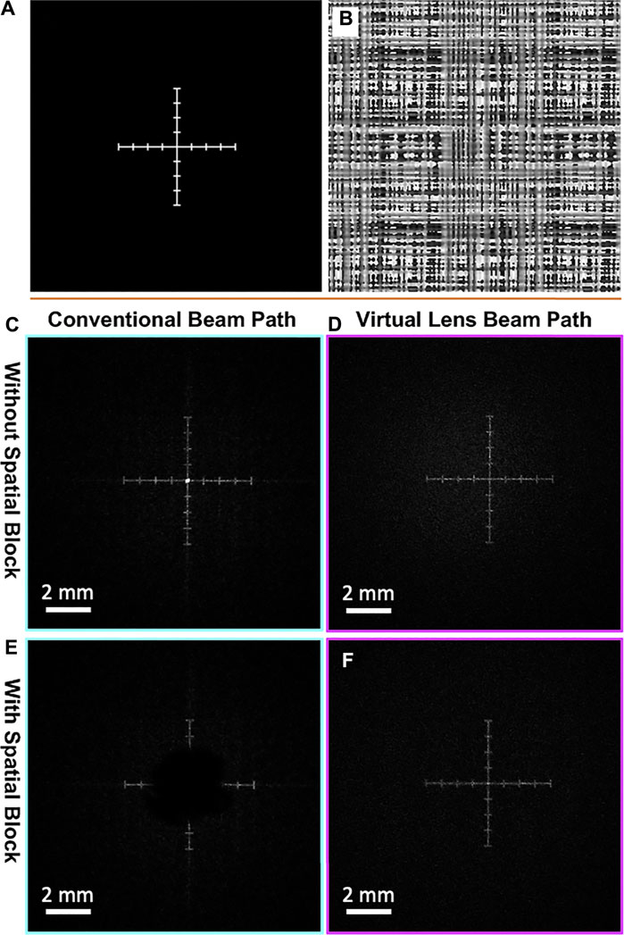
FIGURE 3. Comparing intensity patterns between conventional and virtual lens beam paths. (A) The target intensity pattern for a Cartesian axis. (B) The corresponding phase mask. (C–F) The resulting intensity patterns seen by the camera in each beam path in the presence or absence of a spatial block for the beam paths. (C) The unmodulated light focuses into a bright central spot in the conventional path without a spatial block. (D) The unmodulated light does not come into focus anywhere after the imaging lens in the virtual lens beam path and creates a very dim Gaussian background intensity. (E) Using a spatial block in the conventional path removes information from the center of the FOV, making it inaccessible for photo-stimulation. (F) Using a spatial block in the virtual lens beam path removes the background Gaussian intensity generated by the unmodulated light, while keeping the entire FOV accessible.
Virtual Lens Beam Path Increases Fidelity of Target Points
To compare the intensity pattern generated by the SLM in each beam path, we used an eleven-by-eleven matrix of points as a target illumination pattern. In order to ensure that differences in the SLM-generated intensity patterns from each path are only due to the difference in their optical configurations, spatial filters for blocking the zeroth order of diffraction were not used in either path. A revised version of the Crocker-Grier object-finding algorithm was used to locate the target illumination points in each image. The integrated intensity and standard deviations in major axis lengths were calculated for each generated point and compared between the two beam paths.
Figure 4A and Figure 4B show the SLM generated patterns for the conventional and virtual lens beam paths respectively. A logarithmic adjustment was applied to the intensity map. To compare the quality of the points generated by each path, the width of each point was quantified by fitting its intensity profile to a 2-dimensional Gaussian and registering their widths (σx and, σy). The average image of the points in the conventional beam path (excluding the 0th order) and the virtual lens beam path is shown in Figure 4C (right and left images respectively). Figure 4D shows the distribution of the 2D standard deviation for all generated points. The results indicate that the use of the virtual lens configuration leads to comparably sized points to their counterparts from the conventional beam path, despite the suboptimal Fresnel lens formed by the pixelated array of the SLM. Of note, however, is the increased variance in focal point size in the virtual lens configuration. This could be caused by a modulated point spread function due to a more limited opening angle of the light cone produced by the SLM, an effect induced by the imposition of the lens function [37].
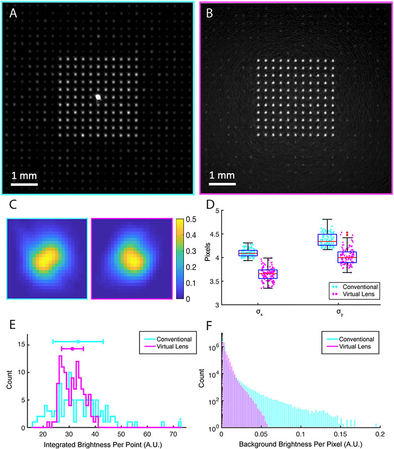
FIGURE 4. Quantification of the fidelity of reconstruction of an array of points by the conventional and virtual paths (A) The intensity pattern generated at the object plane in an array of eleven-by-eleven points captured by the camera in the conventional beam path and (B) the virtual lens beam path. (C) The averaged intensity heat map of the SLM generated points created in the conventional (right) and the virtual lens beam path (left). (D) The distribution of standard deviation for a fitted 2D Gaussian to each of the generated points in their orthogonal axes. (E) The integrated intensity distribution of the generated points in the conventional beam path and the virtual lens beam path. (F) Background intensity distribution (per pixel) for virtual lens beam path, and the conventional beam path excluding the 0th order.
In photo-stimulation applications in neuroscience, uniformity in size is less important due to irregularities in the shape and size of neurons, but uniformity in intensity is of particular importance, due to a desire for low variance in induced photocurrent across multiple channels. Figure 4E shows the histograms of the integrated intensity of all pixels above a fixed threshold in each extracted point. This fixed threshold in turn is set by the general size of the reconstructed points and is the same for the conventional beam path and the virtual lens beam path. The standard deviation of the intensities generated is 29% of the mean intensity in the conventional beam path and 13% in the virtual lens beam path (p = 0.025). Therefore, while the points in the conventional and virtual paths have similar mean intensities, the latter are more uniform.
Virtual Lens Creates Fewer and Lower Intensity Ghost Patterns
Another benefit of the virtual lens beam path is its ability to remove undesired ghost patterns from the object plane by displacing them axially into other focal planes. In order to visualize these speckles, Figures 4A,B show examples of the array of points image from the conventional beam path (A) and the virtual lens beam path (B). A logarithmic adjustment was applied to the intensity map. These ghost patterns contribute to the background intensity and they are problematic for precise photo-stimulation as they deliver light to arbitrary locations of the field of view. To demonstrate how these ghost patterns contribute to the background intensity, Figure 4F shows the histogram of the background intensity for the conventional beam path and the virtual lens beam path. The virtual lens beam path yields dimmer background intensity despite having the unfocused unmodulated light in the background. Using a block for the unmodulated light can further reduce this background intensity.
To locate and quantify the ghost patterns in the previously shown dot matrix pattern, features were extracted for a fixed low threshold for the conventional and virtual lens beam path. A total of 607 ghost features were found in the conventional beam path whereas only 72 features were found for the virtual lens beam path. Moreover, to have a measure for the signal to noise ratio (SNR) in both beam paths, we calculated the ratio of the dimmest target point to the brightest ghost feature for both paths. The SNR for the conventional beam path is 1.21 and for the virtual lens beam path is 8.8. Thus, not only does the virtual lens path yield fewer ghost patterns, but it also reduces the peak intensity of the ghost patterns. Since the formation of ghost patterns is dependent on the symmetry of the target intensity pattern, we also measured the ghost pattern intensity for a ring of points, which has a different symmetry than the previous pattern. Using the same threshold as before, 71 ghost features were extracted in the conventional beam path. However, only 25 ghost points were extracted in the virtual lens beam path. The dimmest point was significantly brighter than the brightest ghost pattern for this ring arrangement of points, with the signal to noise ratio of the two at 21.72 and 26.72 respectively for the conventional and the virtual lens beam paths.
Validation of the Virtual Lens Configuration in Two-Photon Application
We have adopted the virtual lens configuration in a custom built two-photon microscope. This microscope consists of one upright microscope (Sutter Instruments) and one inverted microscope that both focus on the same object plane as illustrated in Figure 5A. The virtual lens path uses a Boulder Nonlinear Systems 1536 × 1536 SLM. The system also has a second path that uses a galvo-resonant pair for two photon imaging. No 0th order blocker is used in our two-photon microscope. The bottom inverted microscope, shown below the sample plane in Figures 5A, is a Nikon TE200 with additional motorized stage and focus drive, connected to a Hamamatsu ImagEM X2 EMCCD set up to perform epifluorescence microscopy and to collect the fluorescent emission from the sample. The camera is equipped with a filter that blocks the 1040 nm illumination (Thorlabs FESH1000). For this demonstration we are using a 20X Olympus Objective with 1.00 NA (XLUMPLFLN20XW) for the top microscope and a 25X Olympus objective with 1.05 NA (XLPLN25XWMP2) for the bottom microscope.
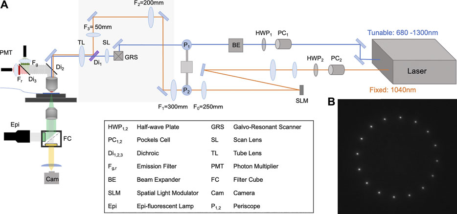
FIGURE 5. Two-photon optical layout and result (A) Schematic of the optical layout for two-photon photo-stimulation and imaging. The two-photon photo-stimulation path uses the fixed output of the laser (Coherent Chameleon Discovery), shown in orange, and is shaped by a BNS 1536 × 1536 SLM in a virtual-lens configuration with an Fvl = 600 mm. The two-photon imaging path that uses the tunable output of the laser is shown in blue and is scanned by a galvo-resonant pair (GRS). The two beams are combined by a notch dichroic (Di1, Semrock NFD01-1040) before entering the objective. The bottom inverted microscope, shown below the sample plane, is a Nikon TE200 with additional motorized stage and focus drive, connected to a Hamamatsu ImagEM X2 EMCCD, collects the fluorescent light. Note that there is no 0th order block in this layout. (B) The two-photon image formed by the SLM captured by the inverted microscope. Only the intended target points are generated by the two-photon excitation.
In this system we are able to demonstrate that a virtual lens configuration is compatible with two-photon excitation. A long focal distance virtual lens (Fvl = 600 mm) is used for two reasons: First, a longer focal distance lens leads to Fresnel fringes that are spaced further apart, limiting the interference with the added phase mask. Second, the higher order diffraction patterns generated by the weaker Fresnel virtual lens will become further spaced apart axially from the first order of diffraction. To show the two-photon excitation capability of the photo-stimulation path we used a thin, uniform fluorescent sample made by a droplet of 2 mM X-Rhod-1, AM dye in 100% dimethyl sulfoxide (DMSO), sandwiched between two No. 1.5 coverslips in the object plane. We illuminate the sample with a 1040 nm laser modulated with a superposition of a virtual lens and a phase mask that produces a ring of 16 focal points. A sample image of the ring of points as captured by the camera is shown in Figure 5B. This result shows that even in the absence of a spatial block, only the intended target points generate two-photon fluorescence. This demonstrates the suitability of our virtual lens configuration to neuroscience photo-stimulation experiments utilizing two-photon excitation principles [38, 39].
Additionally, while ghost patterns are still formed, they occur in deeper planes and thus have reduced impact in many experimental settings, especially those in neuroscience, due to additional absorption and scattering. Below, we demonstrate this axial displacement of the ghost patterns, created by the second order of diffraction, with respect to the target pattern (Figure 6). Figure 6A shows the target pattern at the object plane (Z = 0 μm). The objective is then moved away from the sample until the second order of diffraction comes into focus at Z = 40 μm (Figure 6B). To compare the intensities created in each point, the peak intensity from each point is extracted. Figure 6C shows the distribution of the peak intensities. The first order of diffraction is shown to be approximately 4-fold more intense than the points comprising the second order ghost pattern.
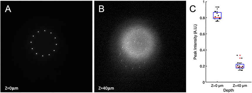
FIGURE 6. Two photon images of first and second order diffracted light. A thin fluorescent sample is used, sitting at the object plane of both the bottom and top objectives. (A) The first order of diffraction forms at the object plane. (B) The top objective is moved axially away from the sample by 40 μm where the second order pattern is formed. (C) The distribution of peak intensity at each point.
Discussion
Holographic multiphoton stimulation of multiple neurons is emerging as a powerful technique to understand and modulate the operation of the brain. Spatial light modulators are capable of splitting a single laser beam into multiple points, and optogenetics leverages this capability for targeted activation of multiple neurons. Since information flows through interconnected networks of neurons, the ability to selectively activate groups of neurons is critical for understanding brain function. In this work, we have introduced a virtual lens configuration that addresses several limitations of widely used SLM approaches.
First, we separate the focal planes of the unmodulated light from the modulated light such that the unmodulated light focuses in the Fourier plane of the modulated light. This provides significant benefits for studies involving optical stimulation of the brain. The entire field of view in the object plane remains accessible for optical stimulation, and the unmodulated light can be removed without substantial information loss by a spatial block positioned after the first physical lens. This new capability is critical when aiming to stimulate neurons in vivo, as targeted neurons may be located anywhere in the field of view. Furthermore, it is possible to remove the spatial block without generating a high intensity 0th order focal point anywhere in the sample volume (the region after L7) since the unmodulated light is collimated after L7.
This configuration also improved the uniformity of the targeted points in the field of view. Moreover, we show that the size and shape of the points generated in both paths remain comparable despite the use of a more complex phase modulation in the virtual lens beam path. We also show that our configuration can reduce the number of “ghost patterns” associated with the phase-only property of the utilized SLM. In the conventional configuration the intensity of these ghost patterns can become comparable to the intensity of the targeted patterns for certain pattern symmetries. We show that the ghost patterns created are fewer in quantity when using a virtual lens. These advantages of the virtual lens configuration are essential for photo-stimulation as it expands to target multiple neurons simultaneously in deep layers of the brain.
The increased uniformity will support targeting each neuron in a group with comparable probability, while the reduction of ghost patterns will lower the probability of stimulating non-targeted neurons.
Finally, we show that in two-photon applications, due to the quadratic dependence of absorption probability on light, the unmodulated light will not need to be blocked because it remains unfocused in the imaging volume. This advantage will be most significant for high power lasers that are prone to damaging the beam blocker. It should be noted that shorter focal lengths of the virtual lens may limit the maximum possible lateral deviation and limit the intensity of points far from the optical axis created by the SLM. The strength of the effect increases with numerical aperture of the objective and decreases with increasing resolution of the SLM [37, 40]. However, this effect should be relatively negligible at the long focal lengths typically used in two-photon fluorescence microscopy applications.
The virtual lens phase mask has a diffraction efficiency function consisting of a set of on-axis lenses with focal lengths
One additional caveat is dispersion when the virtual lens configuration is used e.g., with ultra-fast lasers in multiphoton applications. The SLM diffraction is wavelength dependent, and thus the virtual lens will focus light with some axial separation by wavelength (worse than what can be achieved with dispersion compensated lenses) [37]. The strength of this effect is inversely related to the pulse width of the laser used and will be most apparent with ultrashort and supercontinuum lasers. This effect could be harnessed for temporal focusing, when used with a static diffraction grating [46].
The virtual lens configuration introduced here only requires small changes to hardware and software. On the optics hardware side, the virtual lens configuration requires the removal of one lens, the corresponding shortening of the beam path, and allows for the removal of the beam blocker for unmodulated light. On the software side the virtual lens configuration entails a change in the calculation of the SLM phase pattern to include a virtual lens. Both changes are straightforward to implement and thus these powerful benefits should be accessible to users of many commercial systems in the field of neuroscience.
Data Availability Statement
The raw data supporting the conclusion of this article will be made available by the authors, without undue reservation.
Author Contributions
SA designed the single photon and two-photon photo-stimulation optical setup, led analysis effort and drafted the manuscript. SA and PA co-designed and built the custom two-photon microscope. MW carried out the single photon experiments and contributed to analysis and drafting the manuscript. GAF contributed to workflow design, WL designed the experiment and analysis workflow and edited the manuscript.
Funding
Work supported by the BRAIN initiative grants U01NS090569 and 1U19NS107464.
Conflict of Interest
The authors declare that the research was conducted in the absence of any commercial or financial relationships that could be construed as a potential conflict of interest.
Publisher’s Note
All claims expressed in this article are solely those of the authors and do not necessarily represent those of their affiliated organizations, or those of the publisher, the editors and the reviewers. Any product that may be evaluated in this article, or claim that may be made by its manufacturer, is not guaranteed or endorsed by the publisher.
References
1. Chalasani SH, Chronis N, Tsunozaki M, Gray JM, Ramot D, Goodman MB, et al. Dissecting a Circuit for Olfactory Behaviour in Caenorhabditis elegans. Nature (2007) 450(7166):63–70. doi:10.1038/nature06292
2. Dombeck DA, Harvey CD, Tian L, Looger LL, Tank DW. Functional Imaging of Hippocampal Place Cells at Cellular Resolution During Virtual Navigation. Nat Neurosci (2010) 13(11):1433–40. doi:10.1038/nn.2648
3. Fletcher ML, Masurkar AV, Xing J, Imamura F, Xiong W, Nagayama S, et al. Optical Imaging of Postsynaptic Odor Representation in the Glomerular Layer of the Mouse Olfactory Bulb. J Neurophysiol (2009) 102(2):817–30. doi:10.1152/jn.00020.2009
4. Wang JW, Wong AM, Flores J, Vosshall LB, Axel R. Two-Photon Calcium Imaging Reveals an Odor-Evoked Map of Activity in the Fly Brain. Cell (2003) 112(2):271–82. doi:10.1016/s0092-8674(03)00004-7
5. Sherafati A, Hassanpour MS, Dwyer N, Fishell AK, Eggebrecht AT, Firszt JB, et al. Optical Neuroimaging of Speech Perception in Listeners with Cochlear Implants. In: Biophotonics Congress: Biomedical Optics 2020 (Translational, Microscopy, OCT, OTS, BRAIN) (2020). doi:10.1364/brain.2020.bm4c.4
6. Fishell AK, Arbeláez AM, Valdés CP, Burns-Yocum TM, Sherafati A, Richter EJ, et al. Portable, Field-Based Neuroimaging Using High-Density Diffuse Optical Tomography. Neuroimage (2020) 215:116541. doi:10.1016/j.neuroimage.2020.116541
7. Miesenböck G, Kevrekidis IG. Optical Imaging and Control of Genetically Designated Neurons in Functioning Circuits. Annu Rev Neurosci (2005) 28:533–63. doi:10.1146/annurev.neuro.28.051804.101610
8. Nagel G, Brauner M, Liewald JF, Adeishvili N, Bamberg E, Gottschalk A. Light Activation of Channelrhodopsin-2 in Excitable Cells of Caenorhabditis elegans Triggers Rapid Behavioral Responses. Curr Biol (2005) 15(24):2279–84. doi:10.1016/j.cub.2005.11.032
9. Boyden ES, Zhang F, Bamberg E, Nagel G, Deisseroth K. Millisecond-timescale, Genetically Targeted Optical Control of Neural Activity. Nat Neurosci (2005) 8(9):1263–8. doi:10.1038/nn1525
10. Hirase H, Nikolenko V, Goldberg JH, Yuste R. Multiphoton Stimulation of Neurons. J Neurobiol (2002) 51(3):237–47. doi:10.1002/neu.10056
11. Huber D, Petreanu L, Ghitani N, Ranade S, Hromádka T, Mainen Z, et al. Sparse Optical Microstimulation in Barrel Cortex Drives Learned Behaviour in Freely Moving Mice. Nature (2008) 451(7174):61–4. doi:10.1038/nature06445
12. Chong E, Moroni M, Wilson C, Shoham S, Panzeri S, Rinberg D. Manipulating Synthetic Optogenetic Odors Reveals the Coding Logic of Olfactory Perception. Science (2020) 368(6497):eaba2357. doi:10.1126/science.aba2357
13. Wang S, Szobota S, Wang Y, Volgraf M, Liu Z, Sun C, et al. All Optical Interface for Parallel, Remote, and Spatiotemporal Control of Neuronal Activity. Nano Lett (2007) 7(12):3859–63. doi:10.1021/nl072783t
14. Baier H, Scott EK. Genetic and Optical Targeting of Neural Circuits and Behavior-Zebrafish in the Spotlight. Curr Opin Neurobiol (2009) 19(5):553–60. doi:10.1016/j.conb.2009.08.001
15. Leifer AM, Fang-Yen C, Gershow M, Alkema MJ, Samuel ADT. Optogenetic Manipulation of Neural Activity in Freely Moving Caenorhabditis elegans. Nat Methods (2011) 8(2):147–52. doi:10.1038/nmeth.1554
16. Helmchen F, Denk W. Deep Tissue Two-Photon Microscopy. Nat Methods (2005) 2(12):932–40. doi:10.1038/nmeth818
17. Nikolenko V, Watson BO, Araya R, Woodruff A, Peterka DS, Yuste R. SLM Microscopy: Scanless Two-Photon Imaging and Photostimulation with Spatial Light Modulators. Front Neural Circuits (2008) 2:5. doi:10.3389/neuro.04.005.2008
18. Packer AM, Russell LE, Dalgleish HWP, Häusser M. Simultaneous All-Optical Manipulation and Recording of Neural Circuit Activity with Cellular Resolution In Vivo. Nat Methods (2015) 12(2):140–6. doi:10.1038/nmeth.3217
19. Chen I-W, Papagiakoumou E, Emiliani V. Towards Circuit Optogenetics. Curr Opin Neurobiol (2018) 50:179–89. doi:10.1016/j.conb.2018.03.008
20. Marshel JH, Kim YS, Machado TA, Quirin S, Benson B, Kadmon J, et al. Cortical Layer-Specific Critical Dynamics Triggering Perception. Science (2019) 365(6453):eaaw5202. doi:10.1126/science.aaw5202
21. Forli A, Vecchia D, Binini N, Succol F, Bovetti S, Moretti C, et al. Two-Photon Bidirectional Control and Imaging of Neuronal Excitability with High Spatial Resolution In Vivo. Cel Rep (2018) 22(11):3087–98. doi:10.1016/j.celrep.2018.02.063
22. Carrillo-Reid L, Han S, Yang W, Akrouh A, Yuste R. Controlling Visually Guided Behavior by Holographic Recalling of Cortical Ensembles. Cell (2019) 178(2):447–57. doi:10.1016/j.cell.2019.05.045
23. Dal Maschio M, De Stasi AM, Benfenati F, Fellin T. Three-Dimensional In Vivo Scanning Microscopy with Inertia-Free Focus Control. Opt Lett (2011) 36(17):3503–5. doi:10.1364/ol.36.003503
24. Curtis JE, Koss BA, Grier DG. Dynamic Holographic Optical Tweezers. Opt Commun (2002) 207(1):169–75. doi:10.1016/s0030-4018(02)01524-9
25. Zhang Z, You Z, Chu D. Fundamentals of Phase-Only Liquid crystal on Silicon (LCOS) Devices. Light Sci Appl (2014) 3:e213. doi:10.1038/lsa.2014.94
26. Toyoda H, Inoue T, Hara T. Application of Liquid crystal on Silicon Spatial Light Modulator (LCOS-SLM) for Manipulation and Sensing. In: 2015 14th Workshop on Information Optics (WIO). IEEE (2015). doi:10.1109/wio.2015.7206900
27. Banerjee AG, Chowdhury S, Losert W, Gupta SK. Survey on Indirect Optical Manipulation of Cells, Nucleic Acids, and Motor Proteins. J Biomed Opt (2011) 16(5):051302. doi:10.1117/1.3579200
28. Lee S-H, Grier DG. Robustness of Holographic Optical Traps against Phase Scaling Errors. Opt Express (2005) 13(19):7458–65. doi:10.1364/opex.13.007458
29. Hesseling C, Woerdemann M, Hermerschmidt A, Denz C. Controlling Ghost Traps in Holographic Optical Tweezers. Opt Lett (2011) 36(18):3657–9. doi:10.1364/ol.36.003657
30. Polin M, Ladavac K, Lee S-H, Roichman Y, Grier DG. Optimized Holographic Optical Traps. Opt Express (2005) 13(15):5831–45. doi:10.1364/opex.13.005831
31. Paluch-Siegler S, Mayblum T, Dana H, Brosh I, Gefen I, Shoham S. All-Optical Bidirectional Neural Interfacing Using Hybrid Multiphoton Holographic Optogenetic Stimulation. Neurophoton (2015) 2(3):031208. doi:10.1117/1.nph.2.3.031208
32. Golan L, Reutsky I, Farah N, Shoham S. Design and Characteristics of Holographic Neural Photo-Stimulation Systems. J Neural Eng (2009) 6(6):066004. doi:10.1088/1741-2560/6/6/066004
33. Matar S, Golan L, Farah N, Reutsky I, Shoham S. Holographic Photo-Stimulation for Dynamic Control of Neuronal Population Activity. In: 2009 4th International IEEE/EMBS Conference on Neural Engineering (2009). p. 84–7. doi:10.1109/ner.2009.5109240
34. Farah N, Zoubi A, Matar S, Golan L, Marom A, Butson CR, et al. Holographically Patterned Activation Using Photo-Absorber Induced Neural-Thermal Stimulation. J Neural Eng (2013) 10(5):056004. doi:10.1088/1741-2560/10/5/056004
35. Jesacher A, Bernet S, Ritsch-Marte M. Broadband Suppression of the Zero Diffraction Order of an SLM Using its Extended Phase Modulation Range. Opt Express (2014) 22(14):17590–9. doi:10.1364/oe.22.017590
36. Palima D, Daria VR. Holographic Projection of Arbitrary Light Patterns with a Suppressed Zero-Order Beam. Appl Opt (2007) 46(20):4197–201. doi:10.1364/ao.46.004197
37. Jesacher A, Roider C, Ritsch-Marte M. Enhancing Diffractive Multi-Plane Microscopy Using Colored Illumination. Opt Express (2013) 21(9):11150–61. doi:10.1364/oe.21.011150
38. Ronzitti E, Ventalon C, Canepari M, Forget BC, Papagiakoumou E, Emiliani V. Recent Advances in Patterned Photostimulation for Optogenetics. J Opt (2017) 19(11):113001. doi:10.1088/2040-8986/aa8299
39. Bovetti S, Moretti C, Fellin T. Patterned Two-Photon Illumination for High-Speed Functional Imaging of Brain Networks In Vivo. In: Advanced Optical Methods for Brain Imaging. Springer (2019). p. 123–41. doi:10.1007/978-981-10-9020-2_7
40. Salter PS, Iqbal Z, Booth MJ. Analysis of the Three-Dimensional Focal Positioning Capability of Adaptive Optic Elements. Int J Optomechatronics (2013) 7(1):1–14. doi:10.1080/15599612.2012.758791
41. Moreno I, Márquez A, Iemmi C, Campos J, Yzuel MJ. Modulation Diffraction Efficiency of Spatial Light Modulators. In: 2011 10th Euro-American Workshop on Information Optics. IEEE (2011). doi:10.1109/wio.2011.5981461
42. Hazra LN, Delisle CA. Higher Order Kinoform Lenses: Diffraction Efficiency and Aberrational Properties. Opt Eng (1997) 36(5):1500–7. doi:10.1117/1.601375
43. Theer P, Denk W. On the Fundamental Imaging-Depth Limit in Two-Photon Microscopy. J Opt Soc Am A (2006) 23(12):3139–49. doi:10.1364/josaa.23.003139
44. Ying J, Liu F, Alfano RR. Spatial Distribution of Two-Photon-Excited Fluorescence in Scattering media. Appl Opt (1999) 38(1):224–9. doi:10.1364/ao.38.000224
45. Oheim M, Beaurepaire E, Chaigneau E, Mertz J, Charpak S. Two-Photon Microscopy in Brain Tissue: Parameters Influencing the Imaging Depth. J Neurosci Methods (2001) 111(1):29–37. doi:10.1016/s0165-0270(01)00438-1
Keywords: holographic photo-stimulation, SLM microscopy, optics, optogenetics, neuroscience
Citation: Aghayee S, Weikert M, Alvarez P, Frank GA and Losert W (2021) High Fidelity Spatial Light Modulator Configuration for Photo-Stimulation. Front. Phys. 9:587112. doi: 10.3389/fphy.2021.587112
Received: 24 July 2020; Accepted: 10 August 2021;
Published: 01 September 2021.
Edited by:
Halina Rubinsztein-Dunlop, The University of Queensland, AustraliaReviewed by:
Darcy S. Peterka, Columbia University, United StatesAlexander B. Stilgoe, The University of Queensland, Australia
Copyright © 2021 Aghayee, Weikert, Alvarez, Frank and Losert. This is an open-access article distributed under the terms of the Creative Commons Attribution License (CC BY). The use, distribution or reproduction in other forums is permitted, provided the original author(s) and the copyright owner(s) are credited and that the original publication in this journal is cited, in accordance with accepted academic practice. No use, distribution or reproduction is permitted which does not comply with these terms.
*Correspondence: Wolfgang Losert, d2xvc2VydEB1bWQuZWR1