 Markus Königshofer
 Martin Stoiber1,2
 Ewald Unger
 Francesco Moscato
- 1Center for Medical Physics and Biomedical Engineering, Medical University of Vienna, Vienna, Austria
- 2Ludwig Boltzmann Institute for Cardiovascular Research, Vienna, Austria
Additive manufacturing machines, based on the multimaterial jetting technology, are widely used for three-dimensional (3D) printing of sophisticated medical models, which are aimed to be used for preoperative planning and surgical training. Gaining knowledge of process-related influences on mechanical and dimensional properties of 3D-printed parts makes up an essential basis for the design and manufacture of medical models. There are few studies on characterization of multimaterial parts, and those are limited to tests that are not based on standardized methods. Within the scope of this work, mechanical and dimensional investigations were performed on multimaterial parts that were printed using an Objet500–Connex3 3D printer (Stratasys Ltd., Minnesota, Eden Prairie, MN, USA). Among test methods listed in DIN EN ISO 17296-3, tensile tests were chosen for mechanical characterization. In the tensile tests, combinations of four different materials (Tango+, VeroClear, VeroPureWhite, MED610) were tested in three build orientations (XY, YX, ZX). To investigate the orientation-dependent printing accuracy, the tensile specimens were further checked for their dimensional accuracy. Statistically significant variations in the mechanical properties were found between different orientation levels. In general, specimens printed in XY orientation show higher tensile strength than YX- and ZX-oriented specimens. The tensile moduli determined are in the range from 0.2 to 2,500 MPa and compare well with the tensile moduli found in soft biological tissues. Dimensional deviations were found highest for the length of ZX-oriented tensile specimens. For this orientation level, it could be observed that multimaterial specimens, which contain higher percentage of the soft material Tango+, are characterized by higher shrinkage. For tensile specimens printed from the pure photopolymer Tango+, a shrinkage of 4.6% in length was determined. In summary, it was found that with multimaterial jetting technology, the increased shrinkage and lower mechanical strength in the ZX direction must be considered in the design process.
Introduction
Applications of additive manufacturing (AM) technologies have quickly expanded from the field of traditional engineering to the field of medicine. The flexibility provided by AM enables surgeons to determine the most appropriate implant for each patient and to adapt and optimize the device design before surgery. This improves the performance of implants, lowers the risk of surgical complications, and reduces the duration of the surgery by eliminating the need for implant adjustments during intervention [1].
Moreover, AM allows the production of complex patient-specific medical models that are based on medical imaging data. AM medical models help doctors to better understand details of the patients' anatomy and the topographical relationship of anatomic structures and thus enhance knowledge and allow surgical training for specific treatments. In cardiovascular research, material jetting is one of the most widely applied AM technologies. This technology enables the production of colored and flexible structures. Medical models printed from flexible materials are especially suitable for planning implantation procedures of medical devices and allow practicing of surgical stitches and cuts. In addition, flexible materials provide possibilities to mimic the compliance of vessels. Because of the differences in mechanical properties of human tissue and polymeric plastics, implementation of cardiovascular models remains difficult, wherein the compliance can be varied over the wall thickness of the vessels [2]. New possibilities for mimicking more complex mechanical structures arise from combining different materials in one build procedure, made possible by, e.g., multimaterial jetting technology.
Available material property specifications, provided by manufacturers, are specified in broad ranges, and influencing factors of the material jetting process (e.g., the anisotropy due to layer-wise build procedure) are not completely understood [3]. Furthermore, the lack of existing standards for characterization of AM processes, e.g., for characterization of the mechanical behavior of multimaterial jetted parts [4], leads to large differences in the determined material properties that can be found in literature (compare [3, 5–7]). Although, standards for testing conventional manufactured plastic materials are often also applicable for AM parts, they additionally require the consideration of anisotropic effects, based on the unique build procedure in AM processes [8]. In addition, standards for mechanical characterization, such as, standards for tensile testing of plastic materials, often allow a broad range of test settings (e.g., different testing velocities, different tensile specimens), which is one potential source of variation in the determined material properties of AM parts, found in current literature [9]. Studies on mechanical characterization of material jetted parts often do not address equipment qualification of the testing machines, which leads to high measurement uncertainties and thus hinders identification of AM-related effects (e.g., differences in mechanical properties for different build orientations, compare [3, 7]). To the authors' knowledge, literature about multimaterial part characterization addresses only a few material combinations (see [5, 10]). In addition, literature shows large discrepancies from standard complaint procedures (see [5]), leading to large deviations in the determined mechanical properties. Although, literature about the printing accuracy of the material jetting technology exists [3, 7, 11], no literature was found for dimensional characterization of multimaterial parts manufactured using the Objet500–Connex3 (Stratasys Ltd., Eden Prairie, MN, USA) printer, which was used in the current study.
Material jetting is one of the most commonly used AM technologies for the production of medical models. Devices based on this technology are provided by two companies leading in the market, namely, Stratasys Ltd. and 3D Systems. The technology is trademarked under the names PolyJet™ (Stratasys Ltd.) and MultiJet™ (3D Systems), whereas, the correct terminology stated in EN ISO/ASTM 52900-15 is material jetting [12]. The operating principle is based on piezoelectric jetting heads that deposit a liquidized photocurable polymer resin on a build platform. The printing block is equipped with at least two printheads, one dedicated for support material and one for model material, whereby, the support material is either a wax-based (3D Systems) or a photocurable gel (Stratasys Ltd.). The support material facilitates a removable material for stabilization and enables the generation of complex hollow structures and movable assemblies [13]. In addition, it prevents the jetted (initially uncured) layers from flowing and is therefore essential for printing sharp edges [6]. The materials are simultaneously jetted drop by drop in a layer-wise build procedure. The layered structure is achieved by a precise lowering of the build platform, while the printing block continues creating the layers. Each applied polymer layer is cured immediately by means of an ultraviolet (UV) light source, which is located on the side of the printing block. Adding additional printheads either elevates material throughput (higher printing speed) or allows the combination of different model materials (different colors or mechanical characteristics), which is a unique advantage of this printing technology [3, 5–7, 14–16].
The printing block of the used system (Objet 500-Connex3) is equipped with eight printheads, wherein, always two of them are dedicated for one material, including the support material. The printheads themselves are equipped with numerous fine nozzles (96 per printhead) that allow achieving a high printing resolution of 600 dpi × 300 dpi in the X-Y plane. The material is applied during a double back-and-forth movement of the printing block along the X-axis and is instantly cured with UV light from halogen lamps. To ensure an even surface finish for the following layers, each applied layer is smoothed by means of a roller, located in the printing block. This further prevents collision of the printheads with excess material and thus avoids clogging of the fine nozzles. The layer thickness, which is achieved by lowering the build platform (Z-axis), depends on the chosen printing mode. In the so-called “Digital Material Mode” and in “High Speed Mode,” the layer thickness is 32 μm, whereas, “High Quality Mode” provides a layer thickness of 16 μm. Furthermore, the machine operator is free to choose between a “matte” or “glossy” finish of the topmost model surfaces. Usually, the printed model is completely embedded in support material, including the topmost surfaces to ensure evenness (matte surface finish). If this topmost support material layer is omitted, a glossy model surface is achieved [3, 6, 7, 17]. The eight printheads allow a combination of up to three different kinds of model materials to create 82 different, so-called “Digital Materials (DMs)” within a single print job [3]. Different mechanical properties of the combined materials are typically achieved by mixing a soft, rubber-like material (e.g., Tango+) with a more rigid one (e.g., VeroClear). Moreover, a combination of different colored materials allows the production of multicolored models [14].
In this work, the evaluation of single materials and combinations is reported. In particular, the aim of this work was to perform a standardized mechanical and dimensional characterization of multimaterial AM parts, which shall form the basis for manufacturing of medical models with known mechanical and dimensional properties that can be used for surgical training and preoperative planning.
Materials and Methods
Tensile Tests—DIN EN ISO 527-1/2
Experimental Design—Impact of Manufacturing Orientation on Mechanical Properties
For characterization of the mechanical properties, standard tensile tests for plastic materials were selected from the test methods listed in DIN EN ISO 17296-3 (compare [8]). Effects on mechanical properties (tensile modulus, tensile strength, elongation at break), caused by different build orientations (XY, YX, ZX), were investigated for four rigid and four soft materials, using type 1A test specimens of DIN EN ISO 527-1/2 (see [18, 19]). An overview of the materials is given in Table 1. Tested materials are the rigid material VeroClear, the soft photopolymer Tango+, and its mixtures RGD8625, FLX9995, FLX9970, and FLX9950. Further, two pure rigid materials were tested (the biocompatible photopolymer MED610 and VeroPureWhite). Materials tested were all supplied by Stratasys Ltd. Based on similar mechanical properties and tensile test settings, materials were further classified in soft and rigid materials (Table 1). This classification is used throughout this article. The manufacturer notation of the soft material mixtures is based on the Shore A hardness value, indexed in the last two digits of the material name. Soft and rigid mixtures are distinguished by their prefix FLX (flexible) and RGD (rigid) [9, 20]. Information about the mass fractions of the material mixtures is not provided by the manufacturer. However, an estimation of the mixing ratios can be made by using information about material utilization during the printing process. For more information, the reader is referred to [9].
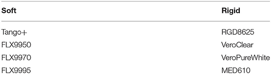
Table 1. List of studied materials and classification in soft and rigid ones.
Effects on the mechanical properties were examined for three different build orientations (XY, YX, ZX). A schematic illustration of the resulting anisotropy caused by the unique build procedure is given in Figure 1. Subsequent layers are indicated by an alternating orange-and-white shading, whereas, intersections within the layers, resulting from material deposition of adjacent nozzles, are indicated as cylinders (not in scale) [3]. Conducted experiments are based on a classical one factor at a time approach, whereby, factors of interest are investigated one after another. As only one factor is changed per run, this experimental approach does not provide information on interaction effects between the factors [3, 21]. For each material and orientation, six specimens of type 1A were manufactured and tested (in total 144 specimens). In this case, one factor (orientation) is investigated at three different levels (XY, YX, ZX). In addition, determined tensile moduli were compared with tensile moduli found in soft biological tissues.
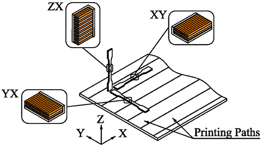
Figure 1. Studied build orientations of the tensile test specimens for investigating the mechanical and dimensional properties, depending on the orientation. Subsequent layers are indicated by an alternating orange-and-white shading, whereas, intersections within the layers, resulting from material deposition of adjacent nozzles, are indicated as cylinders (not in scale).
Specimen Manufacturing (Printing Operations)
All type 1A tensile specimens were printed on an Objet 500-Connex3 3D printer in Digital Material Mode with matte surface finish. This printing mode was selected, as it is the only printing mode that allows mixing of materials. In contrast to glossy surface finish, matte surface finish provides a very similar surface quality for all side surfaces of the printed parts. In addition, matte surface finish allows printing of sharp edges, as the parts are completely covered in support material, which prevents the deposited uncured layers from running [6]. Alignment of the specimens (six specimens per material and printing orientation) on the build platform was not done using the automatic printer setting but manually as shown in Figure 2. Materials were assigned randomly within the tray to reduce influences of possible location effects [7]. Flat (XY and YX) and vertical (ZX) oriented specimens were printed separately in order to avoid UV overcuring effects, which could be caused by different heights of parts located on adjacent printing paths [7]. To reduce wobbling of ZX-oriented specimens during the build procedure [5], those specimens were printed within an additional support construction. The design of this support construction consists of a wall, enclosing the support material in which the specimens are printed. An illustration of the specimen alignment on the trays is given in Figure 2.
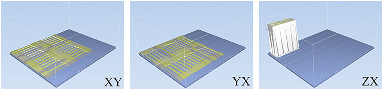
Figure 2. Schematic illustrations (generated in Objet Studio software) of the printing trays. Various colors of the tensile specimens indicate different materials. ZX-oriented specimens are enclosed in an additional support construction (in white color).
Postprocessing and Conditioning of the Specimens
Support removal was performed in a custom-made water jet cabin. To remove fine residues of support material, specimens were additionally soaked in a freshly prepared 3% NaOH solution (sodium hydroxide, pearl, 97%; Thermo Fisher Kandel GmbH, Kandel, Germany) for a duration of 15 min. Specimens were then rinsed under running water. To avoid long-term water contact, specimens were immediately dried after support removal by means of a cloth. Support removal of the specimens made from the medical-grade material MED610 was carried out following the guidance “Bio-Compatibility Requirements” [22], provided by the material supplier.
After support removal, specimens were conditioned for 88 h at a standard atmosphere class 2 (23 ± 2°C and 50 ± 10% r.h.) [18]. Climatic conditions were recorded and checked in 15-min intervals, using an ISO-calibrated temperature logger (LOG220, Dostmann electronic GmbH, Wertheim-Reicholzheim, Germany). For better moisture balance, specimens were turned every 24 h.
Test Equipment
All tensile tests were performed on a uniaxial universal test machine (Beta 10-2,5; Messphysik Materials Testing GmbH, Fürstenfeld, Austria). The used test machine fulfills all requirements listed in DIN EN ISO 527-1/2 and the referred standard ISO 7500-1 [18]. An illustration of the used setup is shown in Figure 3. Because of large differences in expected mechanical properties of the materials under investigation, a large force range had to be covered during tensile testing. Demands on the measurement certainty of the transducers are particularly high if measurements of the tensile modulus are required [18]. To fulfill the high demands for recording of the test force, three load cells with different force ranges were used. For recording the change in length of the gauge section of the tensile specimens, a video extensometer system (ME-46; Messphysik Materials Testing GmbH) is used. This system basically consists of a video camera (OS-65D CCIR; Mintron Enterprise Co. Ltd., New Taipei, Taiwan) and an image processing software (Videoextensometer NG version 5.14.4; Messphysik Materials Testing GmbH) that captures the change in distance of two targeting labels (Z46-34; Zwick GmbH & Co. KG, Ulm, Germany), positioned on the specimens [23].
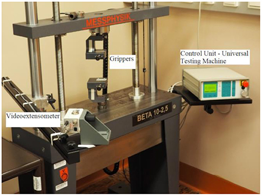
Figure 3. Tensile test machine including a video extensometer system.
Tensile Testing Procedure
For testing specimens printed from rigid materials, a 5-kN force transducer (TC4/5kN; AEP transducers, Cognento, Italy) was used. The preload value was set to 25 N and is within the limits defined in DIN EN ISO 527-1. As specified for this specimen type, the initial clamping distance is set to 115 mm. The distance of the video extensometer camera was adjusted to obtain a field of view of ~100 mm. Measurements of the tensile modulus are performed at a testing speed of 1 mm/min within the specified strain interval of 0.05–0.25%. The regression method was used to determine the tensile modulus. After a strain value of 0.3% is reached, the testing speed was switched to 20 mm/min, which corresponds to a nominal strain rate of 17.4% min−1. This testing speed was selected among specified values, listed in the standard. In regard to the high viscosity of the materials under investigation, the testing speed was chosen as slow as possible, but still allowing testing of all soft and rigid materials within a reasonable time. Because of the high ductility of the soft materials, different force transducers were required. Determination of the tensile modulus was carried out using a 20-N force transducer (S2/20N; Hottinger Baldwin Messtechnik GmbH, Darmstadt, Germany). After determination of the tensile modulus, a 1-kN load cell (TS C2 1kN, AEP transducers) was used to measure the tensile strength and elongation at break.
Dimensional Investigation of AM Parts
Experimental Design—Impact of Manufacturing Orientation Effects on Dimensional Accuracy
Stratasys Ltd. specifies the printing accuracy of the Objet500–Connex3 printer with 85 μm for parts with dimensions smaller than 50 mm and with 200 μm for dimensions >50 mm. These tolerances are provided only for rigid materials, whereas, no information is given about the tolerances for soft materials such as, for Tango+ [24]. As part of the tensile tests, it is necessary to determine the cross-sectional area of the tensile specimens. These data are calculated from the mean width and thickness, determined within the gauge section of the specimens [18]. The obtained dimensional data were further used to evaluate the dimensional accuracy in dependency of the build orientation (XY, YX, ZX) of the specimens. Studied dimensions are the width (b1) and height (h) within the gauge section, as well as the overall length (l3) of the specimens. Locations of the measurement points are given in Figure 4 (five measurement points for b1 and h, one measurement point for l3).
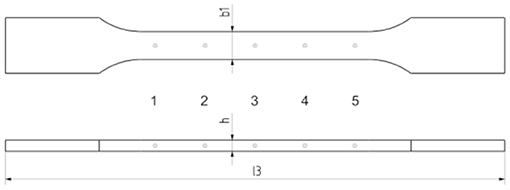
Figure 4. Measuring points located on the type 1A tensile specimen.
Used Measuring Equipment
DIN EN ISO 527-1 stipulates that dimensions of tensile test specimens, made from rigid plastic materials (Et >700 MPa), must be determined in accordance with DIN EN ISO 16012. Following this standard, the thickness (h) and width (b1) of the test specimens, printed from rigid materials, were determined by means of a digital micrometer (MDC-25PX; Mitutoyo Corp., Kawasaki, Japan). The length (l3) of the specimens was determined using a digital Vernier caliper (CD-S20CK; Mitutoyo Corp.). For the specimens made from soft materials, the width (b1) was determined by means of a projection microscope (PJ-3000; Mitutoyo Corp.). Measurements of the thickness (h) were conducted by means of a thickness gauge (NO.7301; Mitutoyo Corp.) in accordance with approach A of DIN ISO 23529 [25]. The length (l3) of the soft specimens was determined with the same procedure as for the rigid materials (Vernier caliper).
Data Evaluation and Statistical Methods
Data evaluation and statistical analysis were done in MATLAB R2017b (The MathWorks Inc., Natick, MA, USA). For statistical testing of orientation-dependent differences in the mechanical properties and in the dimensional accuracy, a one-way analysis of variance (ANOVA) was performed. Adequacy of the measurement data was checked by normal probability plots and by Shapiro–Wilk tests for normality (standard 5% significance level). The decision for this test is based on the highest statistical power compared to other tests for normality (Kolmogorov–Smirnov, Anderson–Darling) [26]. In case of a rejected null hypothesis (there is a statistically significant difference between the groups), the one-way ANOVA does not provide information about which groups have statistically different means. To obtain this information, a Bonferroni post-hoc test was carried out. In comparison to the most commonly used and more powerful Tukey post-hoc test, this test does not require equal sample sizes among the comparison groups and is therefore applicable, even if not all tensile tests provide valid results (e.g., in case one of the samples fractures in the neck region) [21].
Results
Impact of Manufacturing Orientation on Mechanical Properties
Mean tensile properties and corresponding standard deviations (SDs) of the tested material types are given in Table 2. A graphical illustration (boxplots) of the obtained mechanical data is given in Figure 5. Sample comparisons of the obtained stress-strain curves of the soft materials are shown in Figure 6. For the material mixtures (FLX9950, FLX9970, FLX9995, and RGD8625), it can be seen that the tensile modulus and the tensile strength increase for materials, containing higher percentage of VeroClear, whereas, the strain at break follows an opposite trend.
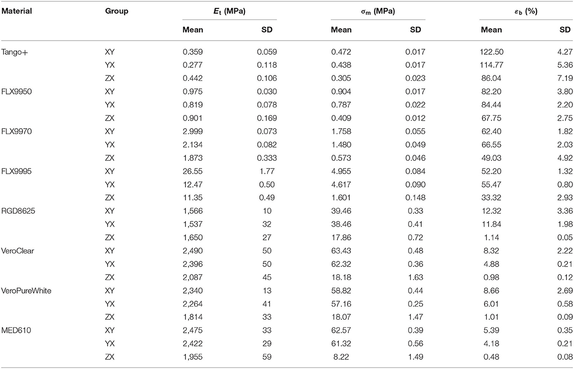
Table 2. Mean mechanical data (n = 6 for each mechanical property and each group) and corresponding standard deviations (Et, tensile modulus; σm, tensile strength; εb, elongation at break).
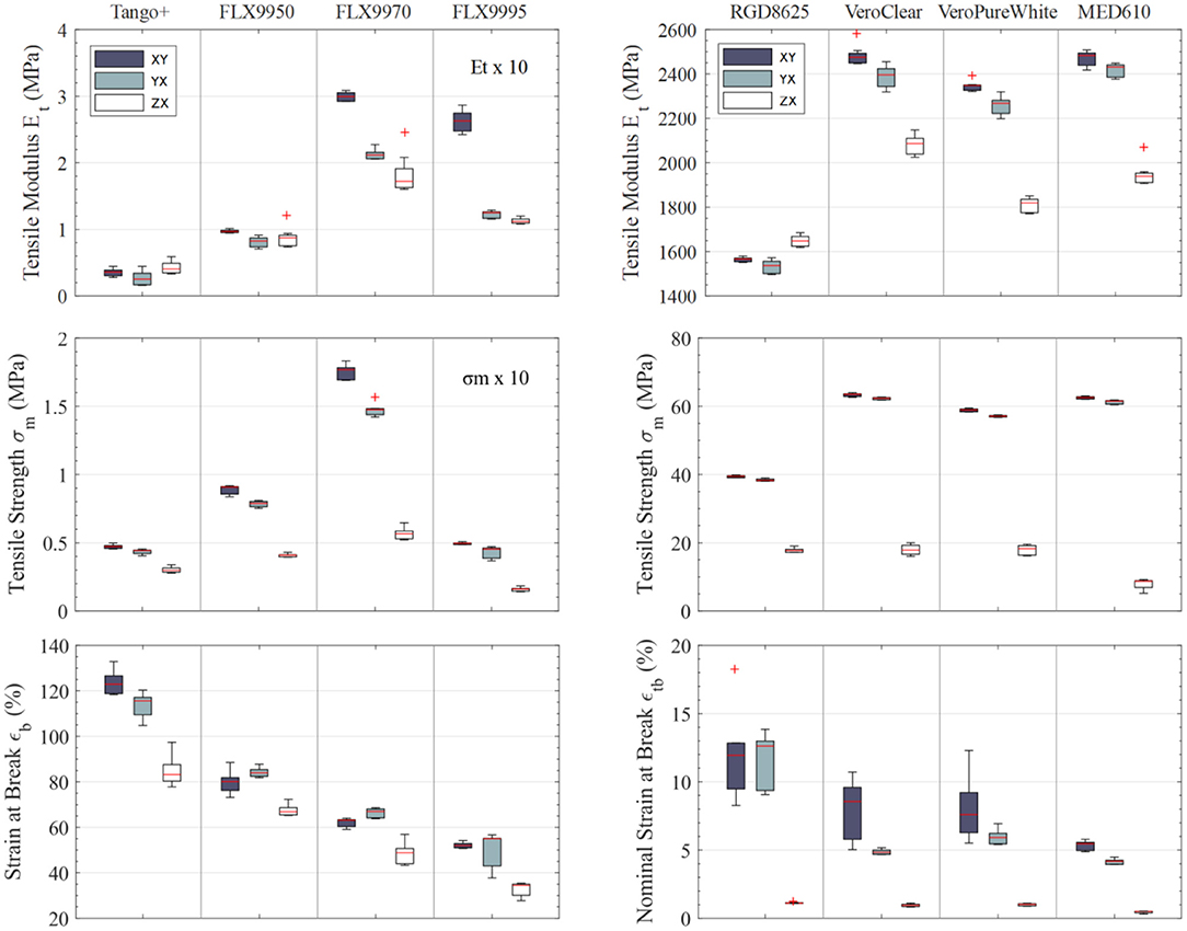
Figure 5. Boxplots of the mechanical data of all tested materials at different orientation levels (n = 6 for each of the three orientation levels and for each material). Red bars within the interquartile range delimited by the box itself show the median value; outliers are shown as red + signs.
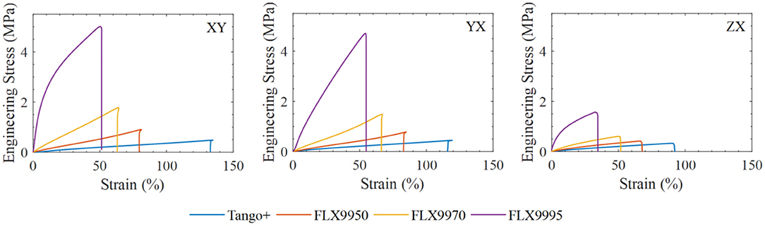
Figure 6. Soft materials. Sample comparison of the stress-strain curves of the different materials and orientation considered.
Results of the performed one-way ANOVA show statistically significant differences for all materials, except for the tensile modulus of FLX9950. Obtained p-values of the conducted multiple comparison tests with Bonferroni correction are given in Table 3. p-values, showing significant differences between the compared groups, are highlighted in bold.
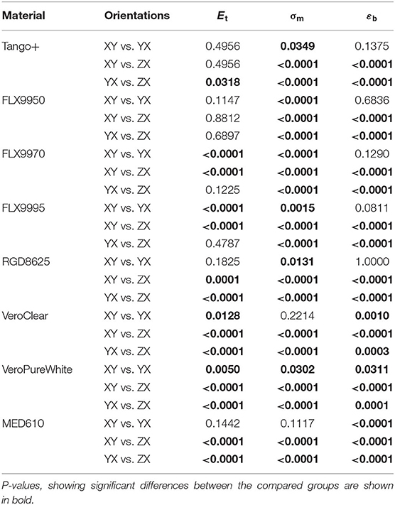
Table 3. p-Values of the multiple comparison tests with Bonferroni correction (Et, tensile modulus; σm, tensile strength; εb, elongation at break).
All mechanical measurement data and test protocols are available upon request.
Impact of Manufacturing Orientation on Dimensional Accuracy
Mean dimensional data and corresponding SD, determined on the tensile test specimens, can be taken from Table 4. Data of h and b1 represent the arithmetic mean of 30 measurements (five measurements on each of the six specimens), whereas, the arithmetic mean of l3 was calculated from six measurements (one measurement on each of the six specimens). Results show statistically significant differences between orientation levels for every rigid material. Obtained p-values of the multiple comparison tests are given in Table 5. p-Values, showing significant differences between the compared groups, are shown in bold font. No statistically significant differences could be found for the length between groups XY and ZX and for the thickness between XY- and YX-oriented specimens, manufactured from RGD8625. In addition, no statistically significant difference was found for the length l3 between the groups XY and YX of the materials MED610 and VeroPureWhite. All other obtained p-values show statistical difference between the compared groups. An illustration (boxplots) of the obtained dimensional data is given in Figure 7. Sample comparisons of the obtained stress-strain curves of the rigid materials are shown in Figure 8. Nominal dimensional data are depicted with a red dashed line. In general, it could be observed that ZX-oriented specimens, made from rigid materials, were printed slightly larger than flat-positioned specimens. In contrast to that, ZX-oriented specimens made from material mixtures show increasing shrinkage when containing higher percentages of Tango+. A visualization of the increasing dimensional deviation of ZX-oriented specimens made from material mixtures is given in Figure 9.
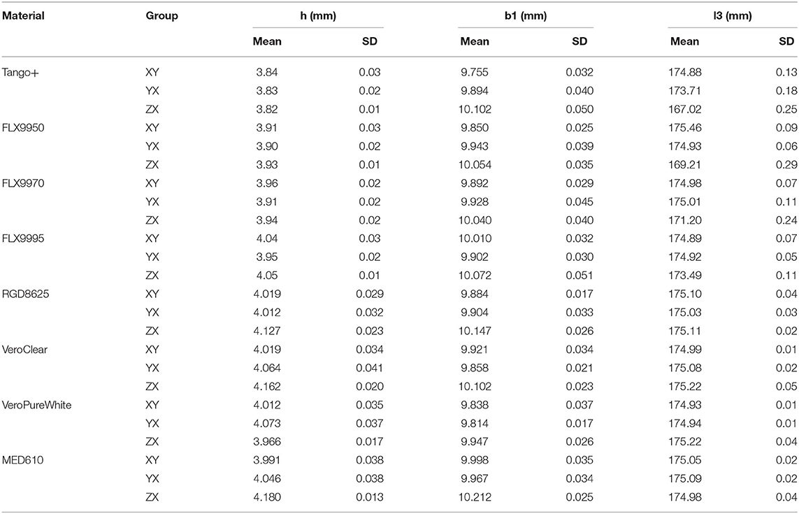
Table 4. Mean dimensional data (n = 30 for h and b1, n = 6 for l3) and corresponding standard deviations (SD) (h, thickness; b1, width; l3, length of the type 1A tensile specimen).
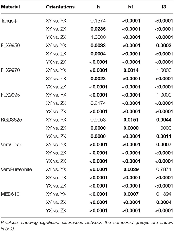
Table 5. p-Values of the multiple comparison tests with Bonferroni correction (h, thickness; b1, width; l3, length of the type 1A tensile specimen).
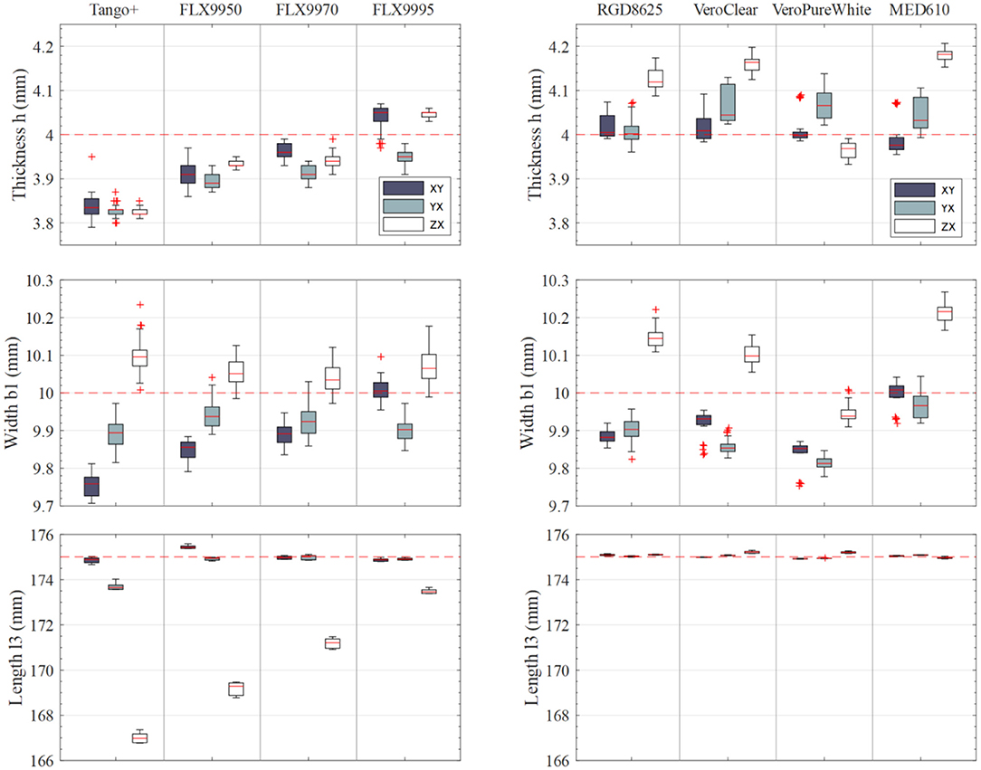
Figure 7. Boxplots of the dimensional data of all tested materials at three different orientation levels (n = 30 for h and b1, n = 6 for l3). Red dashed lines illustrate the nominal dimensional values. Red bars within the interquartile range delimited by the box itself show the median; outliers are shown as red + signs.
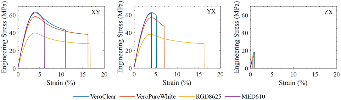
Figure 8. Rigid materials. Sample comparison of the stress-strain curves of the different materials and orientation considered.
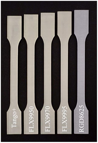
Figure 9. Illustration of the material shrinkage of ZX-oriented tensile specimens, manufactured from different digital materials (combination of Tango+ and VeroClear). The rigid material RGD8625 shows the lowest deviation (+0.11 mm on average) from the nominal length (l3 = 175 mm).
All dimensional measurement data and test protocols are available upon request.
Discussion
Impact of Manufacturing Orientation on Mechanical Properties
Results of the tensile tests have shown the lowest tensile strength for ZX-oriented specimens, followed by YX and XY orientations. While only small differences in strength were found between XY and YX orientations, significantly lower values were determined on ZX-oriented specimens. For rigid materials, ZX-oriented specimens have shown a tensile strength of only 13–45% compared to the strength of XY-oriented specimens. Lower differences in tensile strength were found for the soft materials, whereby, ZX-oriented parts have shown 32–65% of the tensile strength of XY orientations.
Highest variations in the determined tensile moduli could be observed for the softer materials (as shown by the SDs in Table 2). This could be based on variations in the measurement setup. Providing adequate clamping conditions of soft specimens turned out to be difficult. It could be observed that applying too high clamping forces lead to deformation of the specimen shoulders, resulting in an initial bending of the specimens within the gauge length. This bending of the specimens is corrected by applying a preload prior to testing. Calculation of the maximum allowed preload force is based on the expected tensile modulus of the material under investigation. For very soft materials such as Tango+, this preload force is in the range of the weight force of the specimens itself. This, in fact, means that testing could probably have started slightly before the specimens were correctly aligned (slightly bended gauge length), which may have an impact on the variation of the determined tensile moduli. We indeed preferred to start the measurement once the (low) preload was reached as demanded by the DIN EN ISO 527-2 standard. The higher variation in the strain at break for more rigid materials may be due to be a brittle characteristic of the material itself.
In general, rigid pure materials (VeroClear, VeroPureWhite, MED610) follow the same trends, whereby, the tensile modulus, tensile strength, and the nominal strain at break are the highest for XY- oriented specimens, followed by YX and ZX orientations. Highest effects on the mechanical properties were found for ZX-oriented specimens, whereby, the highest difference in tensile strength between orientations was found for MED610. ZX-oriented specimens of this material provide only 13% of the tensile strength of XY-oriented specimens. This could be attributed to the much longer time of chemical loading during the support removal procedure, which was carried out in accordance with the guidance for biocompatibility requirements, provided by the supplier (Stratasys Ltd.). Because of the much higher surface roughness of ZX-oriented specimens, these specimens show a much larger surface area and thus might facilitate impregnation of chemical compounds such as NaOH and isopropanol into the material. Differences in tensile strength between flat-positioned specimens and ZX-oriented specimens, made from soft materials, decrease for material mixtures containing a higher percentage of Tango+ (Figure 5). All tested materials follow the same trend for variation in tensile strength, whereby, XY-oriented specimens have shown the largest tensile strength, followed by YX- and ZX-oriented specimens. All differences in tensile strength were found to be statistically significant. Similar trends can also be observed for the strain at break of FLX9950, FLX9970, and FLX9995, whereby, YX-oriented parts have shown the highest values. Tango+ deviates from this trend and exhibits the highest strain at break for XY- oriented parts, followed by YX and ZX orientations.
In comparison to the flat-positioned specimens, the build procedure of ZX-oriented specimens takes much longer, leading to a higher UV exposure than for flat-positioned parts. In general, higher UV exposure is assumed to result in higher mechanical strength of the parts. Nevertheless, overcuring of the parts could also lead to a more brittle material behavior as seen in rigid ZX-oriented specimens [3]. Based on the layer-wise build procedure, ZX-oriented parts are characterized by a much higher number of interlayer bonds, a schematic illustration is given in Figure 1 [3]. The much higher number of layers increases the possibility in process-related defects in the specimens. Such defects could be, for example, weak interlayer bonds, caused by inclusions of residuals of support material between the layers. As ZX-oriented specimens fractured by delamination of the layers, interlayer bonds are assumed to be the source of weakening of those parts. The differences in mechanical properties between XY- and YX-oriented specimens can be described by means of weakening effects attributed to material intersections within the layers (Figure 1). A comparison of the determined tensile moduli with tensile moduli of different soft biological tissues found in literature [27] (Table 6) shows that biological tissues provide similar tensile moduli as the investigated soft materials. Depending on the build orientation, the material FLX9995 would allow simulation of skin, liver, and kidney tissue, whereas, the other material mixtures show tensile moduli similar with those of arteries, veins, cornea, sclera, spinal cord, and gray matter.
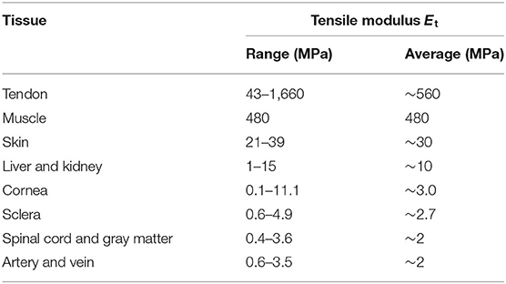
Table 6. Tensile modulus of soft tissues found in literature, reproduced from McKee et al. [27].
Determined mechanical values of the investigated materials can be used for simple computational strength calculations. Consideration of anisotropic effects allows correct dimensioning of parts that are mechanically loaded. This is essential for the design of medical devices such as for cutting guides or patient-specific surgical instruments. Especially keeping the mechanical weakness of Z-oriented structures in mind will help to avoid wrong part dimensioning and failure.
Impact of Manufacturing Orientation on Dimensional Accuracy
Results of the dimensional measurements carried out on the rigid tensile test specimens have shown higher dimensional deviations than specified by the manufacturer (Stratasys Ltd.). Without regard to the build orientation, observed deviations from the nominal dimensions are in the range between −0.2 and +0.2 mm for rigid materials. The observed greater width and thickness of ZX-oriented specimens could be attributed to wobbling of the parts during the build procedure, resulting in a larger width and thickness of the specimens. Although, ZX- aligned parts were printed within a support structure to avoid such movements during printing, this assumption is strengthened by the fact, that those specimens have shown slightly larger dimensions at their upper ends. In general, it can be stated that XY-oriented specimens show the lowest deviations from the nominal thickness and from the nominal width, followed by YX orientations. The higher accuracy in width of XY-oriented specimens could be attributed to the fact that the deposition process of the model and support material takes place simultaneously for dimensions aligned in parallel to the Y-axis of the printer. Not all specimens fulfill the dimensional tolerances (specimens made from MED610), stipulated in DIN EN ISO 527-2. The tolerance of the height h is specified with 4 ± 0.2 mm, whereas, the width b1 is specified with 10 ± 0.2 mm.
Specimens made from soft materials have shown other trends for their dimensional accuracy, compared to that of specimens made from rigid materials (Figure 7). It can be seen that specimens manufactured from softer materials show in general a smaller thickness than harder materials. The same trend was found for the width of XY-oriented specimens and for the length, determined on ZX orientations. Highest deviations in the length of the specimens were found for ZX-oriented specimens. Because of the large nominal dimension of the length (175 mm), shrinkage of ZX-oriented specimens could be already observed during visual inspection. Prior to support removal, it could be observed that all specimens had the same length (upper surfaces of the specimens and bottom surfaces of the specimens were all at the same level). Shrinkage became apparent immediately after support removal.
As the specimens were printed all together (rigid and soft specimens) within a support structure (Figure 2), mechanical compression of the roller can be excluded to be the reason for the length deviation in ZX-oriented specimens. Another aspect that excludes mechanical compression to be the reason for the length deviation of ZX-aligned specimens is the fact that rigid specimens, as well as the support structure that were simultaneously printed with the soft specimens, do not allow deformation by the roller to this extent.
For investigating the isotropic behavior of the material shrinkage, it would be most valuable to compare the shrinkage in length, as well as of the other dimensions (width and thickness) of the XY-, YX-, and ZX-aligned specimens. When comparing the length, it could be observed that shrinkage was mainly an issue in the ZX-oriented soft specimens. A reason for the larger shrinkage in the ZX direction could be due to the higher UV exposure in ZX printing orientation. This is mainly due to the fact that a print layer has a height of 32 μm. This results in a number of 125 layers for the flat-positioned specimens, whereas, more than 5,000 layers were required for the specimens produced in the ZX direction. A longer UV exposure time, as it occurred in the ZX direction, or after a postcuring treatment, typically leads to some shrinkage. We therefore think that this longer UV exposure could be the reason for the greater shrinkage in the ZX orientation; however, further investigation would be necessary to thoroughly understand this phenomenon.
A visual comparison of ZX-oriented specimens is given in Figure 9. A higher shrinkage could be noticed for material mixtures with higher concentrations of Tango+. Highest deviations in length were determined on ZX-oriented specimens, made from Tango+. These specimens have shown an 8-mm smaller length than specified in the STL file (175 mm).
Similar trends of orientation effects could be observed for the width of the materials Tango+, FLX9950, and FLX9970. For those specimens, the width was found to be the smallest for XY orientations, followed by YX and ZX orientations. These materials have shown the lowest deviation in width for ZX- and YX-oriented specimens. Without regard to the orientation level, deviations in width and in the thickness are in the range of −0.2 to +0.2 mm for the soft materials.
In general, it could be observed that specimens made from material mixtures, containing a higher percentage of Tango+, show a smaller thickness. Although statistically significant differences between most orientation levels were found for the thickness, no similar trends could be observed for the different material mixtures. Trends between the different orientation levels could be observed for the width of the specimens, whereby, the width was observed to be the smallest for XY-oriented specimens, followed by YX and ZX orientations. As for the rigid materials, it could be assumed that the width of the ZX-oriented specimens was printed larger due to wobbling during the build procedure.
As for the rigid material types, the differences between the mean widths of XY- and YX-oriented specimens could be attributed to the different material deposition process, whereby, the printing resolution in Y direction is limited by discretized nozzle positions of the printheads. This leads to systematic deviations in dimensions aligned along the Y-axis of the printer (width of XY aligned specimens and length of YX aligned specimens). Although, the specimens were printed on different tray positions, these systematic deviations did not reflect in the obtained data, as normal probability plots have shown that dimensions, which should be affected by discretized nozzle positions (width of XY specimens and length of YX specimens), are normally distributed. This suggests that the used measurement setup is not capable of showing this influencing factor.
Gained knowledge of orientation-dependent dimensional printing accuracy helps to ensure keeping necessary tolerances for manufacturing of anatomical models. This is especially relevant if those models are aimed to be used for correct sizing of implants, such as for selection of prosthetic heart valves or fitting surgical plates on anatomical bone structures. As shown in this article, keeping orientation-dependent accuracies in mind gets even more important if soft materials are used for printing. It seems that shrinkage of Z-oriented structures, printed from soft materials, is linear and allows simple correction by scaling the height of the model by applying a constant scaling factor.
Limitations and Outlook
Within this study, materials were only tested for their pure elastic behavior. During testing, it could be clearly observed that the materials show high viscosity. An investigation of the viscoelastic properties seems relevant for the design of biomechanical models, especially for cardiovascular applications. Moreover, there are additional materials that need to be characterized if the mechanical properties of the tested materials do not fit for the desired application field. Besides dimensional characterization of the printer, also geometrical (e.g., roundness, parallelism, etc.,) accuracies need to be determined. A potential source of error for all conducted experiments are inconsistent time intervals between manufacturing of the specimens and the performed test [3, 7]. Nevertheless, these effects are assumed to have only a low influence on the mechanical properties within the time span the experiments were performed [5].
Conclusions
AM is still a very dynamic and innovative field, which gives rise to a lot of new possibilities in the medical sector. Current standards for AM part characterization are still in development, and up to now, only a few general standards exist. Besides the possibility of different part orientations in AM technologies, resulting in different mechanical characteristics, multimaterial printers, such as the investigated Objet500–Connex3 printer, pose additional challenges for process understanding and require a lot of effort for full machine-material characterization. Published studies on multimaterial part characterization are rare and show limitations based on non-standard compliant investigations. Within the conducted tensile tests, influences of different build orientations on the mechanical properties were investigated. Eight different materials were tested in three different build orientations. With a few exceptions, it turned out that XY-oriented specimens show the highest tensile modulus, followed by YX and ZX orientations. For the tensile strength, a similar trend was found. In general, the lowest strain at break was found for ZX-oriented specimens. For investigation of the influence of orientation effects, dimensional tests were performed on tensile test specimens. For ZX-oriented specimens made from soft materials, high shrinkage (up to 4.6% of the nominal value) was found in the length of the specimens. In general, it can be said that the width and thickness of flat-oriented specimens are printed with an accuracy of ±0.2 mm for all investigated materials.
Data Availability Statement
The original contributions generated for the study are included in the article/supplementary material, further inquiries can be directed to the corresponding author/s.
Author Contributions
MK was involved in literature research, study design, experimental work, data analysis, writing the manuscript, and submission process. MS, EU, and CG were involved in study design and 3D printing. FM was involved in funding acquisition, study design, data analysis, writing, and submission process. All authors contributed to the article and approved the submitted version.
Funding
This project was funded by the Austrian Research Promotion Agency (FFG), Project Additive Manufacturing for M3dical RESearch, M3dRES (Nr. 858060).
Conflict of Interest
The authors declare that the research was conducted in the absence of any commercial or financial relationships that could be construed as a potential conflict of interest.
References
2. Khorram Niaki M, Nonino F. The Management of Additive Manufacturing. Cham: Springer International Publishing (2018). doi: 10.1007/978-3-319-56309-1
3. Mueller J, Shea K, Daraio C. Mechanical properties of parts fabricated with inkjet 3D printing through efficient experimental design. Mater Des. (2015) 86:902–912. doi: 10.1016/j.matdes.2015.07.129
4. Chua CK, Wong CH, Yeong WY. Standards, Quality Control, and Measurement Sciences in 3D Printing and Additive Manufacturing. 1st ed. London: Academic Press (2017). doi: 10.1016/B978-0-12-813489-4.00001-5
5. Bass LB, Meisel MA, Williams CB. Exploring variability in material properties of multi-material jetting parts. In: Proceedings of the 26th Annual International Solid Freeform Fabrication (SFF) Symposium—An Additive Manufacturing Conference. Austin, Tx. (2015) p. 993–1006. Available online at: http://utw10945.utweb.utexas.edu/2015TOC
6. Kesy A, Kotliński J. Mechanical properties of parts produced by using polymer jetting technology. Arch Civil Mech Eng. (2010) 10:37–50. doi: 10.1016/S1644-9665(12)60135-6
7. Barclift MW, Williams CB. Examining variability in the mechanical properties of parts manufactured via polyjet direct 3D printing. In: International Solid Freeform Fabrication Symposium. Austin, TX (2012) p. 6–8. Available online at: http://utw10945.utweb.utexas.edu/2012TOC
8. Deutsches Institut für Normung. DIN EN ISO 17296-3:2016-12, Additive manufacturing – General principles – Part 3: main characteristics and corresponding test methods (ISO 17296-3:2014).
9. Slesarenko V, Rudykh S. Towards mechanical characterization of soft digital materials for multimaterial 3D-printing. Int J Eng Sci. (2018) 123:62–72. doi: 10.1016/j.ijengsci.2017.11.011
10. Kaweesa DV, Meisel NA. Quantifying fatigue property changes in material jetted parts due to functionally graded material interface design. Addit Manuf. (2018) 21:141–9. doi: 10.1016/j.addma.2018.03.011
11. George E, Liacouras P, Rybicki FJ, Mitsouras D. Measuring and establishing the accuracy and reproducibility of 3D printed medical models. Radiographics. (2017) 37:1424–50. doi: 10.1148/rg.2017160165
12. Deutsches Institut für Normung. DIN EN ISO/ASTM 52900-15 Additive manufacturing - General principles - Terminology.
13. Kalaskar DM. 3D Printing in Medicine (Woodhead Publishing Series in Biomaterials). 1st ed. Duxford: Woodhead Publishing (2017).
14. Bibb R, Eggbeer D, Paterson A. Medical Modelling: The Application of Advanced Design and Rapid Prototyping Techniques in Medicine. 2nd ed. Amsterdam: Elsevier S & T (2014).
15. Farooqi KM, Uppu SC, Nguyen K, Srivastava S, Ko HH, Choueiter N, Wollstein A, Parness IA, Narula J, Sanz J, et al. Application of virtual three-dimensional models for simultaneous visualization of intracardiac anatomic relationships in double outlet right ventricle. Pediatr Cardiol. (2016) 37:90–8. doi: 10.1007/s00246-015-1244-z
16. Deutsches Institut für Normung. DIN EN ISO 17296-2:2016-12, Additive manufacturing – General principles – Part 2: Overview of process categories and feedstock (ISO 17296-2:2015).
17. Lumpe TS, Mueller J, Shea K. Tensile properties of multi-material interfaces in 3D printed parts. Mater Des. (2019) 162:1–9. doi: 10.1016/j.matdes.2018.11.024
18. Deutsches Institut für Normung. DIN EN ISO 527-1:2012-06, Plastics – Determination of tensile properties – Part 1: General principles (ISO 527-1:2012).
19. Deutsches Institut für Normung. DIN EN ISO 527-2:2012-06, Plastics – Determination of tensile properties – Part 2: Test conditions for moulding and extrusion plastics (ISO 527-2:2012).
20. Stratasys Ltd. Digital Materials Datasheet. Eden Prairie, MN: Stratasys Ltd. (2017). Available online at: http://global72.stratasys.com/~/media/Main/Files/Material_Spec_Sheets/MSS_PJ_DigitalMaterials_Datasheet_0617.ashx (accessed January 25, 2018)
21. Filliben JJ, Heckert A, Croarkin C, Hembree B, Guthrie W, Filliben J, et al. NIST/SEMATECH e-Handbook of Statistical Methods. (2013). Available online at: https://www.itl.nist.gov/div898/handbook/ (accessed April 9, 2018).
22. Stratasys Ltd. Bio-compatibility Requirements - Printing Bio-compatible Parts on PolyJetTM 3D Printers with MED610TM. Eden Prairie, MN: Stratasys Ltd. (2016). Available online at: https://stratasysstorage01.file.core.windows.net/ssys-websites-files-prod/Public1/Materials/Polyjet/Bio-compatible/MED610%20Biocompatibility%20Requirements.pdf?sv=2017-04-17&sr=f&sig=3wMnOvlXMsFT%2F9rDGaaKQ00ntufYA%2FXbDcir29n1Hrg%3D&st=2021-04-25T02%3A37%3A24Z&se=2022-04-26T02%3A37%3A24Z&sp=rwl (accessed February 16, 2018).
23. Deutsches Institut für Normung. DIN EN ISO 9513:2013-05, Metallic materials – Calibration of extensometer systems used in uniaxial testing (ISO 9513:2012 + Cor. 1:2013).
24. Stratasys Ltd. Objet350 and Objet500 Connex3 System Specifications. Eden Prairie, MN: Stratasys Ltd. (2016).
25. Deutsches Institut für Normung. DIN ISO 23529:2012-10, Rubber – General procedures for preparing and conditioning test pieces for physical test methods (ISO 23529:2010).
26. Seier E. Comparison of Tests for Univariate Normality. Johnson City, TN: East Tennessee State University. (2002) p. 17.
Keywords: additive manufacturing, multi-material jetting, tensile testing, printing accuracy, ISO 527-2:2012
Citation: Königshofer M, Stoiber M, Unger E, Grasl C and Moscato F (2021) Mechanical and Dimensional Investigation of Additive Manufactured Multimaterial Parts. Front. Phys. 9:635736. doi: 10.3389/fphy.2021.635736
Received: 30 November 2020; Accepted: 25 February 2021;
Published: 29 April 2021.
Edited by:
Qiyin Fang, McMaster University, CanadaReviewed by:
Dalia Mahmoud, McMaster University, CanadaDavid Rosen, Georgia Institute of Technology, United States
Copyright © 2021 Königshofer, Stoiber, Unger, Grasl and Moscato. This is an open-access article distributed under the terms of the Creative Commons Attribution License (CC BY). The use, distribution or reproduction in other forums is permitted, provided the original author(s) and the copyright owner(s) are credited and that the original publication in this journal is cited, in accordance with accepted academic practice. No use, distribution or reproduction is permitted which does not comply with these terms.
*Correspondence: Markus Königshofer, bWFya3VzLmtvZW5pZ3Nob2ZlckBtZWR1bml3aWVuLmFjLmF0