 Shinichi Saito
- Center for Exploratory Research Laboratory, Research & Development Group, Hitachi, Ltd., Tokyo, Japan
A Poincaré sphere is a powerful prescription to describe a polarized state of coherent photons, oscillating along certain directions. The polarized state is described by a vector in the sphere, and various passive optical components, such as polarization plates and quartz rotators are able to rotate the vectorial state by changing the phase and the amplitude among two orthogonal basis states. The polarization is originated from spin of photons, and recently, significant attentions have been made for optical Orbital Angular Momentum (OAM) as another fundamental degree of freedom for photons. The beam shape of photons with OAM is a vortex with a topological charge at the core, and the state of vortexed photons can be described by a hyper-Poincaré sphere. Here, we propose a compact Poincaré rotator, which controls a vortexed state of photons in a silicon photonic platform, based on Finite-Difference Time-Domain (FDTD) simulations. A ring-shaped gear is evanescently coupled to two silicon photonic waveguides, which convert optical momentum to OAM with both left and right vortexed states. By controlling the relative phase and the amplitude of two traveling waves in input ports, we can control the vortexed states in the hyper-Poincaré sphere for photons out of the gear. The impact of the geometrical Pancharatnam-Berry-Guoy's phase and the conservation law of spin and OAM for vortexed photons out of the gear are discussed.
1. Introduction
Planck discovered momentum p of a photon is determined by its wavelength λ in a vacuum as
where h is the Plank constant [1], ℏ = h/(2π)is the Dirac constant [2], and k is the wavenumber, through investigations on black body radiation [3, 4]. This discovery was a landmark for the development of quantum mechanics, which is based on fundamental principles of all elementary particles [5–7]. The quantization condition of the Plank formula was further refined by the Bohr-Sommerfeld model [3, 4, 8, 9],
where q is a generalized coordinate, which is the conjugate of the momentum p for a counter integration along a closed loop of C, and n is a quantum number for this orbital. By applying the quantization condition for the orbitals of electrons in an atom, the electronic structures were systematically classified by radial and azimuthal quantum numbers for energy and angular momentum to explain various material properties based on atomic orbitals for the periodic table [3, 4, 8, 9]. In modern quantum mechanics, momentum and angular momentum are understood based on generators of translational and rotational symmetries of the system [5–7, 10–13]. It is interesting to be aware that both photons and electrons are characterized by integer quantum numbers of orbitals, regardless of the difference in statistics governed by Bose-Einstein and Fermi-Dirac distribution functions, respectively [14–18].
Despite its historical importance on the nature of photons, it is relatively recent to pay attention to optical Orbital Angular Momentum (OAM) [19–46]. Allen et al. showed that the optical beam with Laguerre-Gauss mode carry OAM of ℏm per photon along the direction of propagation, where m is the integer quantum number to characterize the helical rotation of the phase front [19]. In order to allow the finite OAM (|m| ≠ 0), the amplitude of the Laguerre-Gauss mode must have nodes at the core, and m is the winding number of the phase along the closed contour perpendicular to the direction of propagation [19, 32, 33, 47–49]. m is also called as a topological charge [19, 21, 22, 26, 32, 33, 35, 38, 39]. From fundamental points of views, it was argued whether it is possible to split spin angular momentum and OAM from the total angular momentum defined from the Poynting vector [24], or not [20, 27, 34]. This issue is posing a critical question whether we can treat OAM as a similar degree of freedom with polarization [50, 51] for internal spin degree of freedom. It is beyond our scope of this paper to explore the splitting issue of spin and OAM in a rigorous way [20, 27, 34].
Practically, however, it is well-established that a state with OAM is described in a hyper-Poincaré sphere [21, 28, 36, 37] similar to a Poincaré sphere [52–54] for visualizing Stokes parameters [47, 48, 52, 54–64] of polarization states. Polarization states are described by two level systems corresponding to an arbitrary orthogonal states, such as left (|L〉) and right (|R〉) circularly polarized states, horizontally (|H〉) and vertically (|V〉) linear-polarized states, or diagonally (|D〉) and anti-diagonally (|A〉) polarized linear-polarized states [47, 48, 52, 54–64]. We can also consider corresponding states with OAM in the hyper-Poincaré sphere [21, 28, 36, 37]. We propose to call a beam with OAM as vortexed in a close similarity to polarized photons.
Padgett and Courtial proposed to use a hyper-Poincaré sphere by using a superposition states of left- and right- vortexed states, and demonstrated such a superposition state is controlled by a phase-shift, generated by rotated cylindrical lenses [21, 65]. In the definition of the work of Padgett and Courtial [21], the duality between vortexed states and polarized states was discussed in general, and the polarization state of the vortexed state was not specified. Thus, the superposition of left- and right vortexed states with a certain fixed polarization state was considered [21]. Later, Milione et al. clarified the polarization states for photons with OAM, and showed rich vortexed states could be realized by allowing the superposition states of orthogonally polarized states with a proper OAM [28]. Here, instead of considering left- and right-vortexed states, arbitrary polarized states with a certain vortexed state were clarified, and the further superposition states with different OAM states were also discussed [28]. More recently, several groups successfully generated arbitrary OAM states by transferring polarized states to vortexed states [36, 37, 66].
In order to change the polarized state in Poincaré sphere, we can utilize various passive and active optical components, such as retarder plates, phase-shifters, Mach-Zehnder modulators, quartz rotators and so on [48, 50, 51, 60, 62, 64]. We can also use several optical components, such as vortex retarders [25, 31] and novel micro-gears [29, 67–69] for the generations of beams with OAM.
In particular, the micro-gears [29, 68, 69] in a silicon (Si) photonic platform [70, 71] are promising to encode various vortexed states, such as amplitudes, phases, and vorticities (topological charges) for high-speed optical communications [72] as well as for potential quantum communications [46].
Nevertheless, it is not so straightforward to manipulate vortexed states dynamically for photons in the hyper-Poincaré sphere, compared with the polarized photons without OAM, due to the lack of appropriate phase-shifters and rotators for OAM, compared with those for polarization.
Motivated by these fundamental progresses on OAM and practical advances in Si photonics, here, we propose a Poincaré rotator to generate a beam with an arbitrary vortexed photons in an integrated optical circuit. We use Finite-Difference Time-Domain (FDTD) simulations for an Si micro-gear [29] evanescently coupled to two Si photonic wire waveguides (Figure 1). We discuss the impacts of the conservation law of OAM and spin as well as the geometrical Pancharatnam-Berry-Guoy's phase [26, 48, 73–76] for vortexed photons.
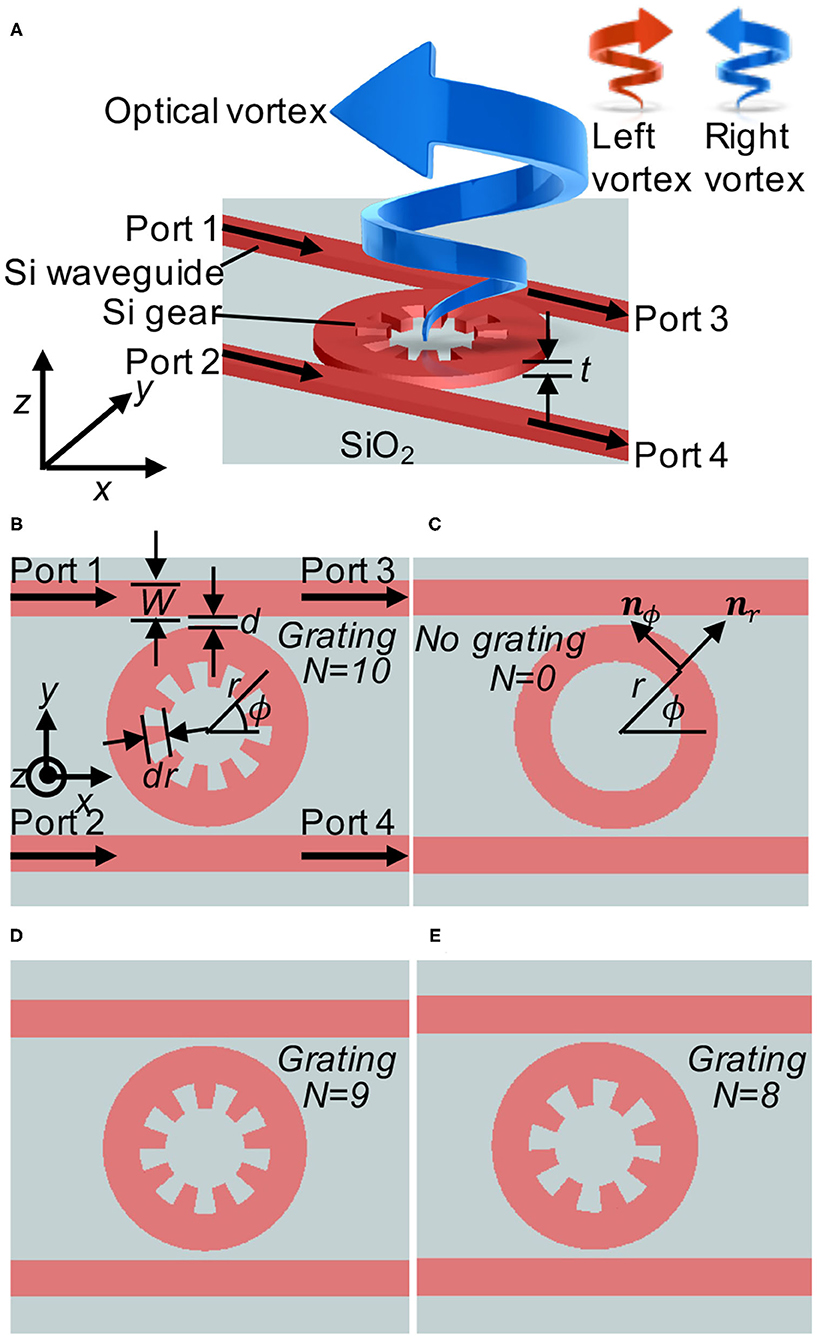
Figure 1. Poincaré rotator. (A) Birds' view of the proposed device. The silicon (Si) micro-gear is coupled to two Si wire waveguides located on top of silicon dioxide (SiO2). Two input ports (1 and 2) are used to inject photons with certain phases and amplitudes to generate a vortex beam with a superposition state of left and right vortexed states. The thickness of the Si layer is t = 220 nm. (B) Gear of the grating number N of 10. The width of waveguide is W = 440 nm. The depth of the grating dip is dr = 220 nm. The distance of between the gear and the waveguide is d = 100 nm. The radius of the grating is 1μm. (C) Ring resonator for the reference. Unit vectors of nr and nϕ are shown. (D) Gears of N = 9. (E) Gears of N = 8.
2. Model
2.1. Device Structure
The device structure is schematically shown in Figure 1. We assume the use of Si-On-Insulator (SOI) substrate with the top Si layer thickness t of 220 nm, on the buried-oxide (BOX) thickness of 2μm or beyond on top of the supporting Si substrate [70, 71]. Two standard straight wire waveguides are designed to be single mode with the width W of 440 nm. The polarization of the mode propagating in the Si wire waveguide is the quasi-Transverse-Electric (TE) mode [47, 48, 70], such that the electric field is dominated by the horizontal linearly polarized state with the momentum p = ℏkneff, given by the wavenumber kneff = 2πneff/λ with the effective refractive index of neff.
The Si wire waveguides are located near the Si micro-gear (Figures 1A,B,D,E) with the distance d of 100nm. We have also considered a ring resonator (Figure 1C) for the reference. The width of both gears and a ring is the same width (W) with the waveguide. The radius R of gears and a ring is 1μm.
For the gear, we introduced the grating in the inner surface of the ring. The depth of the dip dr = W/2 is designed to be half of the waveguide width. We have calculated modes for gears with the grating number N of 10 (Figure 1B), 9 (Figure 1D), and 8 (Figure 1E), respectively, in order to see the impact of the grating to the conservation law. The wavelength we have considered in this work is fixed at λ = 1, 540 nm, for which the grating of N = 10 satisfies the Bragg reflection condition.
Two input ports of 1 and 2 are used to inject photons from the waveguide into the gear. Photons from port 1 will couple to the gear to rotate along the right hand direction, seen from the top of the chip (from the +z direction), while photons from port 2 will rotate the gear along the left hand direction. The idea is to control the phase and the amplitude of the input ports to generate the vortexed photons under a superposition state between left and right vortexed states.
One might think that one bus arrangement is enough to generate both left- and right- vortexed states, as demonstrated in previous works [29, 68]. In our case, however, we are considering to connect the waveguides to integrated Si photonic optical modulators [70, 71, 77] to allow the phase-shift for left- and right-vortices. Unfortunately, the coupling efficiency to a ring resonator from a waveguide is not high [70, 78, 79], and it is extremely sensitive to temperatures. Therefore, we must avoid interferences from the lights passing into the other ports. So far, on-chip isolators [80] are not integrated as an option for standard foundries of Si photonics chip, yet. A practical option at this moment was to employ two-bus arrangements [69, 81], such that the transmitted lights in the through-ports could be terminated to avoid the back reflections.
Here, we had better to explain our definition of the rotation. We use a standard right handed (x, y, z) coordinate as shown in Figure 1. (x, y) define the plane for the surface of the SOI substrate, and z is perpendicular to the substrate. We define the direction of rotation of photons, seen from the detector side. We believe this is a natural direction to describe the rotation, since we consider the rotation of the phase front in the (x, y) plane for a vortex, propagating along the +z direction. Consequently, the phase front of the left vortex is rotating in the counter clock wise (left rotation), seen from the +z direction, while the phase front of the right vortex is rotating in the clock wise (right rotation). We had better to clarify the way to describe the time evolution of the wave. We use ei(kz−ωt) for the plane wave propagating along +z direction over t with the wavenumber of k and the angular frequency of ω. Physicists prefer this definition, while engineers prefer e−i(kz−ωt). Due to the duality for the definition of the imaginary number, i2 = (−i)2 = 1, both definitions work, properly. The use of a complex electric field is a useful technique to calculate an electro-magnetic field, and there is no issue to extract the observable real electric field by calculating the sum of the complex field and its complex conjugate at the end of the calculation [47, 48, 60]. But, the interpretation to consider the direction of the oscillation will be opposite in the complex fields of E, such that we needed to clarify to avoid unnecessary confusion. We are also aware that some physicists prefer to define the direction of rotation of photons, seen from the source side. This is in fact quite common, for example, to define the rotation of the screw driver or to consider the use of a handle to drive a car. However, as far as we use the left handed x = (x, y, z) coordinate, it is easier to show modes and phase angles in the (x, y) plane, such that the natural direction of the observation is from +z direction, which is the detector side. We needed to emphasize this point, since our results would be complicated, if we are not sure about our definition. We apologize from the beginning for those who are not happy about our convention.
We also use the cylindrical coordinate r = (r, ϕ, z), as shown in Figure 1C. The unit vectors along the radical and the azimuthal directions are nr and nϕ, respectively. These unit vectors depend on the locations, nr = nr(r, ϕ) = (cos ϕ, sin ϕ, 0) and nϕ = nϕ(r, ϕ) = (−sin ϕ, cos ϕ, 0), such that we must take care of the difference of the fixed unit vectors to define the (x, y, z) coordinate. Even if the components of (r, ϕ) are constant over the area, the real vectors in (x, y) coordinate are changing over the space.
2.2. Ring: Momentum to Orbital Angular Momentum Converter
First, we have simulated a standard ring resonator [70, 82] (Figure 1C) to understand how OAM is generated. The single mode in the waveguide has no orbital angular momentum, and it is propagating with the momentum of p = (px, 0, 0) injected from the input port 1 (Figure 2). If we do not have the gear, p is conserved due to the translational symmetry of the wire waveguide along the x direction. This symmetry is broken due to the presence of the ring, and the modes in the waveguide and the ring are degenerate at the point of contact, where the resonance to the ring waveguide is taking place [70, 82], and the fraction of photons are transferred from the waveguide to the ring resonator.
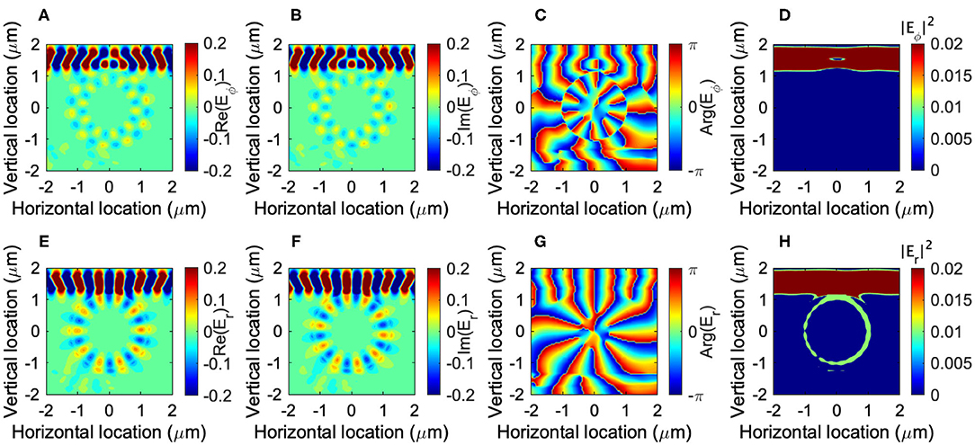
Figure 2. Ring resonator coupled to a wire waveguide. (A) Real and (B) imaginary part of the azimuthal component of the electric field, its (C) phase, and (D) intensity. (E) Real and (F) imaginary part of the radial component of the electric field, its (G) phase, and (H) intensity. The orbital angular momentum of m = −10 is obtained for a ring of the radius of 1μm at the wavelength of 1,540 nm. The mode is rotating along the clock-wise (right) direction.
The single mode of the input is oscillating predominantly along y direction, since it is a TE mode, given by E = (Ex, Ey) ≈ (0, Ey). We use the arbitrary units throughout this paper, and the input mode is normalized as
In order to see how the direction of oscillation has been changed, we have projected E = (Ex, Ey) to the azimuthal and the radical directions to get each component as
respectively. As shown in Figure 2, the mode in the ring resonator is predominantly oscillating in the radical direction (Figures 2E,F), such that the direction of the oscillation is perpendicular to the direction of the propagation. This is consistent with the single TE mode nature of the ring resonator. Nevertheless, some interesting features are already going on, since the unit vector nr is changing the direction along the circulation. Therefore, the polarization is changing azimuthally from horizontal, diagonal, vertical, vertical, back to horizontal upon the rotation. In other words, the average spin angular momentum becomes zero for the resonant mode, circulating in the ring resonator, because of the change in the direction of oscillation upon the time evolution. On the other hand, OAM becomes non-zero, since the mode acquired the phase as
where the m is the OAM component along the quantization axis of z. We confirm that it is the eignemode of the OAM operator
In our example of Figure 2, the input mode from the port 1 is coupled to the resonator mode of m = −10 and it is rotating along the clock-wise right direction, as is evident from the phase evolution from blue (the phase of −π), green, to red (the phase of π) toward the right circulation (Figures 2C,D). This corresponds to the right circulation over the time evolution. Due to the rotational symmetry of the ring, OAM is preserved, if it is isolated. In reality, the ring resonator is coupled to wire waveguides, such that the loss is expected to loose some fractions of photons leaking from the resonator. We also confirmed that Eϕ also has the same phase and OAM of m = −10.
In this classical example, we see that the momentum of photons in the waveguide is transferred to OAM in the ring resonator. Therefore, the ring resonator works as a converter of momentum to OAM. Due to the broken symmetry of the system, the momentum is not conserved, and it adiabatically changes the direction of the propagation. In the ring, it is circulating in the right direction, such that the mode acquired OAM.
It is also interesting to be aware that the Bohr-Sommerfeld quantization condition [3, 4, 8, 9],
is certainly satisfied to obtain the azimuthal component of the momentum
and the effective wavelength in the waveguide
It is also important to have a node at the center of the ring. In the ring waveguide, the amplitude of the mode vanishes at the center due to the absence of the material of a high refractive index, and therefore it is obvious. Even if we use a disk instead of the ring, the Whispering-Gallery-Mode (WGM) [67] has a node at the center. Otherwise, OAM would diverge at the center [19]. Thus, the finite m is also called as topological charge, since it characterizes the nature of the electric fields surrounding it. We had better to emphasize, though, that there is no physical observable in the unit of charge. There is no singularity of the fields, either. It is just a node, and m is the winding number of the phase to characterize the vortex, and m is the quantization integer for the OAM component along the direction of the propagation.
2.3. Gear: Generator of Vortices and Conservation Law for Optical Angular Momentum
Next, we discuss about the generation of vortices out of the gear, coupled to the Si wire waveguide [29, 68, 69]. Our design is much smaller than the original proposal of Cai et al. [29], and we found an interplay between spin and OAM upon the conservation law. In the design of Cai et al. [29], the depth of the grating is not significant, such that the small azimuthal component of Eϕ was scattered by the grating. On the other hand, the width of our grating is the half of the width of the waveguide, dr = W/2, (Figure 1B) and strong scattering of the entire mode is expected in our design.
First, we have simulated for the gear of N = 10 (Figure 1B). In this design, the Bragg reflection condition is satisfied, such that the grating will give the momentum of ℏ2π/Λ, where Λ = 2πR/N ~ 628nm is the period of the grating, and we expect
due to the momentum conservation law in a periodic system [48, 83–85]. Using the effective refractive index of the grating as the average value of Si and SiO2 as neff = (3.48 + 1.44)/2 = 2.46, we obtain λneff ~ 626 nm, and thus λneff ~ Λ. Therefore, the momentum of photons in the plane vanishes upon acquiring the Bragg momentum, and photons will be projected out of the gear.
The amplitudes and phases of the mode simulated at z = 1μm above the gear is shown in Figure 2. To our surprise, OAM was not zero, and both Ex and Ey showed the clear anti-clock-wise (left) circulation (Figures 3A–D) with the OAM quantum number of m′ = +1, where we used ′ to stand for the quantum number after the scattering. This corresponds to the left circulation of a vortex over the time evolution. We have numerically confirmed that OAM of the left-vortexed state (Figures 3B,D) is
which means that the winding number gives the expected z component of OAM.
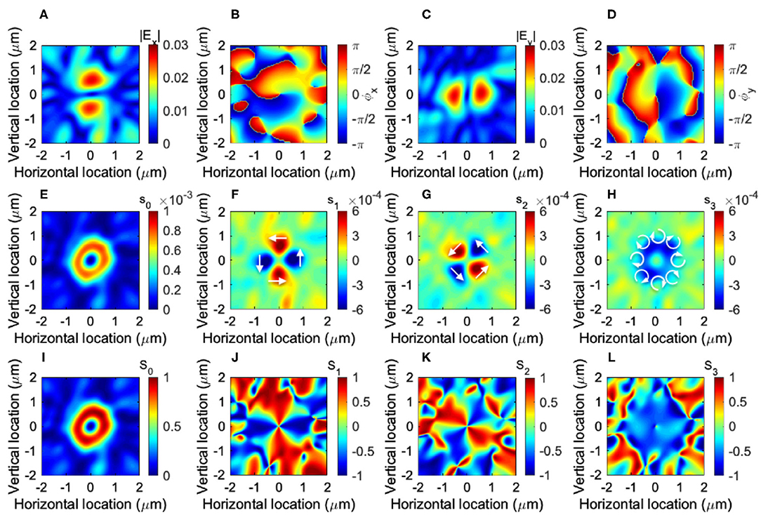
Figure 3. Left vortex generated from the gear of N = 10. The input port 1 is used to inject photons to the waveguide, and the mode profile is obtained at z = 1μm above the gear. (A) The amplitude (|Ex|) and (B) the phase (ϕx) of the horizontal electric field Ex. (C) The amplitude (|Ex|) and (D) the phase (ϕy)of the horizontal electric field Ey. They show , showing the direct tensor product state of the right-circularly-polarized state and the left-vortexed state, |↻〉spin⊗|↺〉orbit. (E) The local intensity, s0, (F) local horizontal/vertical spin component, s1, (G) local diagonal/anti-diagonal spin component, s2, and (H) local left/right spin component, s1. Normalized Stokes parameters of (I) S0, (J) S1, (K) S2, and (L) S3. White arrows in (F–H) schematically show the direction of oscillations.
The amplitudes of |Ex| and |Ey| show the presence of a node at the center of vortex. Moreover, if we compare the phase ϕx of Ex with the phase ϕy of Ey, it shows ϕy = ϕx − π/2, which means that spin s′ = −1, showing the right-circularly-polarized state. Consequently, our numerical simulation shows the left vortexed state, given by the extended Jones vector [48, 52, 55–57, 60]
where the first component is proportional to Ex and the second component is proportional to Ey. The polarization state is described by the SU(2) state [5–7, 10, 11]. Here, we have omitted to include the radial dependence, given by the Laguerre-Gauss function or the Hermite-Gauss function [19, 48]. The global phase factor of is not necessary but useful to understand the azimuthal component. The global phase also depends on the U(1) wave from e−i(kz−ωt), standing for the propagation along z and t, and the choice of the phase of is just coming from our random choice of the detector position at z = 1μm. The important point of our left-vortexed state |L〉 is based on the fact that it is a direct tensor product state of spin and OAM with opposite rotation. Therefore, it can also be described as
We described this state as left-vortexed state, since we are primarily interested in a vortex for the present work.
Consequently, the conservation law of angular momentum is described as
where s = 0, m = −10, N = 10, s′ = −1, and m′ = 1. Therefore, both spin and OAM are involved upon the scattering from our grating gear to produce a vortex, while the total angular momentum along the direction of propagation is zero due to the opposite rotation by spin.
The importance of the conservation law of spin and OAM of photons in a micro-gear was first discussed by Shao et al. [68], where the local spin components were experimentally measured and spin-orbit interaction was demonstrated. They used the gear with R = 80μm, and the conservation law of angular momentum at the local edge of the grating was discussed [68]. Our design is based on R = 1μm, and the entire mode profile affects the conservation law of angular momentum. Following the analysis [68], we have also calculated the local spin density of photons, s = (s1, s2, s3), defined by
which satisfy (Figure 3E). We have also calculated the local Stokes parameters, given by
which is normalized as at each point x, while S0 = S0(x) (Figure 3I) is a normalized s0 with its maximum value. As shown in Figures 3H,L, the local density of the right-circularly polarized state (s3 and S3) is distributed over the ring, which describes the opposite rotation of the polarization to the rotation of the left-vortex state, described by the left rotation of the phases (Figures 3B,D). We also found components of locally linearly-polarized states (s1 and s2), which are changing signs depending on the positions (Figures 3F,G,J,K) and described by
However, the overall contribution of this component to the total spin vanishes after the spatial integration, since both negative and positive values appeared equally (Figures 3F,G,J,K). Moreover, the contribution of this component to OAM also vanishes, which is confirmed by calculating
It is interesting to be aware that the local spin component is also circulating along the azimuthal direction (schematically shown as arrows in Figures 3F,G), due to the rotation of the phases (Figures 3B,D). Numerically, we have obtained the spatial averages of Stokes parameters, for the left-vortexed state. The spatial average of the OAM, , was 0.53. The reduction of the expected OAM of 1 from the left vortex is attributed to the contribution of the local spin component with vanishing OAM. This means that about 50% of the mode is made of the purely left-vortexed state under right polarization, while another 50% of the mode is made of the local spin components, which are characterized by spatially rotating linear polarization. Therefore, the efficiency to generate the left vortex out of our gear is about 50%.
In order to confirm our picture on the conservation law of angular momentum, we have also simulated for the gear of N = 9 (Figures 1D, 4). In this case, the node completely disappeared from the mode (Figures 2A,C), such that OAM cannot be sustained and we obtained m′ = 0 (Figure 4). On the other hand, we confirmed the same phase difference at the center of the mode as before ϕy = ϕx−π/2. Therefore, the state is simply described by a polarization state
which is the right-circulary-polarized state without a vortex. The nodeless mode profile was not reported in the previous work [29], such that our results are coming from the difference of the design of the gear. In our example, the conservation law for angular momentum is given by
where s = 0, m = −10, N = 9, s′ = −1, and m′ = 0. Therefore, the difference between N = 10 and N = 9 is exactly what we expected.
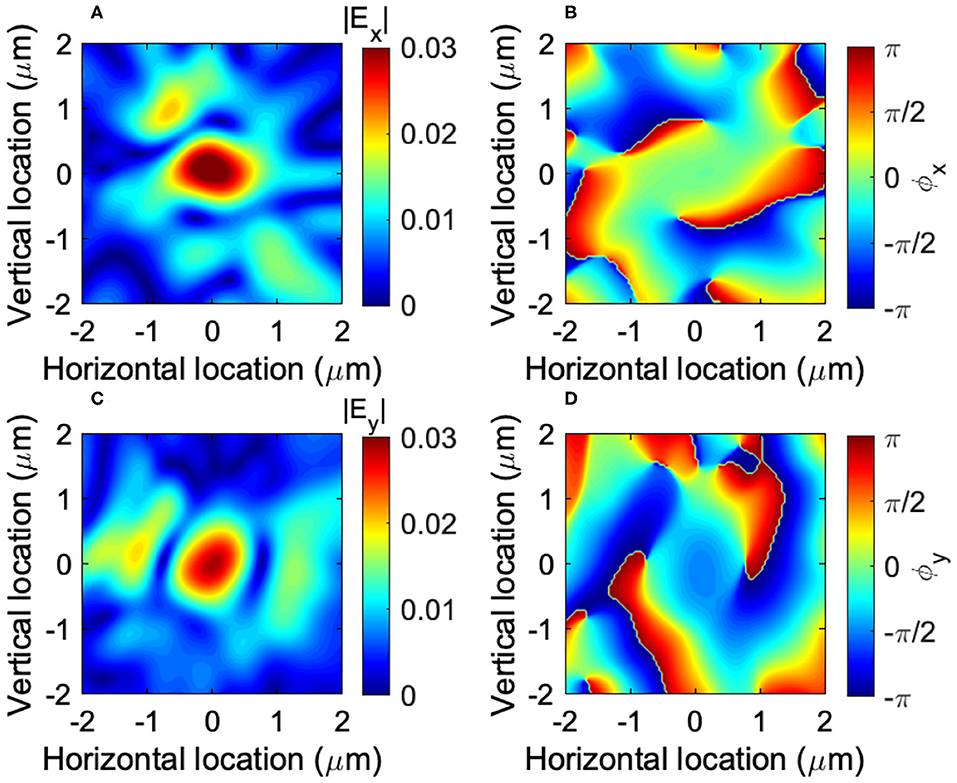
Figure 4. Right-circularly-polarized state, generated from the gear of N = 9. The input port 1 is used to inject photons to the waveguide, and the mode profile is obtained at z = 1μm above the gear. (A) The amplitude (|Ex|) and (B) the phase (ϕx) of the horizontal electric field Ex. (C) The amplitude (|Ex|) and (D) the phase (ϕy)of the horizontal electric field Ey. There is no node in the modes, such that there is no OAM. They show Ey ~ −iEx, such that the polarization is right-circularly-polarized state, |↻〉spin.
Furthermore, we have continued to simulate the structure of the gear with N = 8 (Figure 1E). In this case, the grating is far away from the perfect Bragg grating condition, such that the mode profiles are significantly distorted (Figures 5A,C). Nevertheless, they showed the presence of the node at the center (Figures 5A,C), and the phase is rotating along the clock-wise (right) direction (Figures 5B,D), which is completely opposite to the result for N = 10, as we expected from the conservation law. In this case, the vortexed state is described as
The conservation law for angular momentum is given by
where s = 0, m = −10, N = 8, s′ = −1, and m′ = −1.
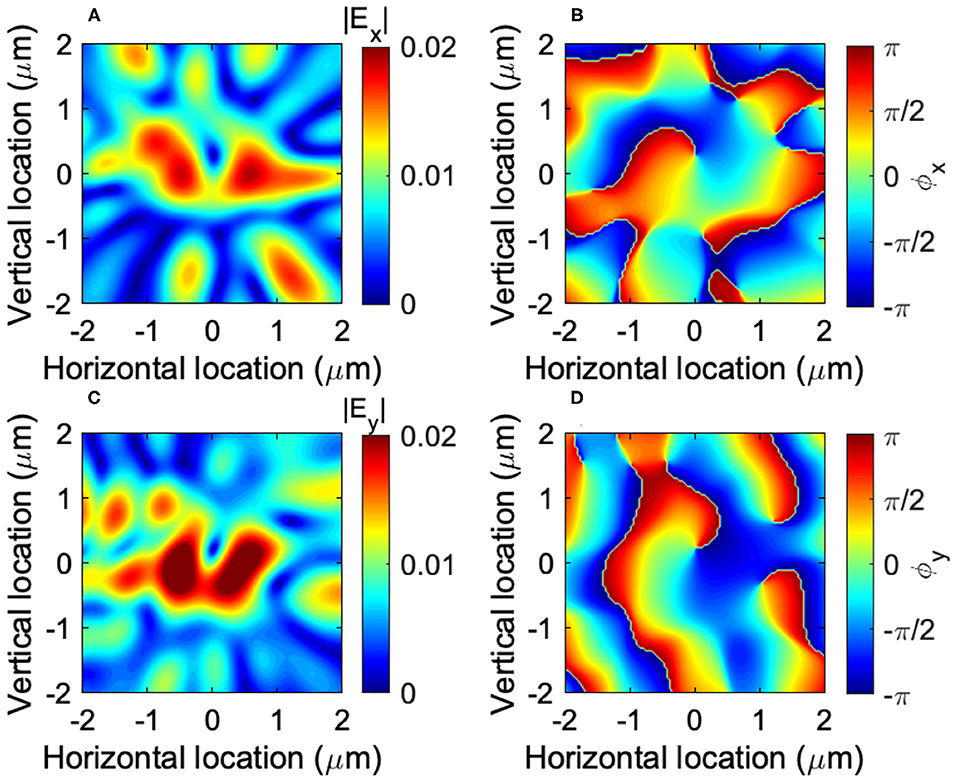
Figure 5. Right vortex generated from the gear of N = 8. The input port 1 is used to inject photons to the waveguide, and the mode profile is obtained at z = 1μm above the gear. (A) The amplitude (|Ex|) and (B) the phase (ϕx) of the horizontal electric field Ex. (C) The amplitude (|Ex|) and (D) the phase (ϕy)of the horizontal electric field Ey. They show , showing the direct tensor product state of the right-circularly-polarized state and the right-vortexed state, |↻〉spin⊗|↻〉orbit.
In all cases, the angular momentum is conserved upon scattering by gratings. It is important to consider both spin and OAM, simultaneously, to understand the conservation law. On the other hand, we cannot understand why s′ = −1 was always chosen for N = 10, 9, and 8, simply from the conservation law of angular momentum. This could be understood by the evolution of the phase front, as shown in Figure 6. The original input is TE polarized along y direction, such that the phase front of ϕy is going ahead of ϕx, and Ex acquires the same amplitude with that of Ey at the intersection only after the quarterly rotation (phases inside the ring of Figures 6B,C). As a result, we obtain ϕy = ϕx − π/2, if we compare the phases at the same position, leading to the generation of the vortex with right polarization (Figures 6N,P). Thus, the spin angular momentum is fixed, while OAM is determined by the conservation law of angular momentum.
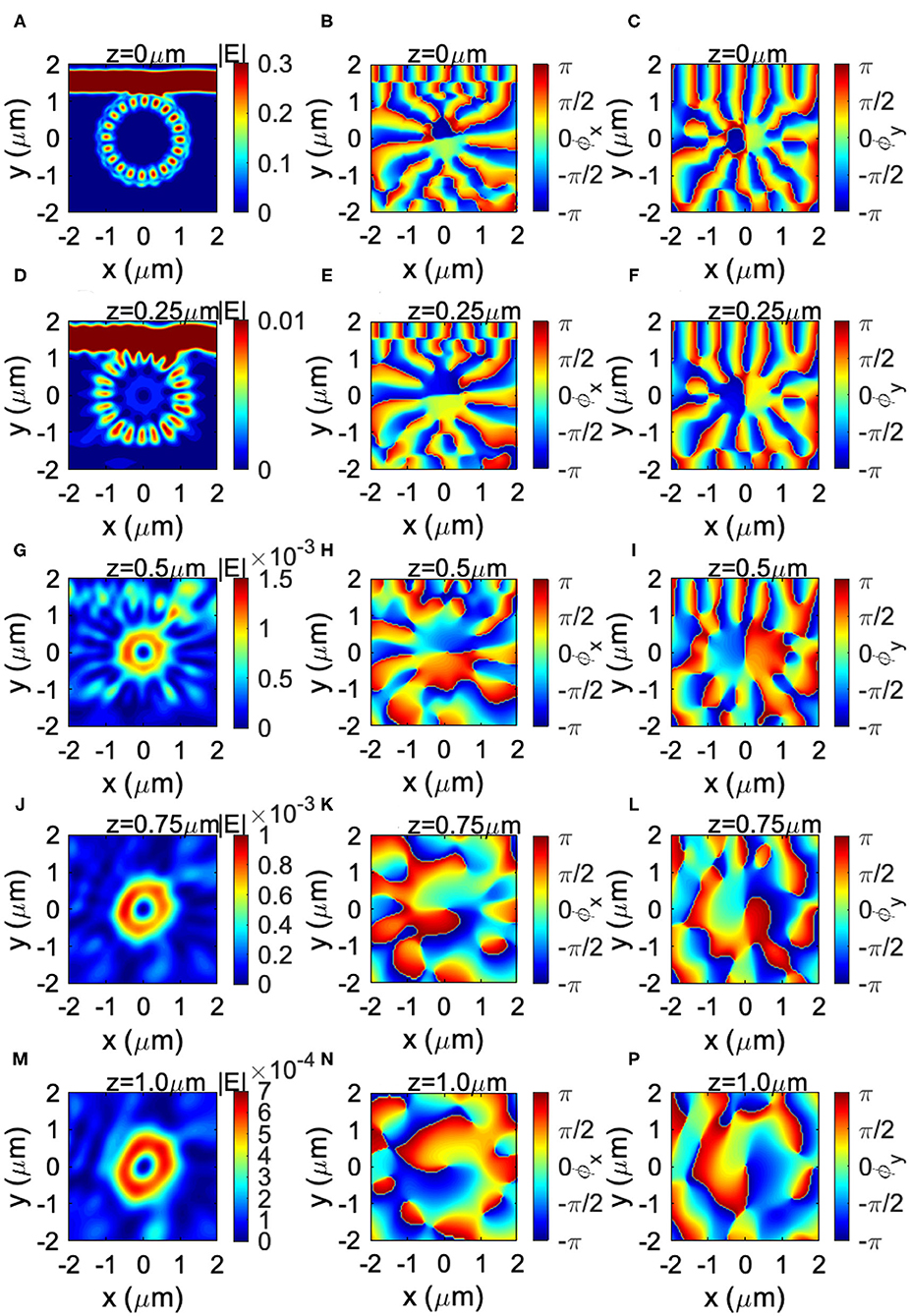
Figure 6. Generation of left vortex from the gear of N = 10. The input port 1 is used to inject photons to the waveguide. The mode profiles are obtained at z = 0, 0.25, 0.5, 0.75, and 1μm above the gear, which are shown in (A–C), (D–F), (G–I), (J–L), and (M–P), respectively. The amplitude and the phases ϕx = arg(Ex) and ϕy = arg(Ey) are shown in (A,D,G,J,M), (B,E,H,K,N), and (C,F,I,L,P), respectively.
2.4. Pancharatnam-Berry-Guoy's Phase
We have also considered the Pancharatnam-Berry-Guoy's phase on the generation of a vortex from the gear [26, 48, 73–76]. We considered the design of N = 10 (Figure 1B) and examined the evolution of mode profiles over the propagation along the +z direction (Figure 6). The input beam was injected from port 1, and it coupled evanescently to the gear. At the center of the waveguide at z = 0, the mode is circulating in the ring waveguide with OAM of m = −10. The phases of ϕx = arg(Ex) and ϕy = arg(Ey) show the right circulation over time. If we closely look at ϕx and ϕy inside the ring, there is no phase difference between them (ϕx ~ ϕy), consistent with the dominated radical polarization (Figures 2E,F) and thus we confirm s = 0. The beam is diffracted by the Bragg condition by the grating of the gear, and the mode was emitted vertically from the surface of the device. The direction of propagation is vertical but is slightly pointing inside the gear, since the grating is located only inside of the ring resonator. Consequently, the emitted beam is focused at around z = 0.5μm (Figure 6G), and defocused again (Figures 6H,M). It is important to recognize the presence of a node even at the focussed point (Figure 6G) to maintain the vortex. We can recognize that the mode gradually changed its shape to accommodate the left circulation with OAM of m′ = +1, which is opposite rotation with the circulation of m = −10 in the ring. We also confirmed that ϕy = ϕx−π/2 for a vortex at z ≥ 0.5μm, such that it is in the right-circularly polarized state.
We could also confirm the spatial rotation of ϕx and ϕy over z (Figures 6K,N,L,P), expected from ei(kz−ωt). The phase front evolution of z is opposite to t, such that the chiral rotation of the phase of the vortex over the space is opposite to the time evolution. The phase front has moved to the clock-wise (right) direction from Figures 6K,L to Figures 6N,P, respectively. This is in fact opposite to the left circulation of the vortex, and therefore, our interpretation of OAM and polarization of a vortex is consistent.
The schematic nature of the evolution of a vortex is shown in Figure 7. The chirality of the vortex cannot be changed upon the focussing, and the left circulation of the vortex is maintained. On the other hand, we had better to be careful about the geometrical phase facto of Pancharatnam-Berry-Gouy phase [19, 26, 73–76, 86], which is given by
where n is the radial quantum number of the Laguerre-Gauss mode, and z0 is the location of the focussing point [19, 48]. In the example of Figure 6, there is no node in the radial direction, except for the central core, and we can assign n = 0. In the absence of OAM (m = 0), ϕG would result in the phase change of the complex electric field, (Ex, Ey) → −(Ex, Ey). In our case, m′ = −1 will give another factor of −1, and therefore, we expect no change of the sign upon focussing for the far field (z → ∞).
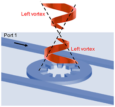
Figure 7. Pancharatnam-Berry-Gouy phase for a vortex generated from the gear. The contribution from the polarization would change the sign of the complex electric field, and the orbital angular momentum will also add to the phase change upon crossing of the focal point. The chirality of a vortex would not be changed upon focusing.
For the vortex beam with the higher order OAM, the Pancharatnam-Berry-Gouy phase factor depends on the parity of m. If |m| is odd, the contribution would vanish together with the contribution from the polarization, as we saw for m′ = −1. If |m| is even including m = 0, the phase change is expected upon crossing over the focal point. Therefore, the parity dependent interference is expected for a vortex, generated from the gear.
2.5. Far-Fields
We have also calculated far-fields and Stokes parameters in a polar coordinate (r, θ, ϕ) and in a cylindrical coordinate (r, ϕ, z), as shown in Figure 8. In a polar coordinate, the polar (Eϕ) and the azimuthal (Eϕ) components are obtained (Figures 8A–D). In particular, the phase of Eϕ is constant over the hemisphere (Figure 8D), showing the electric field is rotating with a fixed phase along the azimuthal direction. As noted before, the unit vector of azimuthal component depends on ϕ, (nϕ = nϕ(r, ϕ) = (−sin ϕ, cos ϕ, 0)), such that the fixed phase means the vectorial direction of azimuthal component is also changing the direction along the rotation.
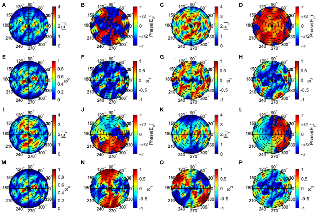
Figure 8. Far-fields and Stokes parameters of left vortex from the gear of N = 10. The input port 1 is used to inject photons to the waveguide. Far-fields and Stokes parameters are shown (A–H) in a polar coordinate (r, θ, ϕ) and (I–P) in a cylindrical coordinate (r, ϕ, z). The ring-shape of the mode in the near-field could not be sustained in far-fields (A,C,E,I), because our mode is not collimated. Consequently, the vortex is not well-defined in far-fields, while the phase is still rotated over the hemisphere (J,L), reflecting the original nature of a left-vortexed state. The polarization is also dominated by the right-circularly polarized component (H,P) with S3 ~ −1 for the high intensity region.
As shown in Figures 6, 7, our near-field mode profile is not collimated at all. Therefore, the vortex and associated OAM are not maintained in far-fields (Figures 8E,I,K), and the mode is spreading over the hemisphere. The intensity profiles are spreading over the polar angle of 10 to 40°. Nevertheless, the original nature of rotated phase is sustained, as shown in the rotated phases of ϕx (Figure 8J) and ϕy (Figure 8L), reflecting the left-vortexed nature in the near-field. The polarization of the mode is also reflecting the original mode in the near-field, and the right polarized component of S3 ~ −1 (Figures 8H,P) is dominated at the region of high intensities.
3. Poincaré Rotator
In this section, we discuss about our main results for the proposed Poincaré rotator (Figure 1A). As shown in the previous section, we could generate the left-vortexed state |L〉 by injecting photons from the port 1 of the Si wire waveguide. Due to the mirror symmetry between the port 1 and the port 2 together with the gear, we can generate the right-vortexed state |R〉, which is completely opposite chiral rotation to the left-vortex, by injecting photons from the port 2. The idea, here, is to inject from both ports after adjusting the relative amplitudes and phases of the injected beams, to generate an arbitrary vortexed state
in the hyper-Poincaré sphere. In modern Si photonic technologies, it is easy to control both amplitudes and phases by using integrated photonic circuits, such that we can control the superposition state in the hyper-Poincaré sphere.
3.1. Left and Right Vortices
First, we continue to evaluate the left-vortexed state, injected from the port 1. We have calculated azimuthal and radical components for |L〉 to obtain
Our numerical results support this picture, as shown in Figure 9. Both Eϕ and Er are almost constant over the location of the ring, where the intensity is maximized. The overall intensity of Eϕ is larger than Er, as explained by the dominant scattering of evanescent component of Eϕ at the internal grating [29]. The constant Eϕ does not preclude, however, the existence of the finite OAM of m′ = −1, as ϕx and ϕy are clearly rotating to the left over time. The rotated local spin component of |local spin〉 also gives rise to a contribute for Eϕ, since , which also gives a constant Eϕ along the direction of the rotation (ϕ).
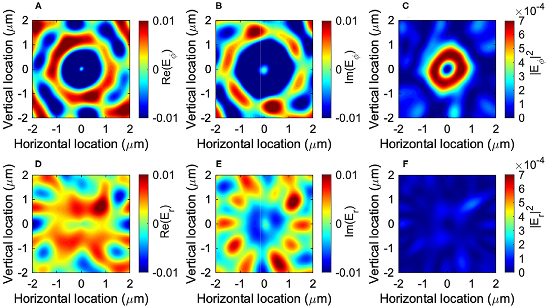
Figure 9. Left vortex generated from the gear of N = 10. The input port 1 is used to inject photons to the waveguide, and the mode profile is obtained at z = 1μm above the gear. (A) Real part, (B) imaginary part, and (C) intensity of the azimuthal complex electric field (Eϕ). (D) Real part, (E) imaginary part, and (F) intensity of the radial complex electric field (Er). Eϕ is almost constant over the ring, such that the mode is dominated by the azimuthal component.
Similarly, we have also calculated the mode profiles for the input from the port 2 to generate |R〉. We confirmed that the vortex is approximately expressed as
which means the generation of the right-vortexed state. As we expected the total angular momentum is zero, since it is the direct tensor product state with the left-circularly polarized state,
The conservation law of angular momentum upon the diffraction by the grating gear is given by
where s = 0, m = +10, N = −10, s′ = +1, and m′ = −1.
The corresponding azimuthal and radical components for |R〉 become
Numerical simulation completely supports this expectation, as shown in Figure 10. Eϕ (Figures 10A,B) changes its sign from the corresponding left-vortexed state (Figures 9A,B), while the relative phase between real and imaginary parts are maintained, which are determined by the location z of the detector, due to the simple phase evolution of ei(kz−ωt). On the other hand, Er for the right vortex (Figures 10D,E) shows the same phase with the corresponding Er for the left vortex (Figures 9D,E).
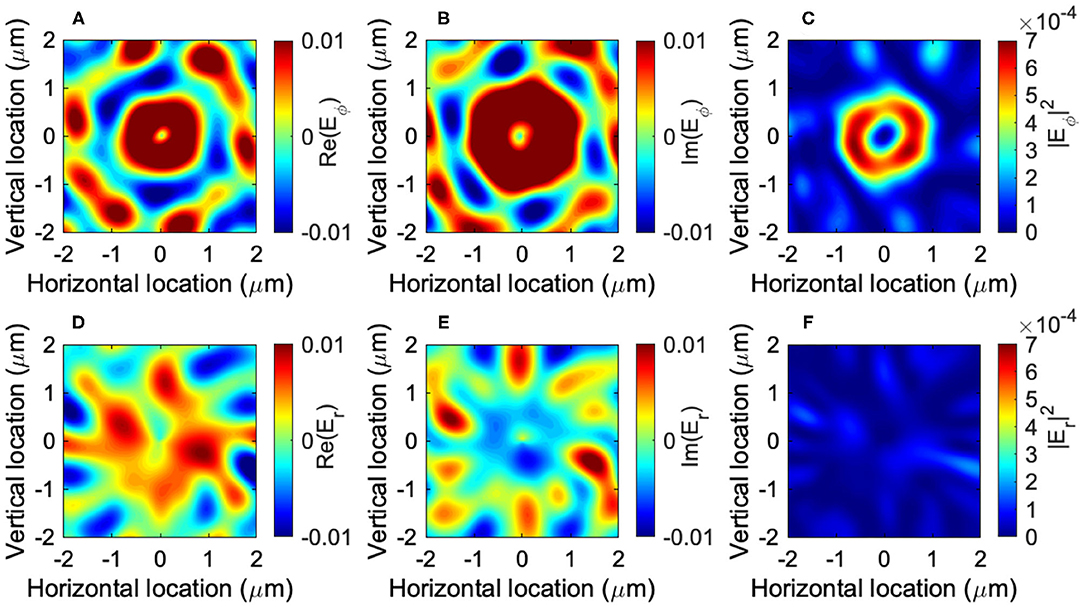
Figure 10. Right vortex generated from the gear of N = 10. The input port 2 is used to inject photons to the waveguide, and the mode profile is obtained at z = 1μm above the gear. (A) Real part, (B) imaginary part, and (C) intensity of the azimuthal complex electric field (Eϕ). (D) Real part, (E) imaginary part, and (F) intensity of the radial complex electric field (Er). Eϕ is pointing toward nϕ.
Therefore, we could prepare two orthogonal states of |L〉 and |R〉 simply by injecting photons from different ports. The orthogonality of the modes is guaranteed in 2-folds: one for the spin state as
and the other for OAM
We can also confirm the proper normalization as
3.2. Linearly Vortexed States
Now, we have prepared two states of |L〉 and |R〉, and we will discuss the superposition state among them. We assume that we can control the amplitudes and phases of two input beams from port 1 and port 2.
First, we will construct horizontally (|H〉) and vertically (|V〉) vortexed state. Considering the analogy to the polarization [48, 50, 51] and a spin 2-level system [5–7], we expect a unitary transformation
whose inverse transformation becomes
Therefore, the horizontally vortexed state is given by injecting photons in the same amplitude and the same phase into both ports, to get
Numerically results for the generated vortex of |H〉 are shown in Figure 11. It is important to be aware that the node is maintained at the center of the vortex. The mode profile of Ex is a dipole-like shape, aligned horizontally. Ex exhibits horizontal distribution, while Ey has a profile along the vertical direction. The difference is coming from the phase difference between real parts and imaginary parts, due to the difference in polarization. Therefore, the Ey component shows a conjugate vertically vortexed structure. If we would like to observe a purely horizontal vortexed state, we can use a polarizer to extract only the x component. Here, we shall call this mode as horizontally vortexed state, referring to the x component, while the y component is always its conjugate state. We have also calculated the local spin components (Figures 11E,F) and Stokes parameters (Figures 11I–L). The circularly polarized component was substantially compensated by the destructive superposition between left- and right-vortexed states.
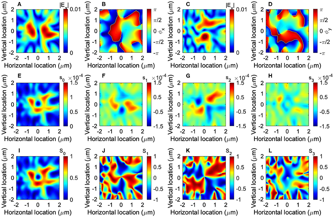
Figure 11. Horizontal vortex generated from the gear of N = 10. The input port 1 and 2 are used to inject photons to the waveguide, and two injected modes are in the same phase. The mode profile of a vortex is obtained at z = 1μm above the gear. (A) Real part and (B) imaginary part of the horizontal complex electric field (Ex). (C) Real part and (D) imaginary part of the vertical complex electric field (Ey). A horizontal dipole is recognized for Ex with a node at the center. (E–H) The local spin components (s0, s1,s2,s3), and (I–L) normalised Stokes parameters (S0, S1,S2,S3) are also shown. The circularly polarized component of s3 (H) was substantially reduced.
On the contrary, the vertically vortexed state (Figure 12) is given by
whose mode profile of Ex is a dipole-like shape, aligned vertically. The dipole-like shape of Ey is rotated 90°, which is in fact a conjugate horizontally vortexed state. It also has a node at the center.
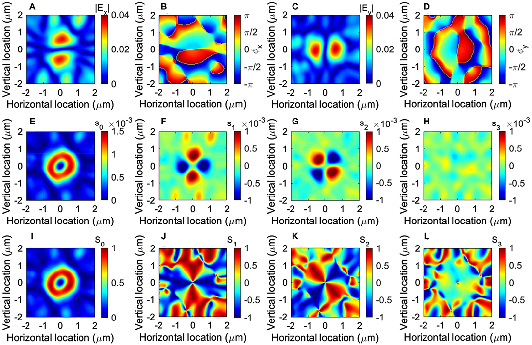
Figure 12. Vertical vortex generated from the gear of N = 10. The input port 1 and 2 are used to inject photons to the waveguide, and two injected modes are out of the phase. The mode profile of a vortex is obtained at z = 1μm above the gear. (A) Real part and (B) imaginary part of the horizontal complex electric field (Ex). (C) Real part and (D) imaginary part of the vertical complex electric field (Ey). A vertical dipole is recognized for Ex with a node at the center. (E–H) The local spin components (s0, s1,s2,s3), and (I–L) normalised Stokes parameters (S0, S1,S2,S3) are also shown.
If we include the spin state, these states correspond to a singlet state
and a triplet state
where we have used ↑ and ↓ instead of ↺ and ↻, respectively, and we have omitted to show ⊗ for simplicity. It is interesting to make a superposition state by using both internal spin degree of freedom and OAM. Alternatively, if we describe these states by the horizontally (↔) and the vertically (↕) polarized and vortexed states, we obtain a singlet state
and a triplet state
If we use the gear of N = 8, we could also generate another two states for the triplet states
For these states, the total sum of angular momentum between spin and OAM remain finite.
We are aware that the intensity of the intensity of |H〉 (Figure 11) is smaller than that of |V〉 (Figure 12). The reason is presumably because of our Si photonic waveguide design. All the modes in the waveguide is in the TE mode, which is vertically polarized along y direction, and there exists a tiny amount of the longitudinal component, due to the transverse nature of electro-magnetic waves. Regardless of the cylindrical symmetry of the gear, most of the photons are diffracted upwards by the grating without circulating the ring resonator. Therefore, the amount of the horizontally oscillating mode is reduced.
3.3. Diagonally Vortexed States
Next, we have considered the diagonal |D〉 (Figure 13) and the anti-diagonal |A〉 (Figure 14) vortices. In analogy to the polarization, we obtain
Numerical results for these states are shown in Figures 13, 14, respectively. A dipole is aligned diagonally in Ex for the diagonal vortex (Figure 13A), and anti-diagonally in Ex for the anti-diagonal vortex (Figure 14A). Phases of these states are not rotating clearly, such that the average OAM components along z vanish.
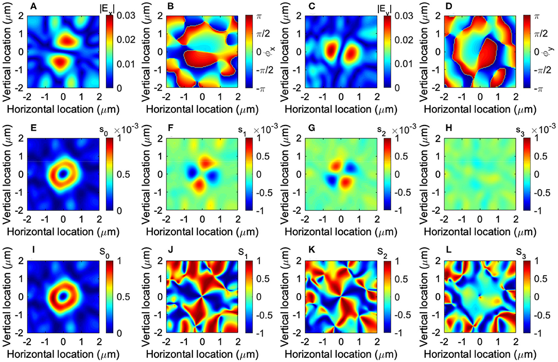
Figure 13. Diagonal vortex generated from the gear of N = 10. The input port 1 and 2 are used to inject photons to the waveguide, and the phase of the input 2 is π/2 ahead of the phase of the input 1. The mode profile of a vortex is obtained at z = 1μm above the gear. (A) The amplitude (|Ex|) and (B) the phase (ϕx) of the horizontal electric field Ex. (C) The amplitude (|Ex|) and (D) the phase (ϕy)of the horizontal electric field Ey. The phase is not obviously rotating any more. A diagonal dipole is recognized for Ex with a node at the center. (E–H) The local spin components (s0, s1,s2,s3), and (I–L) normalised Stokes parameters (S0, S1,S2,S3) are also shown.
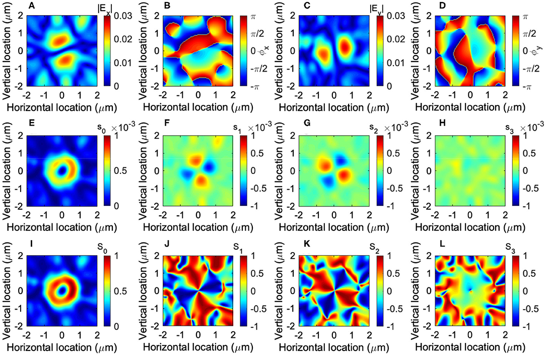
Figure 14. Anti-diagonal vortex generated from the gear of N = 10. The input port 1 and 2 are used to inject photons to the waveguide, and the phase of the input 1 is π/2 ahead of the phase of the input 2. The mode profile of a vortex is obtained at z = 1μm above the gear. (A) The amplitude (|Ex|) and (B) the phase (ϕx) of the horizontal electric field Ex. (C) The amplitude (|Ex|) and (D) the phase (ϕy)of the horizontal electric field Ey. An anti-diagonal dipole is recognized for Ex with a node at the center. (E–H) The local spin components (s0, s1,s2,s3), and (I–L) normalised Stokes parameters (S0, S1,S2,S3) are also shown.
If we include spin states, these states become
We also confirmed the conjugate nature of these states between Ex and Ey, as shown in Figures 13, 14.
3.4. Hyper-Poincaré Sphere
By extending above ideas, we can generate a superposition state of left- and right- vortexed state |Θ, Φ〉, defined by the polar angle of Θ and the azimuthal angle of Φ in a hyper-Poincaré sphere. Here, we consider a superposition state between left- and right-vortexed states, generated from the gear. In our design, the polarization degree of freedom is locked to a state, which is opposite to the direction of the rotation for a vortex. This is a significant limitation, compared to the hyper-Poincaré sphere, discussed by Milione et al. [28], and we cannot arbitrary change the polarization state for each vortex. Our hyper-Poincaré sphere is similar to the original proposal of Padgett and Courtial [21], and we would like to control by the gear coupled to the Si photonic wire waveguides (Figure 1).
In order to achieve it, the amplitude of the input 1 must be cos(Θ/2) and the amplitude of the input 2 must be sin(Θ/2), while the phase factor of the input 1 must be e−iΦ/2 and the phase factor of the input 2 must be eiΦ/2. This is easily achievable in a Si photonic platform [70, 71]. Therefore, the vortexed state can be controlled in our hyper-Poincaré sphere (Figure 15).
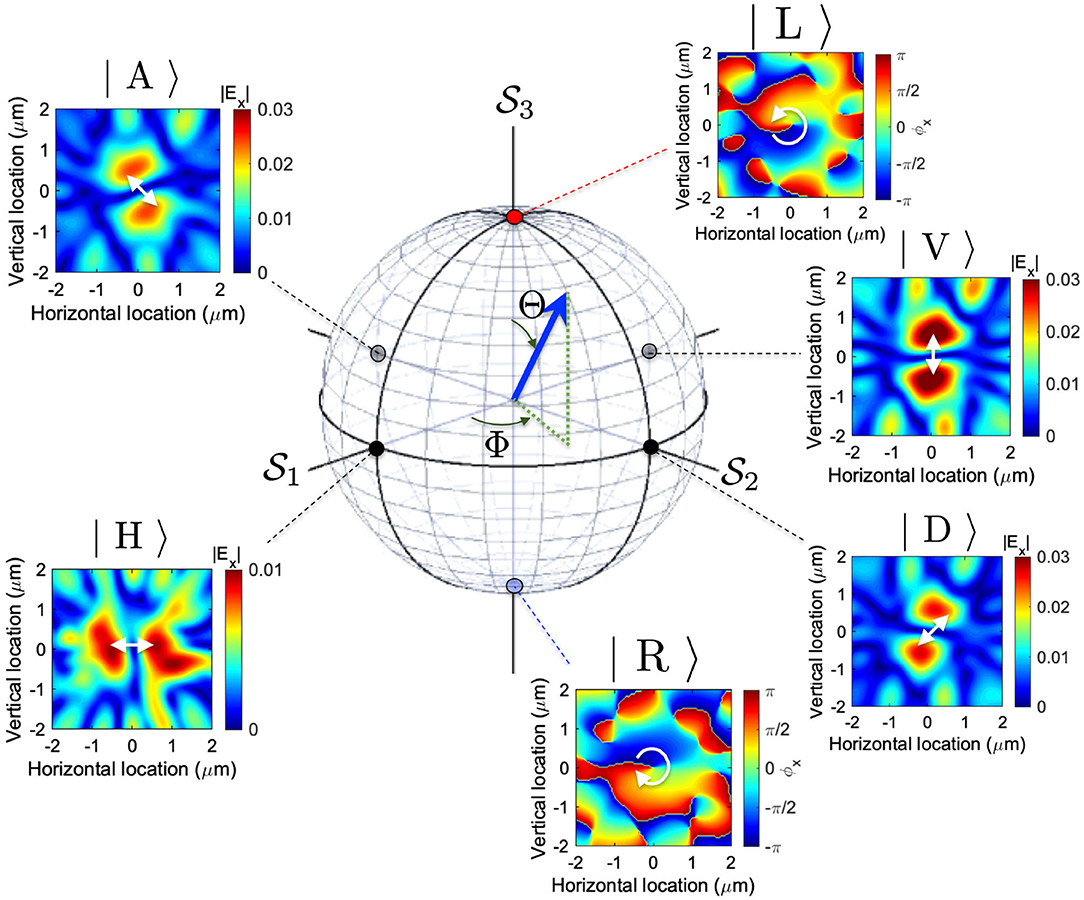
Figure 15. Hyper-Poincaré sphere for describing a quantum state of a vortex. The polar angle of Θ will control the amplitudes of the left and the right vortexed states, while the azimuthal angle of Φ will control the phase between these basis states. Insets show examples of various vortexed states simulated in this work.
In order to see how the vortexed state is changed, it is convenient to define the OAM operator defined by
where σi (i = 1,2, and 3) are the Pauli matrices, and these operators will act to the Hilbert space spanned by |L〉 and |R〉 as basis states. We consider the OAM average per particle, or we can multiply the density of photons in a coherent vortexed state, |Θ, Φ〉. These definitions are in a close analogy to the Stokes parameters for polarization [5–7, 10, 11, 48, 48, 50–52, 55–57, 60] toward the application to OAM [19, 21, 28, 36, 37, 52–54]. If we take the quantum mechanical average of these operators by |Θ, Φ〉, we obtain Stokes parameters for hyper-Poincaré sphere
and it is quite convenient to show these parameters in a 3-dimensional Poincaré sphere, as shown in Figure 15. The polar angle of Θ is related to the relative amplitude among two orthogonal modes, and the azimuthal angle of Φ corresponds to the phase difference between the two modes. Therefore, the proposed photonic gear with coupled two Si photonic wire waveguides is one of the practical systems to control these parameters in a compact on-chip module. Obviously, there are many other ways to control both amplitudes and phases to control the superposition state of left and right vortexed states.
4. Conclusion
We have proposed a silicon micro-gear coupled to two silicon photonic wire waveguide to control the vortexed state, generated out of the gear. We have shown the importance of the conservation law of the total angular momentum of spin and orbital angular momentum. The generated vortexed state is described by a tensor product of spin and orbit, and we proposed to achieve the superposition state between two orthogonal vortexed states. The amplitudes and the phases can be controlled by standard optical modulators, such that the control of the vortexed state is highly feasible. We believe Stokes parameters in the Poincareé sphere are one to the most important description to represent the quantum nature of spin state of photons. By extending Stokes parameters naturally to the orbital angular momentum in a hyper-Poincaré sphere is an important step to utilize OAM for various practical applications including quantum technologies.
Data Availability Statement
The raw data supporting the conclusions of this article will be made available by the authors, without undue reservation.
Author Contributions
The author confirms being the sole contributor of this work and has approved it for publication.
Funding
This work was supported by JSPS KAKENHI Grant Number JP 18K19958.
Conflict of Interest
SS is employed by Hitachi, Ltd., Tokyo, Japan.
Acknowledgments
The author would like to express sincere thanks to Prof I. Tomita for continuous discussions and encouragements.
References
1. Plank M. On the theory of the energy distribution law of the normal spectrum. Verhandl Dtsch Phys Ges. (1900) 2:237.
3. Tomonaga S. Quantum Mechanics: Volume I: Old Quantum Theory. Amsterdam: North-Holland Co. (1962).
4. Tomonaga S. Quantum Mechanics Volume II: New Quantum Theory. New York, NY: John Wiley & Sons (1966).
9. Nauenberg M. Max Planck and the birth of the quantum hypothesis. Am J Phys. (2016) 84:709. doi: 10.1119/1.4955146
10. Georgi H. Lie Algebras in Particle Physics: from Isospin to Unified Theories. Cambridge, MA: Westview Press (1999).
11. Pfeifer W. The Lie Algebras su(N): An Introduction. Berlin: Springer Basel AG (2003). doi: 10.1007/978-3-0348-8097-8
12. Weinberg S. The Quantum Theory of Fields: Foundations, Volume 1. Cambridge: Cambridge University Press (2005).
13. Lehner M. The Cambridge Companion to Einstein (Cambridge Companions to Philosophy). Cambridge: Cambridge University Press (2014).
14. Abrikosov AA, Gorkov LP, Dzyaloshinski IE. Methods of Quantum Field Thoery in Statistical Physics. New York, NY: Dover (1975).
16. Nagaosa N. Quantum Field Theory in Condensed Matter Physics. Berlin: Springer (1999). doi: 10.1007/978-3-662-03774-4
18. Altland A, Simons B. Condensed Matter Field Theory. Cambridge: Cambridge University Press (2010). doi: 10.1017/CBO9780511789984
19. Allen L, Beijersbergen MW, Spreeuw RJC, Woerdman JP. Orbital angular momentum of light and the transformation of Laguerre-Gaussian laser modes. Phys Rev A. (1992) 45:8185–9. doi: 10.1103/PhysRevA.45.8185
20. van Enk SJ, Nienhuis G. Commutation rules and eigenvalues of spin and orbital angular momentum of radiation fields. J Mod Opt. (1994) 41:963–77. doi: 10.1080/09500349414550911
21. Padgett MJ, Courtial J. Poincaré-sphere equivalent for light beams containing orbital angular momentum. Opt Lett. (1999) 24:430–2. doi: 10.1364/OL.24.000430
22. Allen L, Padgett MJ. The Poynting vector in Laguerre-Gaussian beams and the interpretation of their angular momentum density. Opt Commun. (2000) 184:67–71. doi: 10.1016/S0030-4018(00)00960-3
23. Marrucci L, Manzo C, Paparo D. Optical spin-to-orbital angular momentum conversion in inhomogeneous anisotropic media. Phys Rev Lett. (2006) 96:163905. doi: 10.1103/PhysRevLett.96.163905
24. Chen XS, Lü XF, Sun WM, Wang F, Goldman T. Spin and orbital angular momentum in gauge theories: nucleon spin structure and multipole radiation revisited. Phys Rev Lett. (2008) 100:232002. doi: 10.1103/PhysRevLett.100.232002
25. Lai WJ, Lim BC, Phua PB, Tiaw KS, Teo HH, Hong MH. Generation of radially polarized beam with a segmented spiral varying retarder. Opt Express. (2008) 16:15694–9. doi: 10.1364/OE.16.015694
26. Bliokh KY. Geometrodynamics of polarized light: Berry phase and spin Hall effecct in a gradient-index medium. J Opt A Pure Appl Opt. (2009) 11:094009. doi: 10.1088/1464-4258/11/9/094009
27. Ji X. Comment on “Spin and Orbital Angular Momentum in Gauge Theories: Nucleon Spin Structure and Multipole Radiation Revisited.” Phys Rev Lett. (2010) 104:039101. doi: 10.1103/PhysRevLett.104.039101
28. Milione G, Sztul HI, Nolan DA, Alfano RR. Higher-order Poincaré sphere, stokes parameters, and the angular momentum of light. Phys Rev Lett. (2011) 107:053601. doi: 10.1103/PhysRevLett.107.053601
29. Cai X, Wang J, Strain MJ, Johnson-Morris B, Zhu J, Sorel M, et al. Integrated compact optical vortex beam emitters. Science. (2012) 338:363–6. doi: 10.1126/science.1226528
30. Barnett SM, Cameron RP, Yao AM. Duplex symmetry and its relation to the conservation of optical helicity. Phys Rev A. (2012) 86:013845. doi: 10.1103/PhysRevA.86.013845
31. Sun J, Moresco M, Leake G, Coolbaugh D, Watts MR. Generating and identifying optical orbital angular momentum with silicon photonic circuits. Opt Lett. (2014) 39:5977–80. doi: 10.1364/OL.39.005977
32. Barnett SM, Allen L, Cameron RP, Gilson CR, Padgett MJ, Speirits FC, et al. On the natures of the spin and orbital parts of optical angualr momentum. J Opt. (2016) 18:064004. doi: 10.1088/2040-8978/18/6/064004
33. Barnett SM, Babiker M, Padgett MJ. Optical orbital angular momentum. Philos Trans R Soc A. (2016) 375:20150444. doi: 10.1098/rsta.2015.0444
34. Leader E, Lorcé C. The angular momentum controversy: what's it all about and does it matter? Phys Rep. (2014) 541:163–248. doi: 10.1016/j.physrep.2014.02.010
35. Bliokh KY, Rodríguez-Fortuño FJ, Nori F, Zayats AV. Spin-orbit interactions of light. Nat Photon. (2015) 9:796–808. doi: 10.1038/nphoton.2015.201
36. Naidoo D, Roux FS, Dudley A, Litvin I, Piccirillo B, Marrucci L, et al. Controlled generation of higher-order Poincaré sphere beams from a laser. Nat Photon. (2016) 10:327–32. doi: 10.1038/nphoton.2016.37
37. Liu Z, Liu Y, Ke Y, Liu Y, Shu W, Luo H, et al. Generation of arbitrary vector vortex beams on hybrid-order Poincaré sphere. Photon Res. (2017) 5:15–21. doi: 10.1364/PRJ.5.000015
38. Bliokh KY, Bekshaev AY, Nori F. Optical momentum, spin, and angular momentum in dispersive media. Phys Rev Lett. (2017) 119:073901. doi: 10.1103/PhysRevLett.119.073901
39. Bliokh KY, Bekshaev AY, Nori F. Optical momentum and angular momentum in complex media: from the Abraham-Minkowski debate to unusual properties of surface plasmon-polaritons. New J Phys. (2017) 19:123014. doi: 10.1088/1367-2630/aa8913
40. Erhard M, Fickler R, Krenn M, Zeilinger A. Twisted photons: new quantum perspectives in high dimensions. Light Sci Appl. (2018) 7:17146. doi: 10.1038/lsa.2017.146
41. Sotto M, Tomita I, Debnath K, Saito S. Polarization rotation and mode splitting in photonic crystal line-defect waveguides. Front Phys. (2018) 6:85. doi: 10.3389/fphy.2018.00085
42. Sotto M, Debnath K, Khokhar AZ, Tomita I, Thomson D, Saito S. Anomalous zero-group-velocity photonic bonding states with local chirality. J Opt Soc Am B. (2018) 35:2356–63. doi: 10.1364/JOSAB.35.002356
43. Sotto M, Debnath K, Tomita I, Saito S. Spin-orbit coupling of light in photonic crystal waveguides. Phys Rev A. (2019) 99:053845. doi: 10.1103/PhysRevA.99.053845
44. Dorney KM, Rego L, Brooks NJ, Romá JS, Liao CT, Ellis JL, et al. Controlling the polarization and vortex charge of attosecond high-harmonic beams via simultaneous spin-orbit momentum conservation. Nat Photon. (2019) 13:123–9. doi: 10.1038/s41566-018-0304-3
45. Moreau PA, Toninelli E, Gregory T, Aspden RS, Morris PA, Padgett MJ. Imaging Bell-type nonlocal behavior. Sci Adv. (2019) 5:eaaw2563. doi: 10.1126/sciadv.aaw2563
46. Ndagano B, Nape I, Cox MA, Rosales-Guzman C, Forbes A. Creation and detection of voctor vortex modes for classical and quantum communication. J Light Technol. (2018) 36:292–301. doi: 10.1109/JLT.2017.2766760
48. Yariv Y, Yeh P. Photonics: Optical Electronics in Modern Communications. Oxford: Oxford University Press (1997).
51. Gil JJ, Ossikovski R. Polarized Light and the Mueller Matrix Approach. London: CRC Press (2016).
52. Stokes GG. On the composition and resolution of streams of polarized light from different sources. Trans Camb Philos Soc. (1851) 9:399–416.
54. d Castillo GFT, García IR. The Jones vector as a spinor and its representation on the Poincaré sphere. Rev Mex Fis. (2011) 57:406–13.
55. Jones RC. A new calculus for the treatment of optical systems I. Description and discussion of the calculus. J Opt Soc Am. (1941) 31:488–93. doi: 10.1364/JOSA.31.000488
57. Fano U. A stokes-parameter technique for the treatment of polarization in quantum mechnics. Phys Rev. (1954) 93:121–3. doi: 10.1103/PhysRev.93.121
58. Collett E. Stokes parameters for quantum systems. Am J Phys. (1970) 38:563. doi: 10.1119/1.1976407
59. Luis A. Polarization distributions and degree of polarization for quantum Gaussian light fields. Opt Commun. (2007) 273:173–81. doi: 10.1016/j.optcom.2007.01.016
61. Luis A. Degree of polarization in quantum optics. Phys Rev A. (2002) 66:013806. doi: 10.1103/PhysRevA.66.013806
62. Pedrotti FL, Pedrotti LM, Pedrotti LS. Introduction to Optics. New York, NY: Pearson Education (2007).
63. Björk G, Söderholm J, Sánchez-Soto LL, Klimov AB, Ghiu I, Marian P, et al. Quantum degrees of polarization. Opt Commun. (2010) 283:4440–7. doi: 10.1016/j.optcom.2010.04.088
65. Courtial J, Dholakia K, Robertson DA, Allen L, Padgett MJ. Measurement of rotational frequency shift imparted to a rotating light beam possessing orbital angular momentum. Phys Rev Lett. (1998) 80:3217–9. doi: 10.1103/PhysRevLett.80.3217
66. Devlin RC, Ambrosio A, Rubin NA, Mueller JPB, Capasso F. Arbitrary spin-to-orbital angular momentum conversion of light. Science. (2018) 358:896–901. doi: 10.1126/science.aao5392
67. Al-Attili AZ, Kako S, Husain MK, Gardes FY, Higashitarumizu N, Iwamoto S, et al. Whispering gallery mode resonances from Ge micro-disks on suspended beams. Front Mat. (2015) 2:43. doi: 10.3389/fmats.2015.00043
68. Shao Z, Zhu J, Chen Y, Zhang Y, Yu S. Spin-orbit interaction of light induced by transverse spin angular momentum engineering. Nat Commun. (2018) 9:926. doi: 10.1038/s41467-018-03237-5
69. Zhang Z, Qiao X, Midya B, Liu K, Sun J, Wu T, et al. Tunable topological charge vortex microlaser. Science. (2020) 368:760–3. doi: 10.1126/science.aba8996
71. Saito S, Tomita I, Sotto M, Debnath K, Byers J, Al-Attili AZ, et al. Si photonic waveguides with broken symmetries: applications from modulators to quantum simulations. Jpn J Appl Phys. (2020) 59:SO0801. doi: 10.35848/1347-4065/ab85ad
72. Guan B, Scott RP, Qin C, Fontaine NK, Su T, Ferrari C, et al. Free-space coherent optical communication with orbital angular, momentum multiplexing/demultiplexing using a hybrid 3D photonic integrated circuit. Opt Express. (2013) 22:145–56. doi: 10.1364/OE.22.000145
73. Pancharatnam S. Generalized theory of interference, and its applications. Proc Indian Acad Sci Sect A. (1956) XLIV:398–417. doi: 10.1007/BF03046095
74. Berry MV. Quantual phase factors accompanying adiabatic changes. Proc R Sco Lond A. (1984) 392:45–57. doi: 10.1098/rspa.1984.0023
75. Tomita A, Cao RY. Observation of Berry's topological phase by use of an optical fiber. Phys Rev Lett. (1986) 57:937–40. doi: 10.1103/PhysRevLett.57.937
76. Simon R, Mukunda N. Bargmann invariant and the geometry of Güoy effect. Phys Rev Lett. (1993) 70:880–3. doi: 10.1103/PhysRevLett.70.880
77. Debnath K, Thomson DJ, Zhang W, Khokhar AZ, Littlejohns C, Byers F, et al. All-silicon carrier accumulation modulator babsed on a lateral metal-oxide-semiconductor capacitor. Photon Res. (2018) 6:373–9. doi: 10.1364/PRJ.6.000373
78. Lee BG, Small BA, Bergman K, Xu Q, Lipson M. Transmission of high-data-rate optical signals through a micrometer-scale silicon ring resonator. Opt Lett. (2006) 31:2701–6. doi: 10.1364/OL.31.002701
79. Bogaerts W, Heyn PD, Vaerenbergh TV, Vos KD, Selvaraja SK, Claes T, et al. Silicon microring resonators. Laser Photon Rev. (2012) 6:47–73. doi: 10.1002/lpor.201100017
80. Serrano-Núñez MA, Shoji Y, Mizumoto T. Giant Faraday rotation of cobalt ferrite thin films deposited on silicon substrates for silicon photonic nonreciprocal device applications. Appl Phys Express. (2020) 13:062002. doi: 10.35848/1882-0786/ab8b52
81. Cao QT, Wang H, Dong CH, Jing H, Liu RS, Chen X, et al. Experimental demonstration of spontaneous chirality in a nonlinear microresonator. Phys Rev Lett. (2017) 118:033901. doi: 10.1103/PhysRevLett.118.033901
82. Almeida VR, Barrios CA, Panepucci RR, Lipson M. All-optical control of light on a silicon chip. Nature. (2004) 431:1081–4. doi: 10.1038/nature02921
85. Joannopoulos JD, Johnson SG, Winn JN, Meade RD. Photonic Crystals: Molding the Flow of Light. New York, NY: Princeton University Press (2008). doi: 10.1515/9781400828241
Keywords: orbital angular momentum, vortex, Poincaré sphere, stokes parameter, silicon photonics
Citation: Saito S (2021) Poincaré Rotator for Vortexed Photons. Front. Phys. 9:646228. doi: 10.3389/fphy.2021.646228
Received: 25 December 2020; Accepted: 23 February 2021;
Published: 24 March 2021.
Edited by:
Guangcan Guo, University of Science and Technology of China, ChinaCopyright © 2021 Saito. This is an open-access article distributed under the terms of the Creative Commons Attribution License (CC BY). The use, distribution or reproduction in other forums is permitted, provided the original author(s) and the copyright owner(s) are credited and that the original publication in this journal is cited, in accordance with accepted academic practice. No use, distribution or reproduction is permitted which does not comply with these terms.
*Correspondence: Shinichi Saito, c2hpbmljaGkuc2FpdG8ucXRAaGl0YWNoaS5jb20=