Abstract
In recent years, lensfree on-chip microscopy has developed into a promising and powerful computational optical microscopy technique that allows for wide-field, high-throughput microscopic imaging without using any lenses. However, due to the limited pixel size of the state-of-the-art image sensors, lens-free on-chip microscopy generally suffers from low imaging resolution, which is far from enough to meet the current demand for high-resolution microscopy. Many pixel super-resolution techniques have been developed to solve or at least partially solve this problem by acquiring a series of low-resolution holograms with multiple lateral sub-pixel shifting or axial distances. However, the prerequisite of these pixel super-resolution techniques is that the propagation distance of each low-resolution hologram can be obtained precisely, which faces two major challenges. On the one hand, the captured hologram is inherent pixelated and of low resolution, making it difficult to determine the focal plane by evaluating the image sharpness accurately. On the other hand, the twin-image is superimposed on the backpropagated raw hologram, further exacerbating the difficulties in accurate focal plane determination. In this study, we proposed a high-precision autofocusing algorithm for multi-height pixel-super-resolved lensfree on-chip microscopy. Our approach consists of two major steps: individual preliminary estimation and global precise estimation. First, an improved critical function that combines differential critical function and frequency domain critical function is proposed to obtain the preliminary focus distances of different holograms. Then, the precise focus distances can be determined by further evaluating the global offset of the averaged, low-noise reconstruction from all backpropagated holograms with preliminary focus distances. Simulations and experimental results verified the validity and effectiveness of the proposed algorithm.
1. Introduction
In recent years, high-resolution wide-field optical imaging has become a valuable tool in various biomedical applications such as cell counting [1], cell morphology measurement [2], and optical microscopy techniques that require low-cost and compact imaging systems [3–5]. Nevertheless, it is difficult for traditional microscopic imaging technology to satisfy the large field-of-view and high-resolution at the same time. The recently developed lensfree on-chip microscopy provides a new opportunity to process high-resolution and large field-of-view images, which has the advantages of small size, low cost, and excellent performance [6–14]. Lensfree on-chip microscopy reconstructed the image of a specimen based on the interference patterns created by the diffracted object. To achieve wide-field imaging, the samples are placed as close as possible to the imaging sensor [13, 14]. In this case, the resolution of the reconstructed image is limited by the pixel size of the sensor instead of the system numerical aperture, which results in the system resolution does not meet the needs of current applications. In order to solve this problem, super-resolution algorithms that process a series of low-resolution holograms have been applied to lensfree imaging [15–18]. Many related studies have been proposed and can be classified as: two-dimensional movement of light sources by mechanical structures [19], tightly distributed fiber arrays [14], multi-height super-resolution algorithm [11], different illumination wavelengths [18], different illumination angles [20], and so on.
Furthermore, to improve the data processing efficiency of super-resolution and twin-image removal, related research has been proposed. Luo et al. [12] proposed a propagation phasor approach, which combines pixel super-resolution and phase retrieval techniques. Zhang et al. [8] proposed an adaptive pixel-super-resolved lensfree imaging (APLI) method based on the Z-axis scanning holograms. Both of these methods require a series of holograms of different heights. In the process, the sample-to-sensor distances must be accurately determined, otherwise, it will directly affect the final super-resolution image resolution. For example, an error of 1 μm in the reconstruction distance directly results in the absence of information corresponding to group 9 of 1951 USAF resolution test target for typical lensfree on-chip systems [8]. Therefore, accurate autofocusing is an essential step in the actual experimental measurement of lensfree super-resolution microscopy.
In the past decades, various autofocusing methods have been proposed for digital holography [21–31]. Automatic evaluation function is the primary consideration of image definition, which is mainly determined from the spatial domain and the frequency domain. Compared with the defocused blurred image in the spatial domain, the focused image has obvious sharpened edges. Based on the concept, the Sobel operator [26], Laplace operator [27], and the total sum of gradient [23] have been used as evaluation function. In the frequency domain, the focused image has more high frequency components than the blurred image, so the high frequency component value can be used as the focus evaluation standard, such as bandpass-filtered power spectrum [27]. In addition, evaluation functions based on other models have appeared, such as differential critical function (DIF) [23], self-entropy [28], spectral L1 norms [29] etc. However, the above algorithms are difficult to directly apply to the autofocusing of multi-height pixel-super-resolved lensfree on-chip imaging. The main problems are as follows: (1) Due to the use of lensfree microscopy, the sharp edge of the focused image is not obvious, so it is difficult to judge the focus directly. (2) The lensfree on-chip microscopy is inevitably interfered by twin-image, which affects the accuracy of evaluation function. (3) In super-resolution imaging, each hologram of different heights needs to be accurately reconstructed, which requires high accuracy of the focusing distance of each plane. Currently, there is no specific and effective technology to achieve high-precision autofocusing under the influence of twin-image for lensfree on-chip imaging.
In this paper, a high-precision autofocusing method is proposed based on the multi-height pixel-super-resolved lensfree on-chip microscopy. The proposed method can be divided into two steps: individual preliminary estimation and global precise estimation. First, an improved differential critical function (SDIF) has been proposed to obtain the approximate focus distances of different height planes, which combines differential critical function and frequency domain autofocus. In order to solve the problem that the DIF value will remain flat near the peak or valley, we introduced frequency domain autofocus to improve the sensitivity of DIF. Then, the intensity or phase image of different heights is synthesized into a high-resolution reference without twin-image. we regard a series of holograms of different heights as a whole, and a high-resolution reference image can be obtained by consistently varying the reconstructed distances of the holograms at different heights. we transform the problem of focusing on different planes into a problem of solving the optimal solution of the overall system. Last, by searching for the extremum of the synthesized image, we can determine the overall offset and get the final reconstruction distance sequence. Through the proposed method, we can more accurately determine the focus distances of different plane heights and improve the accuracy of super-resolution based on the multi-height pixel-super-resolved lensfree on-chip imaging. The structure of the paper is as follows: Basic introduction of lensfree on-chip holography imaging and theoretical knowledge of proposed methods are carried out in section 2. Simulations are carried out in section 3. The section 4 shows the experimental setup and experimental results for amplitude-contrast or phase-contrast objects. Conclusions are given in the in section 5.
2. Methodology
2.1. The Basic Principle of Lensfree On-Chip Holography
First, we introduce the basic recording and numerical reconstruction principles of lensfree on-chip holography, which is essentially in-line digital holographic imaging. When the light source with sufficient spatial and temporal coherence illuminates the sample, the hologram H(x, y) is formed by the interference between the scattered light O(x, y) on the sample and the unscattered background light R(x, y), which can be expressed as:
Where, r(x, y) and o(x, y) are the amplitude information of the reference light and the object light, respectively, and ϕ(x, y) is the phase information of the object light wave. Through the angular spectrum algorithm, the light intensity and phase information of the object light wave can be obtained, which can be expressed as:
Where F and F−1 denote the Fourier transform and the inverse Fourier transform, respectively. G(fx, fy, z) is the optical transfer function in the frequency domain. λ is the wavelength of the light source, z1 is the distance from the sample to the sensor plane. For lensfree on-chip microscopy, in order to expand the field of view and improve the resolution, the distance between the sample and the sensor is very small (z1 ≪ z2) as shown in Figure 1A. The typical distance of sample-to-sensor is 400–1,000 μm. Since the system does not have a microscope objective, it is necessary to propagate the hologram back to the focal plane. In actual operation, the distance between the sample and the sensor is usually obtained by the autofocusing algorithm. Based on that, the maximum field of view is similar to the working area of the image sensor, and the maximum image resolution is approximately the resolution of the image sensor. Due to the limitation of the pixel size of the sensor, the resolution of lensfree on-chip holography is insufficient. Reconstruction based on multiple heights is an effective super-resolution reconstruction method, which can also remove twin-image at the same time. The triangle, ellipse, and pentagram in Figure 1B represent grid points of captured holograms on different planes, respectively, and each of the low-resolution images contains similar and complementary information. The super-resolution reconstruction combines all these new information into one image to obtain a high-resolution image. The most common matrix notations used to formulate the general super-resolution model in the pixel domain can be defined as [32]:
Where, the matrix Fk is the geometric motion operator between the high-resolution (HR) frame X and the low-resolution (LR) frame Yk. The camera's point spread function (PSF) is modeled by the blur matrix Hk, and matrix Dk represents the decimation operator. Vk is the system noise and N is the number of available LR frames. Based on this, the problem of obtaining a high-resolution image from a set of low-resolution images can be attributed to the solution of the following equation:
In the process of super-resolution, we need to get a series of low-resolution holograms with different distances of sample-to-sensor. However, the reconstruction distance of each hologram is difficult to determine accurately in actual experiments, which directly affects the resolution of the final super-resolved image. Therefore, accurate autofocusing is an essential step in the lensfree on-chip super-resolution imaging.
Figure 1
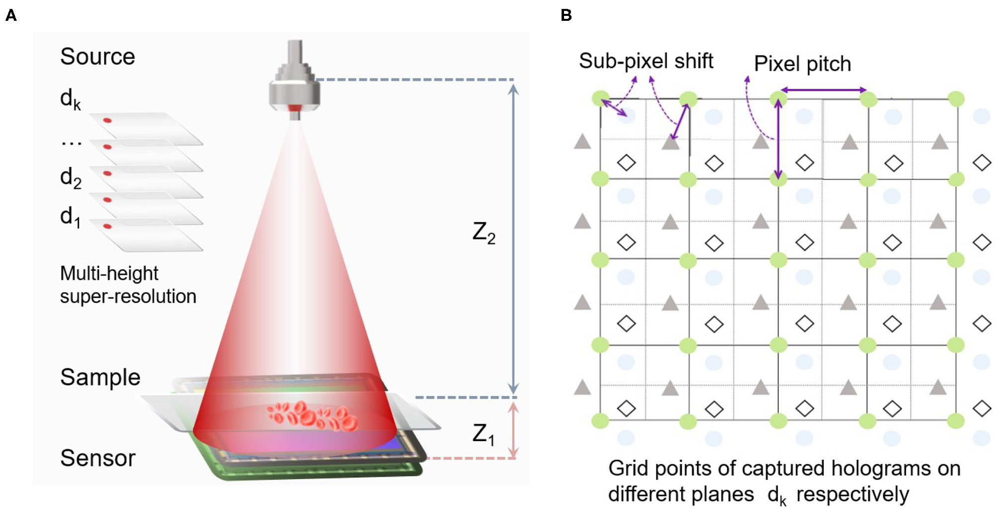
(A) The schematic diagram of the lensfree on-chip holography with multi-distances of sample-to-sensor. (B) Sub-pixel shifts among captured images on multi-height planes.
2.2. The Proposed Critical Function
First, we initially determine the reconstruction distances for different height holograms. In the autofocusing algorithm, the key issue is to find a high-precision critical function, which directly affects the subsequent resolution accuracy problem. Considering the influence of twin-image, the differential critical function could be more suitable as the critical function. By making a difference between adjacent reconstructed images, the influence of noise such as twin-image can be reduced to a certain extent. The plane in focus can be determined by searching for the minimum value of differential critical function for amplitude-contrast objects or the maximum value for amplitude-contrast objects. Therefore, the reconstruction distance can be preliminarily determined by searching the extreme value in the initial interval [z1, z2] with the step size Δ, as shown in the following formula:
where l = 0, 1, ..., (z2 − z1)/Δ − 1. ΔŪ is the light intensity or phase depending on the type of object. It should be emphasized that for traditional the differential critical function, usually only rely on the intensity. The initial reconstruction distance can be determined by finding the minimum value for the amplitude-contrast object or the maximum value for the phase-contrast object. When the need for focusing accuracy is not very high, the position in focus can be approximated by the above method. However, when the need for focusing accuracy is high, it is more accurate to use intensity as the evaluation data for amplitude-contrast objects, and phase as evaluation data for phase-contrast objects. Although noise interference can be reduced to a certain extent through the critical function of differential, this discriminant factor is insufficient for high-precision focusing sensitivity. Especially when the step size Δ is very small, it is easy to have multiple extreme values. The corresponding simulations and experiments are in the following sections.
In order to solve this problem, the frequency domain critical factor is introduced. The main reasons can be attributed to the following aspects: The critical factor in the frequency domain is more sensitive to high-frequency information. However, if the hologram is directly reconstructed, the high-frequency information generated by the noise will make the frequency domain critical factor unstable or make errors. When the interference of twin-image is weakened, the frequency domain focusing has higher accuracy and stability. Actual simulations and experiments below verify the reliability and stability of the proposed critical factor. Therefore, we can define the criteria function SDIF as shown in the following formula:
Where DCT is the Fast Cosine Fourier Transform. M,N are the size pixels of the image. By calculating the value of SDIF at different position intervals, we can preliminarily determine the focus distances of different holograms based on the extreme value of SDIF.
2.3. Individual Preliminary Estimation and Global Precise Estimation
According to sections 2.1, 2.2, the reconstruction distances for different height holograms can be initially obtained. However, the resulting reconstructed image still has the effect of the twin-image and it is difficult to further determine the focal distance by a single evaluation factor. Therefore, to ensure the overall resolution of the reconstructed images, we synthesize the reconstructed images of different heights into a single reconstructed image. Based on this, the problem of focusing on different planes is transformed into the problem of solving the optimal solution of the whole system. There are two main issues that need to be addressed. Firstly, when combining reconstructed images of different heights into a whole, consideration must be given to eliminating the effects of twin-image and increasing the resolution of the reconstructed image. Secondly, the current process is not the same as the super-resolution algorithm. It is simply a pre-processing process for super-resolution to obtain the exact reconstructed distance. Therefore, this process should not take too much time. In this paper, we use the weighted average method, which can be expressed as:
Where K is the number of hologram sequences with different heights and dk is the corresponding initial reconstruction distance based on sections 2.1, 2.2. In the actual operation of multi-height lensfree super-resolution, the defocus range of the reconstruction distance is very small, and the high-frequency detail information of the reconstructed image will change significantly. On the whole, by summing and averaging the reconstructed images of different heights, the noise such as twin-image can be quickly reduced and the high-frequency information of the reconstructed image can also be improved. In actual operation, there are two problems that need special attention. On the one hand, it should be emphasized that in the actual operation of lensfree on-chip holography, the smaller the distance between the sample and the sensor, the more high-frequency information of the object. Therefore, in the summation process, α is introduced as a weighting factor. In this article, α is set to 1/k for simplicity, and theoretical relationships are more complex. On the other hand, when the sample or sensor is displaced in the axial direction, lateral displacement will inevitably occur in the X-Y plane, which will cause serious spatial domain aliasing. In this article, the cross-correlation sub-pixel shift method [33] is applied to correct lateral position errors. The reconstructed image closest to the sensor is used as the initial position reference. The reconstructed image after correction Ūcor(xshift, yshift) can be expressed as:
Where, (xshift, yshift) is the sub-pixel shift calculated by the cross-correlation method. (fx, fy) is the frequency domain coordinates. Therefore, Equation (11) can be rewritten as:
So far, we have obtained a preliminary set of reconstructed distance sequences of holograms and synthetic reconstructed images with less noise and more detailed information. We will then evaluate the synthetic reconstructed images to further determine more accurate reconstructed distances. The reconstructed distance sequence [d1, d2, ......, dk] will also be processed as a whole. Now we can further narrow the interval to [z3, z4](z1 < z3 < z4 < z2)with a smaller step size Δ1. Every time the reconstruction distance sequence changes as a whole, a new synthetic reconstruction image can be obtained. Then, based on sections 2.1, 2.2, the focused position of synthetic reconstruction image can be determined by searching the extreme value in the interval [[z3, z4]] with the step size Δ1. Assuming that the overall moving distance sequence is [d1, d2, ......, dk], the final reconstructed distance sequence D can be expressed as:
3. Simulations
In this section, we will perform simulation experiments to verify the principles of the proposed algorithm. According to the proposed algorithm as shown in Figure 2, the whole simulation is divided into two parts: the individual preliminary estimation of the reconstructed distance sequence and the global precise estimation. The simulation procedure is described as follows. First, we simulate an object with amplitude contrast which has a size of 520×520 pixels. The object is propagated to 10 planes by an angular spectrum algorithm. The closest distance between the hologram and the sensor is 500 μm, and the distance interval of each hologram is set to 20 μm. In the actual lensfree on-chip holography, the resolution is limited by the pixel size, so in the simulation experiment, the object light wave is also down-sampled [34] with a down-sampling factor of 4 as shown in Figure 3.
Figure 2
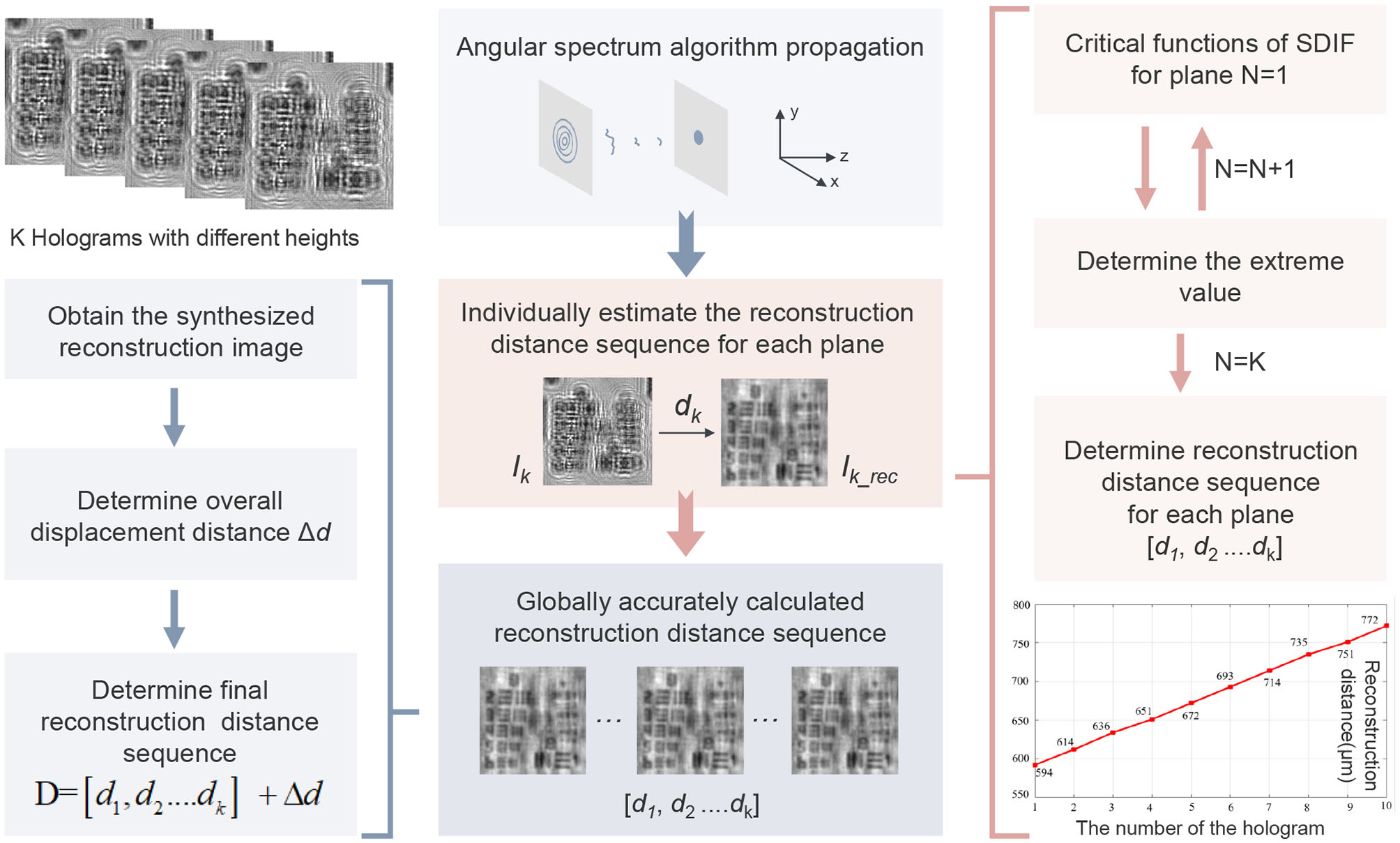
Flow chart of the proposed autofocusing algorithm for lensfree on-chip holography.
Figure 3
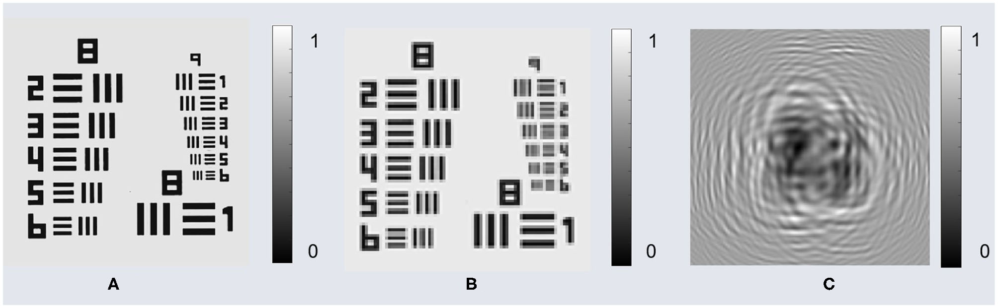
Simulation sample and corresponding hologram. (A) Original high-resolution intensity. (B) Low-resolution intensity after down sampling. (C) Simulated hologram based on the low-resolution intensity.
3.1. The Individually Preliminary Estimation
In this section, we need to initially calculate the reconstruction distances for holograms of different heights. To verify the accuracy of the proposed critical functions, we used the closest hologram to the sensor to calculate the reconstruction distance (d1= 500 μm). We calculated the critical functions for DIF and SDIF separately. The initial reconstruction distance range is [485, 515] μm with the interval of Δ2 = 0.5 μm as shown in Figure 4A. By calculating the minimum value of critical functions, we can see that the reconstruction distance is about 500 μm for the critical functions of DIF and the SDIF. In order to determine the reconstruction distance more accurately, we shorten the interval and step size with the reconstruction distance range of [498, 503] μm, the interval of Δ2 = 0.5 μm. As can be seen from Figure 4B, critical functions of DIF changes smoothly in the range of [499, 501] μm, and has no obvious minimum value. However, the critical functions of SDIF can also clearly determine the minimum value of 500.5 μm in the range of [500, 501] μm.
Figure 4
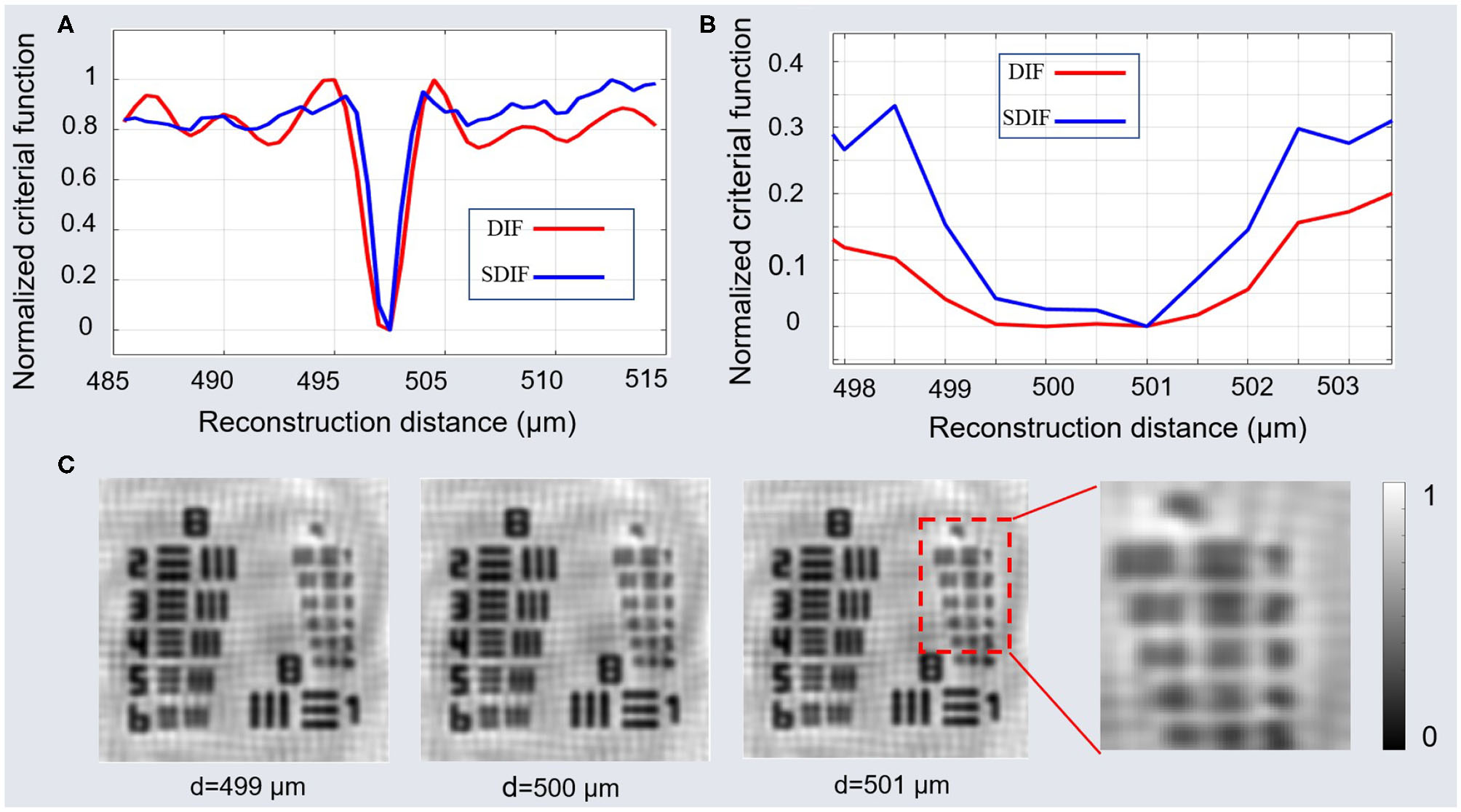
Individually simulation results: (A) Normalized criterial function with step of 10 μm. (B) Normalized criterial function with step of 0.5 μm. (C) Reconstructed intensity at different reconstruction distances.
3.2. The Global Precise Estimation
For lensfree on-chip holography, the reconstruction distance accuracy directly affects the resolution of high-frequency information. Figure 4C shows the reconstructed intensity at different reconstruction distances. The system has no lens, and the reconstructed image is affected by the twin-image. At this point, it is difficult to directly determine the focus distance of the high frequency information based on a single low-resolution hologram.
Based on section 3.1, we can get the reconstruction distance sequence [500.5, 520.5, 540.5, 560.5, 580.5, 600.5, 620.5, 640.5, 660.5, 680.5] μm corresponding to different height holograms. Then, the synthesized intensity can be obtained by Equations (12) and (13) as shown in Figure 5A. It can be clearly seen that the synthesized intensity has clearer detailed information compared with the low-resolution light intensity. Every time the entire distance sequence moves Δd, a new synthesized intensity image can be obtained. In this case, the proposed method transforms the problem of focusing on different planes into a problem of solving the optimal solution of the overall system. By calculating the minimum value of SDIF for synthesized intensity images, the overall displacement distance Δd can be obtained as shown in Figure 5B. In the global precise estimation, the range of Δd is [−5.0, 2.0] μm and the interval is 0.5 μm. It is easy to obtain the overall displacement distance minimum Δd = −0.5 μm. Therefore, the final reconstruction distance sequence can be determined D = [d1, d2......dk] + Δd = [500.0, 520.0, 540.0, 560.0, 580.0, 600.0, 620.0, 640.0, 660.0, 680.0] μm. Last, the high-resolution intensity image can be obtained by the APLI algorithm as shown in Figure 5C.
Figure 5
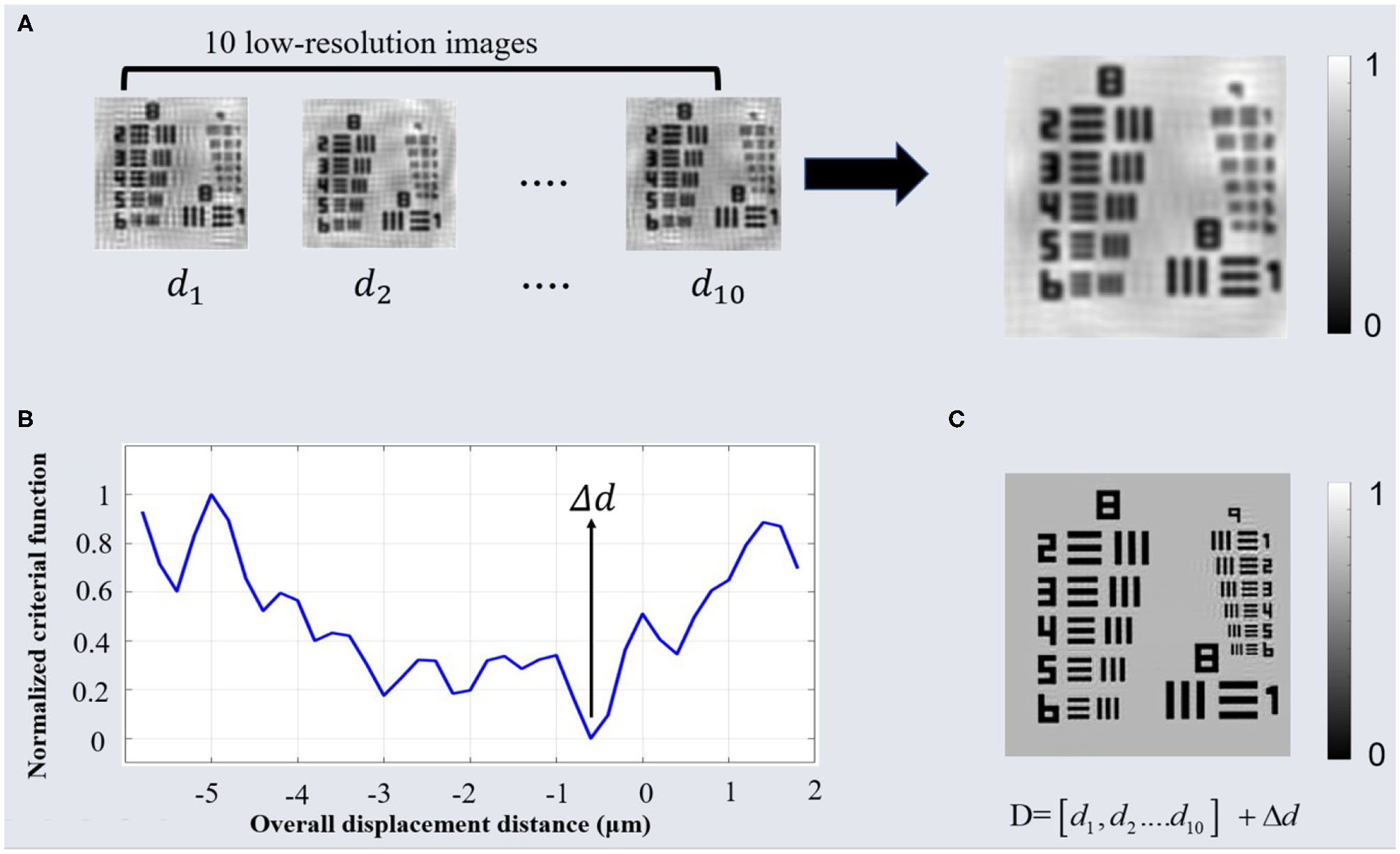
Global simulation results: (A) The synthetic intensity based on low-resolution intensity with the reconstructed distance sequence [d1, d2.......d10]. (B) Normalized criterial function for the synthetic intensity with different overall displacement distance. (C) The high-resolution intensity based on APLI algorithm by the reconstructed distance sequence D.
4. Experiment
4.1. Experimental Setup
To identify the robustness and adaptability of the proposed method, we respectively conducted experiments on an amplitude-contrast object and a phase-contrast object, respectively, based on the lensfree on-chip holography system as shown in Figure 6. The system mainly contains four parts: a single mode fiber-coupled light source with the wavelength of 661.5 nm (LP660-SF20, Thorlabs, the United States), a monochrome imaging device with 3,872×2,764, and pixel size of 1.67 μm (DMM 27UJ003-ML, the imaging source, Germany), displacement platform for sample and the motor drive hardware. In the system, the distance between the light source and the sample is about 20 cm. The distance between the sensor and the sample is between 500 and 1,000 μm, and the distance can be adjusted by the motor drive hardware. M1, M2, M3 are fixed reflecting prisms and M4 is a reflecting prism that can be moved around the x and y axes. The sensor is fixed to a displacement table that can be moved precisely vertically by means of a motor drive. However, in actual experiments, when the z-axis distance is adjusted by the motor drive hardware, there is usually a deviation between the preset distance and the actual distance. In addition, during the movement of the z-axis, there will usually be horizontal displacement due to mechanical vibration. It should be emphasized that only the z-axis height needs to be adjusted in our experiments, and there is no need to change the x-axis and y-axis distances.In the following experiment, we will set the hardware program to raise the sample stage by 20 μm in turn and collect 10 low-resolution holograms as experimental samples.
Figure 6
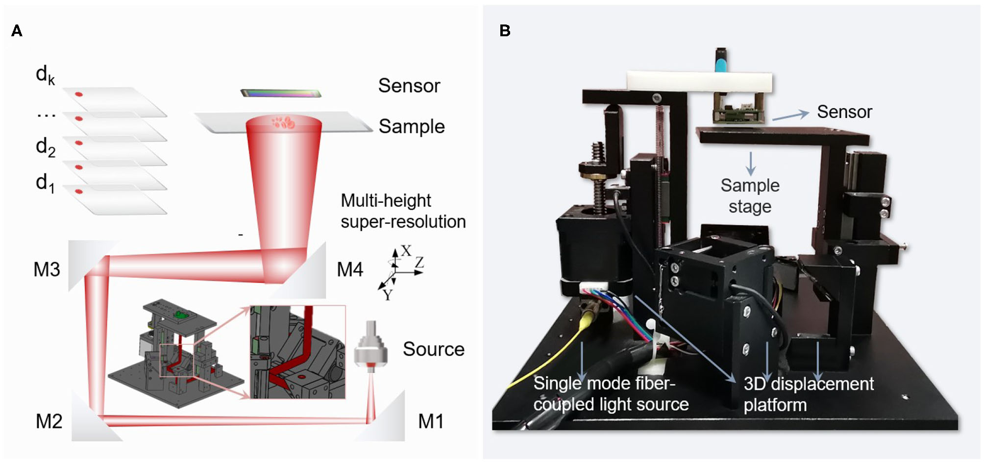
Lensfree system setup based on hardware-driven three-dimensional movement: (A) Schematic diagram of the optical path. (B) Photographs of experimental equipment.
4.2. Amplitude-Contrast Objects
In the first experiment, a standard 2″ × 2″ positive 1951 USAF resolution test target is regarded as amplitude-contrast objects to verify our proposed method. Through the hardware drive setting 10 times in the Z-axis direction, 10 raw holograms at different sample-to-sensor distances can be obtained. The first hologram captured by the camera as shown in Figure 7A. In order to verify that the algorithm automatically focuses on high-frequency information, we mainly analyze the information of the rectangular frame as shown in Figures 7B,C. We will compare the proposed SDIF with three typically existing critical functions, namely DIF, Sobel, SPEC as shown in Figure 7D. It is clearly seen that four methods almost locate the focal plane range of [585, 600] μm. In the focal plane, the critical functions of Sobel and SPEC search for the maximum value of the critical function, while functions DIF and SDIF search for the minimum value of the critical function. However, the critical functions of Sobel, SPEC, and DIF have multiple extremes near the focal plane, which has not a good sensitivity. In high frequency information, reconstruction distance errors of a few microns will directly affect the focusing accuracy. As can be seen in Figures 7B,C, when the reconstruction distance is in the range of [580, 610] μm, the resolution is essentially the same for group 7, However, the reconstruction distance has a large impact on the resolution of groups 8 and 9. Thus, when the resolution is not high, the method described above allows a better focus plane to be determined; but when the resolution is high, especially when pixel super-resolution is performed, the focus distance must be determined accurately. We can see that the SDIF has one of the sharpest valleys, indicating a better sensitivity than the traditional method. Based on the critical function of SDIF, the sequence of reconstructed distances for the different planes can be uniquely determined, as shown in Figure 7E.
Figure 7
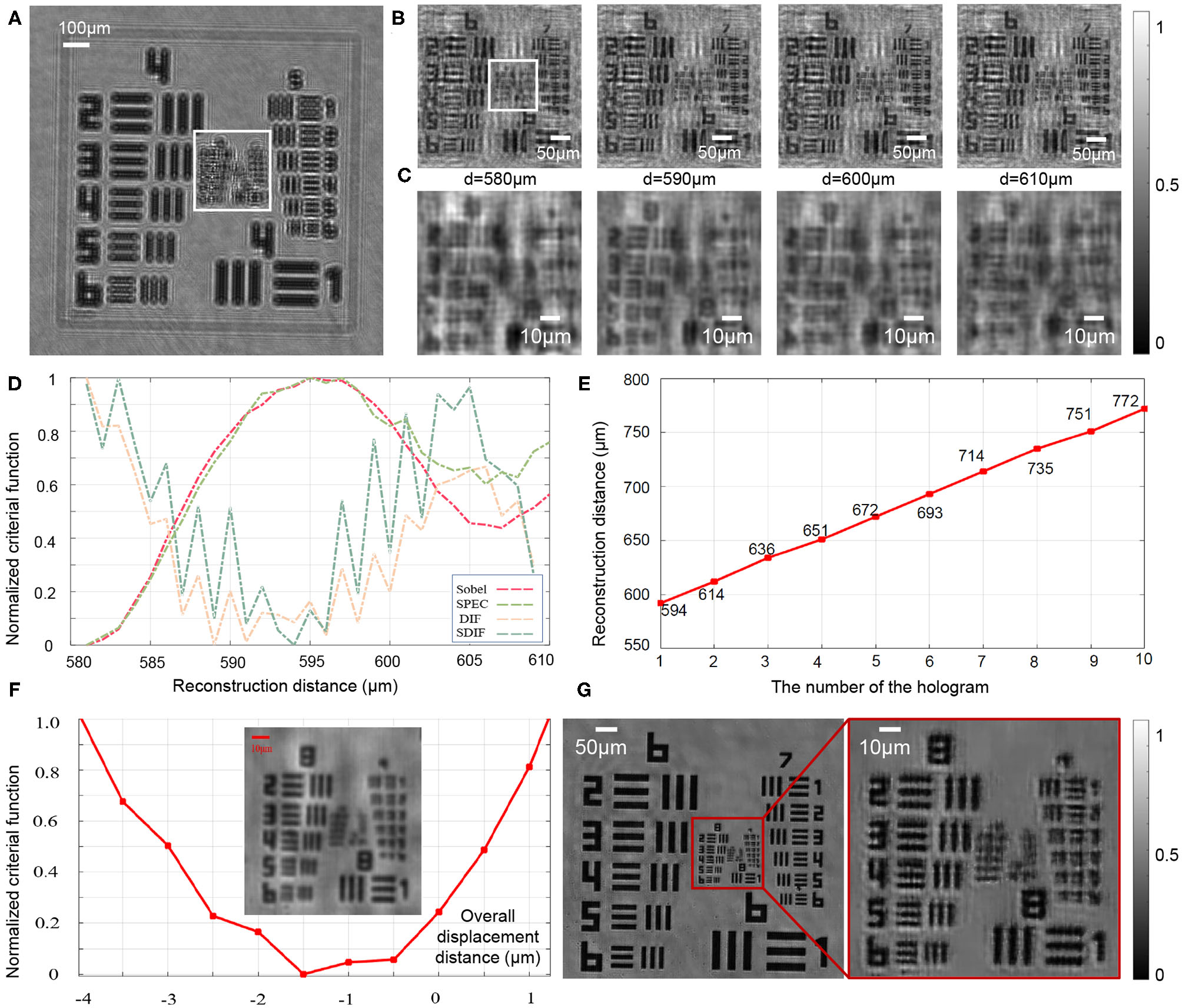
Experimental results for the autofocusing of the amplitude-contrast object. (A) The first hologram captured by the camera. (B) The enlarged region corresponding to the white rectangle area in (A). (C) The enlarged region corresponding to the white rectangle area in (B). (D) The criterion curve of SDIF, DIF, Sobel, SPEC. (E) The reconstruction distance sequences of different planes by SDIF. (F) The synthesized intensity image and the corresponding overall displacement curve. (G) Pixel super-resolution intensity images by APLI.
To determine the reconstructed distances in each plane more accurately, the 10 reconstructed intensity images were transformed into one synthetic intensity image according to Equations (12) and (13), as shown in Figure 7F. It can be clearly seen that the synthesized intensity image has fewer twin-image and clearer detail information. Then, by finding the minimum value of the SDIF critical function, the optimal distance for the overall shift of the reconstructed distance sequence can be determined, as shown in Figure 7F. Therefore, the final reconstruction distance sequence can be determined:D = [594, 614, 636, 651, 672, 693, 714, 735, 751, 772]-1.5 = [592.5, 612.5, 634.5, 649.5, 670.5, 691.5, 712.5, 733.5, 749.5, 770.5] μm. Last, the Figure 7G shows the high-resolution intensity image obtained by the APLI algorithm, which proves the effectiveness of the proposed algorithm.
4.3. Phase-Contrast Objects
In order to evaluate the capability of the proposed method to detect the pure phase object as shown in Figure 8A, we have taken the second experiment. The sample is a benchmark quantitative phase microscopy target, which is completely transparent and can be considered as the phase-contrast sample. The first hologram captured by the camera as shown in Figure 7A. In order to verify that the algorithm automatically focuses on high-frequency information, we mainly analyze the information of the rectangular frame as shown in Figures 8B,C.
Figure 8
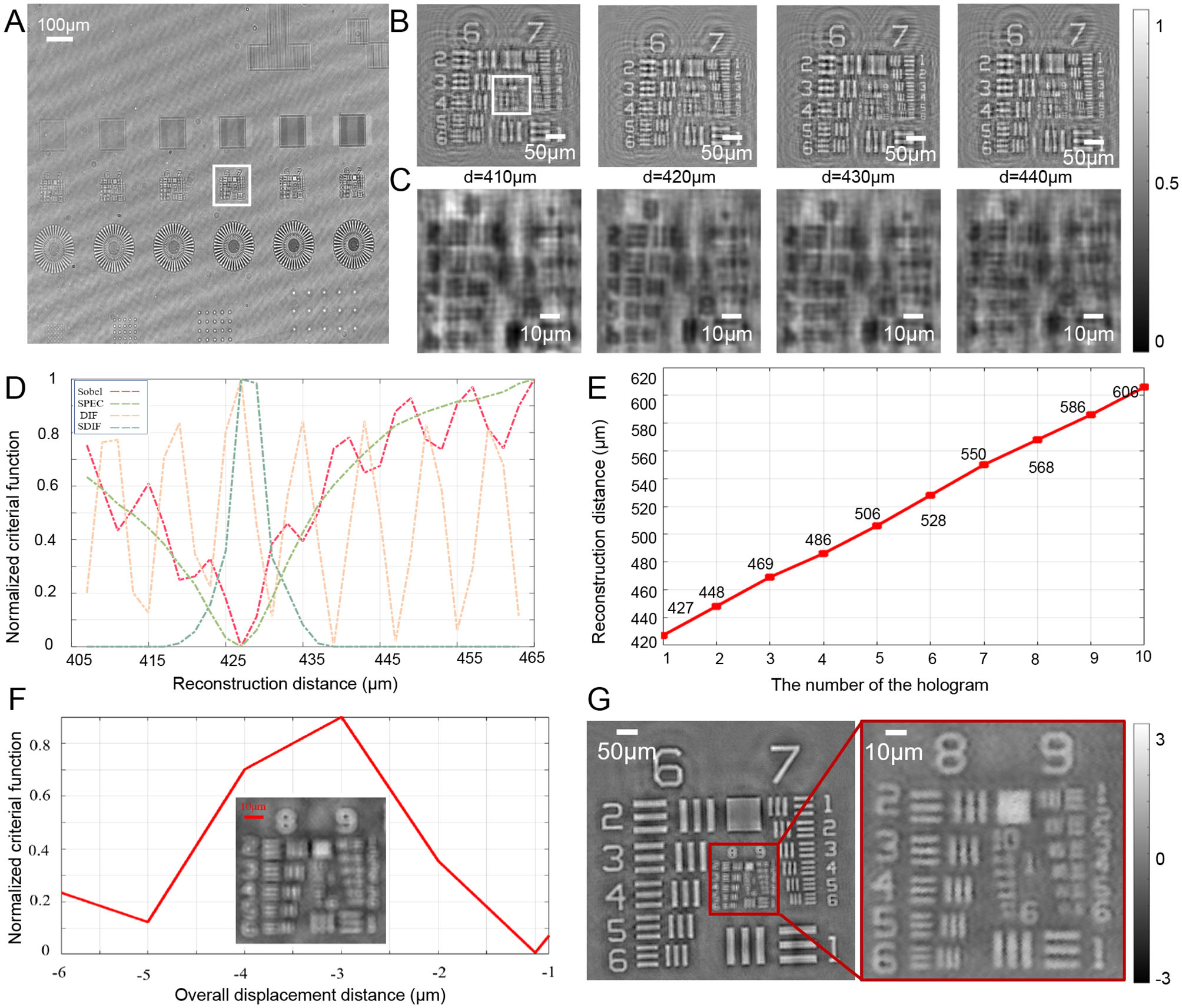
Experimental results for the autofocusing of the phase-contrast object. (A) The first hologram captured by the camera. (B) The enlarged region corresponding to the white rectangle area in (A). (C) The enlarged region corresponding to the white rectangle area in (B). (D) The criterion curve of SDIF, DIF, Sobel, SPEC. (E) The reconstruction distance sequences of different planes by SDIF. (F) The synthesized phase image and the corresponding overall displacement curve. (G) Pixel super-resolution phase images by APLI.
Figure 8D shows the criterion curve of SDIF, DIF, Sobel, and SPEC. It is clearly seen that the critical function of DIF is the form of approximate cosine oscillation, which is difficult to determine the focus position by searching extreme values. The critical functions of Sobel, SPEC, and SDIF could locate the focal plane range of [425, 435] μm by searching the minimum value of the critical functions. For phase-contrast objects, the focus position corresponds to the maximum point of the SDIF critical function. Based on the critical function of SDIF, the initial reconstruction distance sequences of different planes can be uniquely determined [427, 448, 469, 486, 506, 528, 550, 568, 586, 606] μm as shown in Figure 8E. By calculating the maximum value of SDIF for synthesized phase images with a series of overall displacement distance as shown in Figure 8F, the final reconstruction distance sequence can be determined: D = [427, 448, 469, 486, 506, 528, 550, 568, 586, 606]-3 = [424, 445, 466, 483, 503, 525, 547, 565, 583, 603] μm. Last, the Figure 8G shows the high-resolution phase image obtained by the APLI algorithm. It can be clearly seen that the resolution of the phase image has been significantly improved, which proves the effectiveness of the proposed algorithm.
5. Conclusions
In this paper, we present an autofocusing method for multi-height pixel super-resolution lensless on-chip holography. In order to eliminate the influence of twin-image and improve the sensitivity of the critical function, the proposed method is divided into two steps: individual preliminary estimation and global accurate estimation. First, an improved critical function, named SDIF, is proposed to obtain approximate focal distances in different height planes by combining the differential critical function and frequency domain autofocus. To further obtain more accurate reconstructed distance sequences, the intensity or phase images of different heights are synthesized into a high-resolution reference image without twin-image. We transform the focusing problem on different planes into the problem of solving the optimal solution of the whole system, where we consider a series of holograms of different heights as a whole. By shifting the whole of the distance sequence, we can obtain a high-resolution reference image. With the proposed method, we can determine the focal distance at different plane heights more accurately and improve the super-solution accuracy of the imaging. Compared with conventional methods, the proposed method is more sensitive to the accurate reconstruction of distances for high frequency information and is less disturbed by twin-image. Simulations and practical experiments demonstrate the correctness and stability of the proposed algorithm for amplitude-contrast and phase-contrast objects. Considering that the proposed algorithm performs the estimation of individual reconstruction distances and the estimation of overall reconstruction distances, the time spent by the algorithm will increase. In the experiments, the time consumption for 10 images was around 50 s, and how to further reduce computational complexity is the next step of our research.
Statements
Data availability statement
The original contributions presented in the study are included in the article/supplementary material, further inquiries can be directed to the corresponding author/s.
Author contributions
YW conceived the idea. LL and ZL did the experiments. JZ provided Super-resolution algorithm support. CZ supervised the project and provided Technical Support. All the authors contributed to discussion on the results for this manuscript.
Funding
This work was supported by the National Natural Science Foundation of China (61722506, 61905115), Leading Technology of Jiangsu Basic Research Plan (BK20192003), National Defense Science and Technology Foundation of China (2019-JCJQ-JJ-381), Youth Foundation of Jiangsu Province (BK20190445), The Key Research and Development Program of Jiangsu Province (BE2017162), 333 Engineering Research Project of Jiangsu Province (BRA2016407), Fundamental Research Funds for the Central Universities (30920032101, 30920032101), and Open Research Fund of Jiangsu Key Laboratory of Spectral Imaging & Intelligent Sense (3091801410411).
Conflict of interest
The authors declare that the research was conducted in the absence of any commercial or financial relationships that could be construed as a potential conflict of interest.
References
1.
MölderASebestaMGustafssonMGisselsonLWingrenAGAlmK. Non-invasive, label-free cell counting and quantitative analysis of adherent cells using digital holography. J Microsc. (2010) 232:240–7. 10.1111/j.1365-2818.2008.02095.x
2.
ZuoCSunJLiJZhangJAsundiAChenQ. High-resolution transport-of-intensity quantitative phase microscopy with annular illumination. Sci Rep. (2017) 7:1–22. 10.1038/s41598-017-06837-1
3.
ZuoCLiJSunJFanYZhangJLuLet al. Transport of intensity equation: a tutorial. Opt Lasers Eng. (2020) 135:106187. 10.1016/j.optlaseng.2020.106187
4.
WuYChengHWenY. High-precision rotation angle measurement method based on a lensless digital holographic microscope. Appl Opt. (2018) 57:112–8. 10.1364/AO.57.000112
5.
LiJMatlockALiYChenQZuoC. Resolution-enhanced intensity diffraction tomography in high numerical aperture label-free microscopy. Photon Res. (2020) 8:1818. 10.1364/PRJ.403873
6.
BisharaWSuTWCoskunAFOzcanA. Lensfree on-chip microscopy over a wide field-of-view using pixel super-resolution. Opt Exp. (2010) 18:11181–91. 10.1364/OE.18.011181
7.
GreenbaumAZhangYFeiziAChungPLLuoWKandukuriSRet al. Wide-field computational imaging of pathology slides using lens-free on-chip microscopy. Sci Transl Med. (2014) 6:267ra175. 10.1126/scitranslmed.3009850
8.
ZhangJSunJChenQLiJZuoC. Adaptive pixel-super-resolved lensfree in-line digital holography for wide-field on-chip microscopy. Sci Rep. (2017) 7:1–15. 10.1038/s41598-017-11715-x
9.
ZhangJChenQLiJSunJZuoC. Lensfree dynamic super-resolved phase imaging based on active micro-scanning. Opt Lett. (2018) 43:3714–7. 10.1364/OL.43.003714
10.
Garcia-SucerquiaJXuWJerichoMKreuzerHJ. Immersion digital in-line holographic microscopy. Opt Lett. (2006) 31:1211–3. 10.1364/OL.31.001211
11.
ZhangJSunJChenQZuoC. Resolution analysis in a lens-free on-chip digital holographic microscope. IEEE Trans Comput Imaging. (2020) 6:697–710. 10.1109/TCI.2020.2964247
12.
LuoWZhangYGöröcsZFeiziAOzcanA. Propagation phasor approach for holographic image reconstruction. Sci Rep. (2016) 6:22738. 10.1038/srep22738
13.
LuoWGreenbaumAZhangYOzcanA. Synthetic aperture-based on-chip microscopy. Light: Sci Appl. (2015) 4:e261. 10.1038/lsa.2015.34
14.
BisharaWSikoraUMudanyaliOSuTWYaglidereOLuckhartSet al. Holographic pixel super-resolution in portable lensless on-chip microscopy using a fiber-optic array. Lab Chip. (2011) 11:1276–9. 10.1039/c0lc00684j
15.
GohshiSHiroiTEchizenI. Subjective assessment of HDTV with superresolution function. EURASIP J Image Video Process. (2014) 2014:11. 10.1186/1687-5281-2014-11
16.
HardieRCBarnardKJArmstrongEE. Joint MAP registration and high-resolution image estimation using a sequence of undersampled images. IEEE Trans Image Process. (1997) 6:1621–33. 10.1109/83.650116
17.
WoodsNAGalatsanosNPKatsaggelosAK. Stochastic methods for joint registration, restoration, and interpolation of multiple undersampled images. IEEE Trans Image Process. (2005) 15:201–13. 10.1109/TIP.2005.860355
18.
ZhengGLeeSAYangSYangC. Sub-pixel resolving optofluidic microscope for on-chip cell imaging. Lab Chip. (2010) 10:3125–9. 10.1039/c0lc00213e
19.
CoskunAFNagiRSadeghiKPhillipsSOzcanA. Albumin testing in urine using a smart-phone. Lab Chip. (2013) 13:4231–8. 10.1039/c3lc50785h
20.
LuoWZhangYFeiziAGöröcsZOzcanA. Pixel super-resolution using wavelength scanning. Light Sci Appl. (2016) 5:e16060. 10.1038/lsa.2016.60
21.
GaoPYaoBRuppRMinJGuoRMaBet al. Autofocusing based on wavelength dependence of diffraction in two-wavelength digital holographic microscopy. Opt Lett. (2012) 37:1172–4. 10.1364/OL.37.001172
22.
WenYWangHAnandAQuWChengHDongZet al. A fast autofocus method based on virtual differential optical path in digital holography: theory and applications. Opt Lasers Eng. (2019) 121:133–42. 10.1016/j.optlaseng.2019.04.006
23.
LyuMYuanCLiDSituG. Fast autofocusing in digital holography using the magnitude differential. Appl Opt. (2017) 56:F152–7. 10.1364/AO.56.00F152
24.
IlhanHADoǧarMÖzcanM. Fast autofocusing in digital holography using scaled holograms. Opt Commun. (2013) 287:81–4. 10.1016/j.optcom.2012.09.036
25.
YuLCaiL. Iterative algorithm with a constraint condition for numerical reconstruction of a three-dimensional object from its hologram. JOSA A. (2001) 18:1033–45. 10.1364/JOSAA.18.001033
26.
DuboisFSchockaertCCallensNYourassowskyC. Focus plane detection criteria in digital holography microscopy by amplitude analysis. Opt Exp. (2006) 14:5895–908. 10.1364/OE.14.005895
27.
LangehanenbergPKemperBDirksenDVon BallyG. Autofocusing in digital holographic phase contrast microscopy on pure phase objects for live cell imaging. Appl Opt. (2008) 47:D176–82. 10.1364/AO.47.00D176
28.
GillespieJKingRA. The use of self-entropy as a focus measure in digital holography. Pattern Recogn Lett. (1989) 9:19–25. 10.1016/0167-8655(89)90024-X
29.
LiWLoomisNCHuQDavisCS. Focus detection from digital in-line holograms based on spectral l 1 norms. JOSA A. (2007) 24:3054–62. 10.1364/JOSAA.24.003054
30.
MemmoloPPaturzoMJavidiBNettiPAFerraroP. Refocusing criterion via sparsity measurements in digital holography. Opt Lett. (2014) 39:4719–22. 10.1364/OL.39.004719
31.
YangYKangBsChooYj. Application of the correlation coefficient method for determination of the focal plane to digital particle holography. Appl Opt. (2008) 47:817–24. 10.1364/AO.47.000817
32.
TianJMaKK. Stochastic super-resolution image reconstruction. J Vis Commun Image Represent. (2010) 21:232–44. 10.1016/j.jvcir.2010.01.001
33.
RihaLFischerJSmidRDocekalA. New interpolation methods for image-based sub-pixel displacement measurement based on correlation. In: 2007 IEEE Instrumentation &Measurement Technology Conference IMTC 2007, Warsaw: Instrumentation & Measurement Magazine IEEE. (2007). p. 1–5. 10.1109/IMTC.2007.379183
34.
ParkSCParkMKKangMG. Super-resolution image reconstruction: a technical overview. IEEE Signal Process Mag. (2003) 20:21–36. 10.1109/MSP.2003.1203207
Summary
Keywords
lensfree on-chip imaging, autofocusing, super-resolution, phase retrieval, computational imaging
Citation
Wu Y, Lu L, Zhang J, Li Z and Zuo C (2021) Autofocusing Algorithm for Pixel-Super-Resolved Lensfree On-Chip Microscopy. Front. Phys. 9:651316. doi: 10.3389/fphy.2021.651316
Received
09 January 2021
Accepted
03 March 2021
Published
29 March 2021
Volume
9 - 2021
Edited by
Peng Gao, Xidian University, China
Reviewed by
Shaohui Zhang, Beijing Institute of Technology, China; Lihong Ma, Zhejiang Normal University, China
Updates
Copyright
© 2021 Wu, Lu, Zhang, Li and Zuo.
This is an open-access article distributed under the terms of the Creative Commons Attribution License (CC BY). The use, distribution or reproduction in other forums is permitted, provided the original author(s) and the copyright owner(s) are credited and that the original publication in this journal is cited, in accordance with accepted academic practice. No use, distribution or reproduction is permitted which does not comply with these terms.
*Correspondence: Chao Zuo zuochao@njust.edu.cn
This article was submitted to Optics and Photonics, a section of the journal Frontiers in Physics
Disclaimer
All claims expressed in this article are solely those of the authors and do not necessarily represent those of their affiliated organizations, or those of the publisher, the editors and the reviewers. Any product that may be evaluated in this article or claim that may be made by its manufacturer is not guaranteed or endorsed by the publisher.