 Haibo Wang
 Zaichen Zhang*
 Yidi Zhang
- National Mobile Communications Research Laboratory, Southeast University, Nanjing, China
This paper proposes a free space optical communication (FSO) receivier system with adaptive alignment based on pure phase holographic imaging. During the frame header transmission period, the optical phased array in this system performs specific holographic imaging on the receiving plane, which assist the system to undergo beam alignment. The system model has been built in this work, along with the receiving signal expression. Based on the physical model, we propose an algorithm for positioning calibration and the circuitous phased encoding for improvement of imaging quality and algorithm complexity.
1. Introduction
With the increasing demand for spectrum resources, optical communication has become an indispensable part of future communication systems. Traditional optical communication is mainly oriented to long-distance transmission scenarios for point-to-point users, and relies on the direct link [1–4]. Therefore, its receiver does not require high beam alignment, which is only limited to the correction of natural jitter. However, with the introduction of concepts, such as optical mobile communications and intelligent reflecting surfaces, many studies have tried to apply optical communications to mobile multi-user scenarios [5–9]. This directly leads to an increasing demand for receiver alignment accuracy. Therefore, an optical receiver that can be adaptively aligned is very important for the development of optical communications. In Kiasaleh [10], performance of the proposed optimum receiver is assessed in terms of the overall bit error rate. In Zhou et al. [11], a novel scheme of adaptive dispersion equalization, which supports parallel processing, is proposed. Kobayashi et al. [12] develop a 2.5 Gb/s optical receiver with an adaptive decision threshold detection scheme. In Mai and Kim [13], two adaptive beam control techniques have been studied and the author built an alignment system on both the receiving end and the transmitting end, which further improves the alignment accuracy. Although there are many FSO adaptively calibrated receivers in the existing work, most of them require a feedback link between the transmitter and the receiver and are based on a mechanical structure, which has low accuracy and is easy to tear. Our optical phase control array (OPA) adjustment method based on the pure phase holographic imaging, its complexity mainly depends on the imaging holographic conversion algorithm, whose liquid crystal cell is very stable. In addition, the entire receiver can remain macroscopically static and its weight is very small.
In He et al. [14], wave front sensor-less adaptive optics (AO) technology is used to compensate wave front distortions caused by atmospheric turbulences. A hybrid method by a suitable combination of stochastic parallel gradient descent (SPGD) algorithm has been propsed. For FSO systems, whether it is a fading compensation algorithm or a calibration algorithm, the complexity of the algorithm seriously affects the performance of the system. Therefore, people are constantly optimizing the algorithm in the system to increase the computing speed [15–17]. In this work, we use circuitous phased encoding for accurate alignment to reduce the complexity of image and hologram conversion, which further increases the calculation speed and reduces handling delays.
This paper presents a free space optical communication (FSO) receiver with adaptive alignment based on pure phase holographic imaging. The receiver system consists of a traditional FSO receiver, an optical phased array and optical components. In the transmission stage of the frame header, the OPA utilizes holographic projection to jointly determine the relative position of the optical beam and the receiver, thus making corresponding adjustments. After that, the information part of the optical signal is directly transmitted to the calibrated receiver. The contributions of this work are as follows:
• This paper designs an optical receiver that can be self-adaptively aligned. Compared with the existing adaptive optical receiver controlled by mechanical steering gear, its signal receiving process is divided into two stages, namely, the optical signal irradiating on the OPA and the OPA aligning the signal to the center of the receiver.
• This system uses the holographic imaging technology of the optical phased array to assist positioning. In the frame header transmission stage of the optical signal, the OPA illuminates a specific pattern to the receiver. The spatial distribution of the light amplitude of the pattern is uneven, and the light intensity of different coordinates is different. Therefore, the receiver can determine the relative position between itself and the optical signal according to the received optical power, and feed it back to the OPA. OPA makes fine adjustments based on the feedback information to align the center of the beam with the center of the receiver. Compared with the method using multiple light sources for positioning, this solution does not require redundant signal transmission at the transmitting end. At the same time, the system does not need to add a new feedback link at the transmitter and receiver, thereby reducing the complexity of the system.
The rest of this paper is organized as follows: In section 2, we propose the model of the system. The receiving signal and the corresponding channel fading are analyzed. In section 3, an algorithm for positioning calibration with OPA is proposed. In section 4, The circuitous phased encoding is utilized in the system for improving the quality of the recovered light field and decreasing the algorithm complexity. Section 6 draws conclusion.
2. System Model
2.1. Overview of the Adaptive Receiver System
As shown in Figure 1, the receiver system consists of a transmissive OPA, lens system and optical receiver (photodiode or coherent receiver). The base station directly transmits the optical signal to the OPA. The OPA adjust the beam for aiming at the center of the receiver. The optical signal contains the frame header and the data part, as shown in Figure 2. The data frame header can be an unmodulated uniform light field, which is used to generate a specific pattern with OPA. The light intensity of this pattern obeys a specific distribution to ensure that the light intensity received by the receiver at different positions is completely different. Therefore, the receiver can feed back its location to the OPA according to the received light intensity. Before analyzing the specific control method of the system, we need to model the signal received by the receiver.
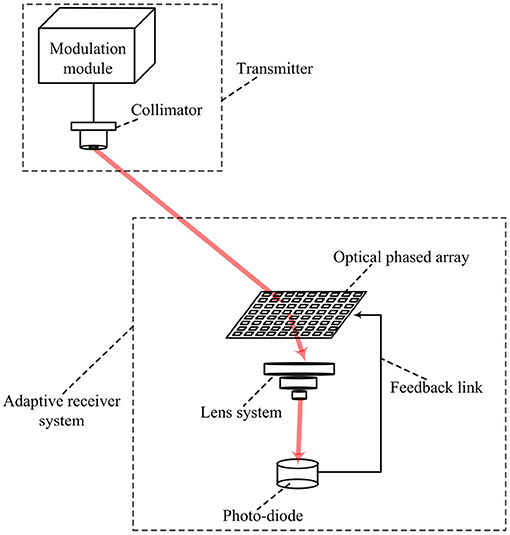
Figure 1. Structure of FSO receiver system with adaptive alignment.
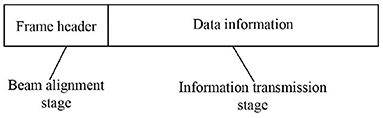
Figure 2. Construction of data frame.
2.2. Receiving Signal and Channel Modeling
We utilize intensity-modulation/direct detection (IM/DD) with on-off keying (OOK) modulation in this system. The receiving signal can be presented as
where n denotes the Gaussian noise with variance of and mean of zero; is the transmit intensity for x = 1; h is the channel fading, where
where Gt, Gr, Lp, La, ha, hp are the transmitting optics gain, receiving gain, propagation loss, atmospherical power loss, the turbulence-induced intensity fading, the pointing error-induced intensity fading, respectively [1, 2, 18]. We can have , where θb is the diffraction-limited beam angle; , where A is the normal receving area and λ is the wavelength; , where d is the distance from the transmitter and receiver; , where σp is the extinction loss coefficient of the channel in reciprocal distance units. hp is the channel fading caused by the deviation of the beam center from the receiver center, which can be reduced by adaptive adjustment of the receiver. Since hp is one of the most important factors affecting the performance of the receiving signal, the alignment of the optical signal is meaningful for the communication system.
Then the channel fading can be expressed as
where are constants, ha, hp are random variables that affecting the system's small-scale fading.
3. Adaptive Alignment With Optical Phased Array
The device for both optical imaging and fine-tuning in this system is the OPA. Therefore, OPA is the core of the system and we need to design its adjustment method. Figure 3 shows the structure of the OPA. We assume that there are M × N phased units in OPA. Each unit can be regarded as a square with the side length of d. The spacing between units is δd. The amplitude function of the light field through the OPA t(x, y) is
where i(x, y) is the light field irradiated on the OPA, rect(.) is the rectangular function, ⊗ is the convolution operation, a(x, y), q(x, y), and p(x, y) are
where φ is the phase shift superimposed on the OPA unit, φc is the phase shift superposed on the gaps between OPA units. Since the light field modulated by OPA needs to pass through a lens group to restore the desired light field, the light field needs to undergo optical Fourier transform. The reconstructed light field amplitude distribution function T(u, v) is the Fourier transform of the original OPA's reflectivity function t(x, y), that is T(u, v) = F{t(x, y)}, where F{} is the Fourier transform. Incorporating (4), we can obtain
where
The OPA control signal is the φ on each phased unit. According to the (8), when we determine the desired light field T(u, v), we can inversely deduce the OPA reflectivity function t(x, y), thereby determining the phase distribution of units φ on the OPA. Therefore, whether it is to perform holographic projection at the frame head or adjust the position of the beam in the frame header stage, we only need to edit T(u, v) and substitue it into (8). Assume that the receiving area of the photodiode is S. In the stage of frame header transmission, the holographic imaging we design needs to cover the maximum range of OPA beam deflection. Moreover, the design of the holographic imaging needs to ensure that when the center of the diode is at different coordinates, the light intensity on the area S is different. Thus, we can confirm the coordinates of the receiver center in the OPA projection plane according to the feedback path of the photodiode. In the data transmission stage, we can set T(u, v) as a tiny spot at the center coordinates of the receiver. However, the Fourier holographic algorithm of this scheme has high computational complexity and low imaging quality. Therefore, in this system, we should use circuitous phased encoding to improve imaging quality and reduce algorithm complexity.
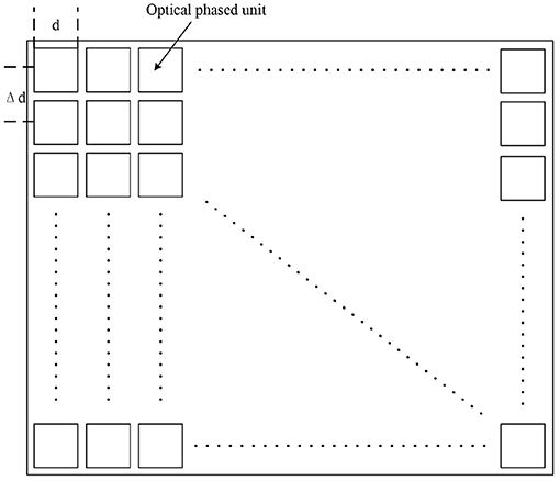
Figure 3. Structure of the optical phased array.
4. Circuitous Phased Encoding for Accurate Alignment
Encoding is to convert the complex amplitude distribution of the sampled image into the transmittance function of the computed hologram, so that it can improve imaging quality and reduce algorithm complexity.
Suppose we want to encode a complex function
where F(u) represents the phase distribution function of the spatial frequency u. M(u) represents the amplitude information we want to encode. Assuming that the optical field transfer function is a pure phase function, since the approximate power loss in free space is 0. Then the expected optical field function is
In order to restore the image through the lens, we need to encode the transfer function in the form of Fourier series, namely
In the above formula, the coefficient is
The n-order expansion in the function formula can be interpreted as forming different diffraction orders. So this function not only encodes the phase distribution, but also encodes the amplitude information within the coefficients. Among them, n = 0 and n = 1 are the two most important levels. The first diffraction order (n = 1) reproduces the original phase function F(u), and is amplitude modulated according to it. Then we can reproduce any desired complex transfer function with the first diffraction order. However, due to the sinc function in, the amplitude function M(u) will be distorted to a certain extent. To solve it, we will multiply the complex conjugate of the exponential factor, i.e., keep the sinc function part, and obtain
Then we compensate for the distortion generated by the sinc function, construct a distortion compensation look-up table, and build the distortion modulation function accordingly. In the end we can get an ideal distortion-free function, namely
Compared with the Fourier holography reconstruction before the improvement, the holographic imaging under this encoding method has higher quality of the recovered light field and lower algorithm complexity.
5. Experimental Results
Since the beam deflection angle of OPA is small and it is difficult to perform large-scale beam scanning with OPA alone, we can only use it to assist in improving the tracking accuracy when there exists a beam tracking system at the transmitter. Therefore, the OPA-controlled FSO adaptive calibration receiver proposed in this paper is only suitable for real-time high-precision calibration when the beam deviates from the center of the receiver in a small range. When the user moves, we still need to place the mechanical calibration structure on the transmitter to track the user. Figure 4 is an experimental photo of OPA assisted tracking. The left is the mechanical tracking system at the transmitter and the right is FSO receiver with adaptive alignment based on pure phased holographic imaging. The experimental measurement data of the system's handing delay is shown in Table 1.
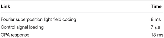
Table 1. Handing delays.
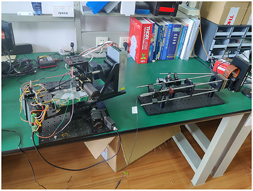
Figure 4. Experiment of OIRS assisted tracking.
6. Conclusion
This paper proposes a FSO receivier system with adaptive alignment based on pure phase holographic imaging. Compared with the traditional receiver, this scheme is equivalent to increasing the receiving area, since the area of OPA is much larger than that of the receiver. In addition, this system is also one of the solutions for target tracking in optical mobile communication. Each time a data frame is transmitted, the receiver system will perform a signal alignment, which transfers parts of the burden for signal tracking to the receiving end.
Data Availability Statement
The original contributions presented in the study are included in the article/supplementary material, further inquiries can be directed to the corresponding author/s.
Author Contributions
In this work, HW was responsible for writing the paper. ZZ was responsible for the design of the system and experiment. YZ was responsible for building the experimental platform and conducting experiments. All authors contributed to the article and approved the submitted version.
Funding
This work was supported by NSFC projects (61960206005, 61971136, 61803211, and 61871111), Jiangsu NSF project (BK20191261), Zhejiang Lab (No. 2019LC0AB02), the Fundamental Research Funds for the Central Universities, and Research Fund of National Mobile Communications Research Laboratory, Southeast University.
Conflict of Interest
The authors declare that the research was conducted in the absence of any commercial or financial relationships that could be construed as a potential conflict of interest.
References
1. Khalighi MA, Uysal M. Survey on free space optical communication: a communication theory perspective. IEEE Commun Surv Tutor. (2014) 16:2231–58. doi: 10.1109/COMST.2014.2329501
2. Navidpour SM, Uysal M, Kavehrad M. BER performance of free-space optical transmission with spatial diversity. IEEE Trans Wireless Commun. (2007) 6:2813–9. doi: 10.1109/TWC.2007.06109
3. Kaushal H, Kaddoum G. Optical communication in space: challenges and mitigation techniques. IEEE Commun Surv Tutor. (2017) 19:57–96. doi: 10.1109/COMST.2016.2603518
4. Ansari IS Yilmaz F Alouini M. Performance analysis of free-space optical links over Málaga () turbulence channels with pointing errors. IEEE Trans Wireless Commun. (2016) 15:91–102. doi: 10.1109/TWC.2015.2467386
5. Zhang Z, Wu L, Dang J, Zhu G, Hu J, Jiang H, et al. Optical mobile communications: principles and challenges. In: 2017 26th Wireless and Optical Communication Conference (WOCC). Newark, NJ (2017). p. 1–4. doi: 10.1109/WOCC.2017.7928992
6. Zhang Z, Dang J, Wu L, Wang H, Xia J, Lei W, et al. Optical mobile communications: principles, implementation, and performance analysis. IEEE Trans Vehic Technol. (2019) 68:471–82. doi: 10.1109/TVT.2018.2880817
7. Najafi M, Schober R. Intelligent reflecting surfaces for free space optical communications. In: 2019 IEEE Global Communications Conference (GLOBECOM). Waikoloa, HI (2019). p. 1–7. doi: 10.1109/GLOBECOM38437.2019.9013840
8. Yang Y, Zheng B, Zhang S, Zhang R. Intelligent reflecting surface meets OFDM: protocol design and rate maximization. IEEE Trans Commun. (2020) 68:4522–35. doi: 10.1109/TCOMM.2020.2981458
9. Yuan J, Liang YC, Joung J, Feng G, Larsson EG. Intelligent reflecting surface-assisted cognitive radio system. IEEE Trans Commun. (2020) 69:675–87. doi: 10.1109/TCOMM.2020.3033006
10. Kiasaleh K. Receiver architecture for channel-aided, OOK, APD-based FSO communications through turbulent atmosphere. IEEE Trans Commun. (2015) 63:186–94. doi: 10.1109/TCOMM.2014.2367000
11. Zhou X, Chen X, Zhu H, Zhou W, Fan Y. Parellel implementation of adaptive equalization for high-speed and real-time optical coherent receivers. In: The 19th Annual Wireless and Optical Communications Conference (WOCC 2010). Shanghai (2010). p. 1–5. doi: 10.1109/WOCC.2010.5510671
12. Kobayashi I, Shiraiwa M, Maekawa T, Inami D, Kuriyama T. Compact optical receiver with adaptive decision threshold detection for multi-gigabit terrestrial DWDM transmission systems. In: 2002 28TH European Conference on Optical Communication. Vol. 4. Copenhagen (2002). p. 1–2.
13. Mai VV, Kim H. Adaptive beam control techniques for airborne free-space optical communication systems. Appl Opt. (2018) 57:7462–71. doi: 10.1364/AO.57.007462
14. He X, Zhao X, Cui S, Gu H. A rapid hybrid wave front correction algorithm for sensor-less adaptive optics in free space optical communication. Opt Commun. (2018) 429:127–37. doi: 10.1016/j.optcom.2018.08.008
15. Piscaer P, Soloviev O, Verhaegen M. Predictive wavefront sensorless adaptive optics for time-varying aberrations. J Opt Soc Am A. (2019) 36:1810–9. doi: 10.1364/JOSAA.36.001810
16. Gu H, Liu M, Liu H, Yang X, Liu W. An algorithm combining convolutional neural networks with SPGD for SLAO in FSOC. Opt Commun. (2020) 475:126243. doi: 10.1016/j.optcom.2020.126243
17. Ke CN X. Experimental research on phase diversity method for correcting vortex beam distortion wavefront. Appl Phys B. (2020) 126:66. doi: 10.1007/s00340-020-7413-7
Keywords: adaptive optical receiver, free space optical communication, holographic imaging, circuitous phased encoding, positioning calibration
Citation: Wang H, Zhang Z and Zhang Y (2021) FSO Receiver With Adaptive Alignment Based on Pure Phased Holographic Imaging. Front. Phys. 9:661843. doi: 10.3389/fphy.2021.661843
Received: 31 January 2021; Accepted: 26 March 2021;
Published: 21 April 2021.
Edited by:
Gang Zhang, Nanjing Normal University, ChinaReviewed by:
Mukun He, Tsinghua University, ChinaPeter R. Hobson, Queen Mary University of London, United Kingdom
Jingyuan Zheng, Tsinghua University, China
Copyright © 2021 Wang, Zhang and Zhang. This is an open-access article distributed under the terms of the Creative Commons Attribution License (CC BY). The use, distribution or reproduction in other forums is permitted, provided the original author(s) and the copyright owner(s) are credited and that the original publication in this journal is cited, in accordance with accepted academic practice. No use, distribution or reproduction is permitted which does not comply with these terms.
*Correspondence: Zaichen Zhang, emN6aGFuZ0BzZXUuZWR1LmNu