 Hao Zhang
 Tong Sun
 Shi-Wei Hou1*
- 1School of Civil Engineering, Shenyang Jianzhu University, Shenyang, China
- 2Academy of Science and Technology, Shenyang Jianzhu University, Shenyang, China
The effect of aftershocks on the fragility of single-story masonry structures is investigated using probabilistic seismic demand analysis Finite element models of an unreinforced masonry (URM) structure and a confined masonry (CM) structure are established and their seismic response characteristics when subjected to mainshock, aftershock, and the mainshock-aftershock sequence are then comparatively investigated. The effects of aftershocks and the use of confining members on the seismic response are studied. Probabilistic seismic demand models of the structures are built, and fragility curves under various conditions are derived to investigate the effect of aftershocks on structural fragility. The maximum roof displacement and maximum inter-story drift ratio are lower in the confined masonry model than in the unreinforced masonry model; additionally, the probability of exceedance (PE) values of each damage limit state reduced, and those of the mainshock-damaged models subjected to aftershock significantly increase compared to those directly subjected to a same-intensity aftershock. The probability of severe damage or collapse compared with the mainshock-damaged CM model is greater than when each is subjected to a same intensity aftershock. The use of confining members benefits aftershock resistance and reduces the failure probability of the mainshock-damaged structure. The PE values significantly increase with the aftershock scaling factor δ. Therefore, the effect of aftershocks should be considered in the seismic design and analysis of masonry structures.
Introduction
Strong earthquakes are often accompanied by aftershocks, and large numbers of aftershocks have been recorded in multiple earthquakes [1–4]. In 1999, a magnitude 7.4 earthquake occurred in Izmit, Turkey, followed by a magnitude 5.9 aftershock within a month after the earthquake, resulting in the collapse of some mainshock-damaged structures that did not collapse during the mainshock [5]. In 2002, an earthquake of magnitude 5.4 hit Molize, Italy, and several RC frame structures with only minor damage from the mainshock were severely damaged by aftershocks [6]. An earthquake of magnitude 8.0 occurred in 2008 in Wenchuan, China, after which more than 28,000 aftershocks were recorded, several exceeding magnitude 5.0 [7]. A magnitude 9.0 earthquake hit Japan in 2011, and over 1,000 aftershock ground motions were recorded, including four aftershocks with magnitudes exceeding 7.0 [8]. In 2015, an earthquake of magnitude 7.8 in west-central Nepal caused enormous casualties and property loss in the region from the strong mainshock and multiple subsequent aftershocks [9]. The mainshock may cause various degrees of plastic damage to structures, which can be further aggravated by aftershocks, along with an accordant change in the dynamic characteristics of the structures. The time interval between the occurrence of the mainshock and aftershocks is generally short; hence, unless repaired in time, mainshock-damaged structures may be severely damaged or even collapse under even a low-intensity aftershock [10–12]. In recent years, research on the effects of aftershocks on the seismic performance of structures has garnered great attention. Goda and Taylor [13] investigated the nonlinear response of structures under mainshock-aftershock sequences using single-degree-of-freedom (SDOF) systems, and their results revealed that aftershocks significantly affect the peak ductility demand of structures. Hosseinpour and Abdelnaby [14] studied the effects of various aspects of the mainshock and aftershocks, such as their input directions and vertical components, on the seismic performance of RC structures and showed that the input direction of aftershocks has a significant effect on the displacement demand of irregular structures. Wang et al. [15] investigated the seismic fragility of a continuous girder bridge subjected to a mainshock-aftershock sequence. It was concluded that the aftershock increases the seismic demand and failure probability of the structure and that a structure that reaches a moderate damage state after the mainshock is at the highest risk of damage when subjected to an aftershock. Zhang et al. [16] investigated the seismic fragility of concrete-filled steel tubular frame structures under earthquake sequences based on nonlinear seismic response analysis and probabilistic seismic demand analysis (PSDA); the results showed that the failure probabilities of structures in various damage limit states under earthquake sequences all increase compared to those subjected to mainshocks only. Salami et al. [17] investigated the seismic fragility of low-rize RC structures under mainshock-aftershock sequences using incremental dynamic analysis based on the OpenSees software platform. It was demonstrated that the probability of severe damage or the collapse of structures increases significantly if the aftershock effect was considered. Pang et al. [18] carried out nonlinear response analysis of a high concrete-face rockfill dam subjected to the selected as-recorded mainshock–aftershock sequences and investigated the effects of aftershocks on the seismic fragility of the dam, showing that aftershocks increase the probability of exceedance (PE) of various damage limit states of the dam. Zhao et al. [19] studied the influence of aftershocks on the seismic fragility of nuclear power plants, the results showed that aftershocks cause additional damage to the structure, leading to a significant increase in the PE values of different damage limit states. Han et al. [20] conducted seismic loss estimation of structures using RC frame buildings as a case study and the recorded mainshock-aftershock sequences as the ground motion input. It was concluded that aftershocks increase economic losses and casualties and, to some extent, structural repair costs. Nazari et al. [21] examined the effect of aftershocks on the seismic fragility of wood structures and suggested that their effect be reasonably considered in performance-based seismic design.
Masonry structures are extensively used in rural areas of China due to their low cost and simple construction. However, this type of structure has certain disadvantages such as large self-weight and low tensile and shear strengths of materials, etc. There is a lack of standard design and quality control procedures, leading to poor seismic performance of these structures [22], which are highly susceptible to severe damage or even collapse under strong earthquake shaking. Seismic experience data after the 2008 Wenchuan earthquake discovered that masonry structures suffered the most severe damage and accounted for the largest number of collapses, causing the largest property loss and number of casualties [23]. Bessason et al. [24] developed seismic fragility models for different types of structures using statistical methods and based on earthquake experience data. The results showed that the damage limit state probabilities of masonry structures are higher than those of RC and wood structures. Biglari and Formisano [25] established empirical fragility curves of masonry structures in Sarpol-e-zahab and Bam, Iran, using the RISK-UE level 1 method and based on damage data from post-earthquake reconnaissance in this region. Del Gaudio et al. [26] investigated the main parameters influencing structural damage and proposed a method for assessing the seismic fragility of masonry structures based on the post-earthquake structural damage data. Saloustros et al. [27] proposed a method for seismic fragility assessment considering the uncertainty in material parameters and used the method to study the seismic fragility of historical masonry structures.
Currently, most studies on masonry structures focus on quasistatic tests of their structural members or shaking-table tests and numerical simulation analyses that mostly consider single earthquake shaking [28–30]. As stated above, there is a relative lack of research on the fragility of masonry structures and their susceptibility to aftershocks, leaving room for improvement in the seismic design and seismic risk assessment methods of masonry structures. In particular, masonry structures in rural areas are typically not designed properly, and many self-built houses lack the necessary confining members, so these masonry structures have poor seismic performance. To address this problem, taking a typical single-story masonry structure of the rural areas of Northeast China as an example, the present study builds finite element models of unreinforced masonry (URM) structure and confined masonry (CM) structural models, investigates the seismic responses and fragility of masonry structures subjected to mainshock, aftershock and mainshock-aftershock sequence using nonlinear dynamic time history analysis and PSDA, and comparatively analyzes the effects of confining members such as ring beams and confined boundary columns on the seismic response and fragility of masonry structures. On this basis, the effect of aftershocks on the seismic response and fragility of mainshock-damaged masonry structures is investigated in depth, and the effects of confining members and the aftershock scaling factor are also examined.
The Description of Structural Models
Finite Element Models of Masonry Structures
As shown in Figure 1, the single-story masonry structure studied herein has a plan dimension of 11.5 × 7.9 m, a story height of 3 m, and a roof height of 5.4 m. The masonry wall is built with MU10 bricks and M2.5 mortar. It has a density of 2000 kg/m³, a Poisson’s ratio of 0.15, and an elastic modulus of 1.827 × 10⁹ N/m2. The ring beams and the confined boundary column are made of C20 concrete, which has a cubic compressive strength of 20 MPa, a density of 2,500 kg/m3, and a Poisson’s ratio of 0.2. The reinforcing bars in confining members are made of HPB300 steel, which has a yield strength of 300 MPa, a density of 7,800 kg/m³, a Poisson’s ratio of 0.3, and an elastic modulus of 2.1 × 10¹¹ N/m2. Finite element models of URM and CM structures were established with ABAQUS software, as shown in Figure 2. Masonry walls were simulated by shell elements, and ring beams and confined columns were simulated by fiber beam elements. A modal analysis [31] was conducted to obtain the fundamental periods of the URM and CM models: TURM-1 = 0.114 s and TCM-1 = 0.107 s.
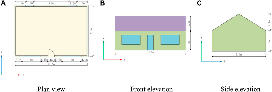
FIGURE 1. Detail dimensions and layout of the single-story masonry structures. (A) Plan view. (B) Front elevation. (C) Side elevation.
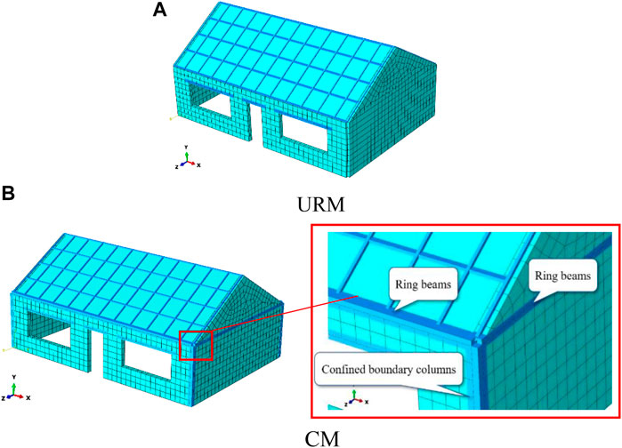
FIGURE 2. Finite element models of single-story masonry structures. (A) URM. (B) CM.
Constitutive Model of Masonry Material
Compressive Stress-Strain Relationship of Masonry Material
The compressive stress-strain relationship of masonry suggested in reference [32] was adopted in the present study, as shown in Figure 3A. The corresponding stress-strain curve includes a parabolic ascending branch and a linear descending branch. The ascending branch is expressed as follows:
Where σc is the compressive stress, εc is the compressive strain, fc′ is the peak compressive stress, εc’ is the compressive strain corresponding to fc′, fb is the compressive strength of block, fj is the compressive strength of mortar, and Ec is the elastic modulus of masonry. Cj is determined by the mortar strength. The linear descending branch is determined by the points {εc@0.9fc’, 0.9 fc’} and {2.75εc′, 0.2 fc′}.
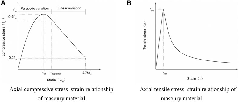
FIGURE 3. Constitutive model of masonry material. (A) Axial compressive stress-strain relationship of masonry material. (B) Axial tensile stress-strain relationship of masonry material.
Tensile Stress-Strain Relationship of Masonry Material
The tensile stress-strain curve of masonry is similar to that of concrete, except that masonry has a lower tensile strength. In the present study, the tensile stress-strain curve of concrete recommended in the Code for Deign of Concrete Structures (GB 50010–2010) [33] was slightly modified to approximately simulate the tensile behavior of masonry, as expressed below:
where σt is the tensile stress, εt is the tensile strain, f2 is the average compressive strength of mortar, ft,r is the average tensile strength of masonry, εt,r is the tensile strain corresponding to ft,r, and Ec is the elastic modulus of masonry.
Construction of Mainshock–Aftershock Sequence-Type Ground Motions
The as-recorded mainshock-aftershock sequences are difficult to obtain and are limited in number. For this reason, artificial mainshock-aftershock sequences are often constructed using theoretical methods for research in this field. Han et al. [34] used Latin hypercube sampling to randomly synthesize aftershocks based on the mainshock records, site conditions, and fault rupture mechanisms, and then constructed the mainshock-aftershock sequences from the data for both the mainshocks and aftershocks. To consider the effect of aftershock intensity on the seismic performance of structures, Zhai et al. [35] constructed mainshock-aftershock sequences by using four different mainshock-to-aftershock peak acceleration scaling factors, i.e., PGAAS/PGAMS = 0.5, 0.8, 1.0, and 1.5, respectively. Song et al. [10] studied the collapse probability of steel structures using three (i.e., repeated, randomized, and as-recorded) types of mainshock-aftershock sequence ground motions. Haziziorgioua and Beskos [36] constructed the repeated mainshock-aftershock sequences and used them to analyze the inelastic displacement ratios of the SDOF structural system. Li and Ellingwood [37] constructed mainshock-aftershock sequences by replication and randomization and then used them to study the fragility of steel frame structures.
In the present study, the commonly used replication method to construct mainshock-aftershock sequences by scaling the mainshock. That is, assuming that the mainshock and aftershock have the same ground motion characteristics (e.g., frequency and duration, etc.), the aftershock is simulated by multiplying the peak acceleration of the mainshock by a scaling factor between 0 and 1, and then the two are combined to generate a mainshock-aftershock sequence. To consider the uncertainty of input ground motion, 80 real ground motion records were selected from the strong ground motion database of the Pacific Earthquake Engineering Research Center based on the magnitude-epicentral distance (Mw-R) band method, i.e. [38], the selected ground motions should be distributed within a wide Mw-R range while considering the effect of near-fault ground motions. Then, the 80 selected ground motions were scaled using four different values of scaling factor δ, set to 0.4, 0.6, or 0.8, 1, thereby constructing a total of 320 mainshock-aftershock sequences. The time interval between the mainshock and aftershock was set as 100 s to ensure that the structure had enough time to return to an at-rest position after the mainshock. Figure 4 shows the Mw-R distribution of the selected ground motion records. Figure 5 gives the acceleration time histories of the mainshock-aftershock sequences generated using different scaling factors under the condition C08–320 (δ = 0.6).
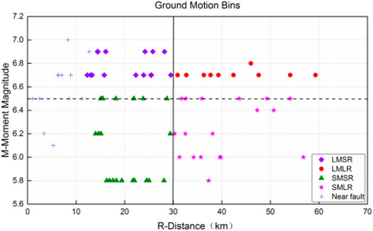
FIGURE 4. Mw-R distribution of ground motion records.
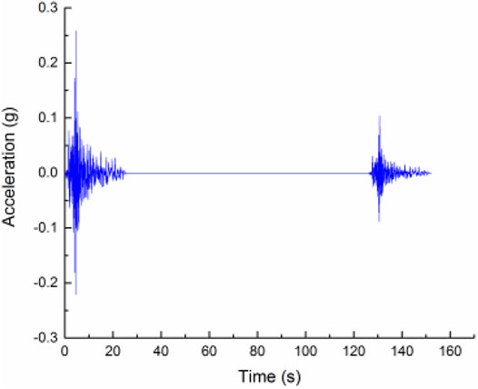
FIGURE 5. Acceleration time-history curves of mainshock-aftershock sequences (C08–320, PGAMS = 0.259 g).
Seismic Response Analysis of Single-Story Masonry Structures
Nonlinear seismic response analysis of the URM and CM structural models subjected to mainshocks only, aftershocks only, and mainshock-aftershock sequences was carried out using nonlinear dynamic time-history analysis. The maximum roof displacement and the maximum inter-story drift ratio (ISDR) are used as performance indices to evaluate the effects of confining members as well as aftershocks on the seismic response of single-story masonry structures.
Effect of Confining Members on Seismic Response of Masonry Structures Under Mainshocks
Table 1 lists the maximum values of roof displacement of the URM and CM structural models under mainshocks only. Compared with those of the URM structure, the maximum roof displacement of the CM model decrease by 2.13–66.81%. Taking the condition LOS-000 as an example, the maximum roof displacement of the URM model are 3.75 mm, while that of the CM model are 3.06 mm, representing a decrease of 18.4%. Evidently, the use of confining members such as ring beams and constructional columns improves the integrity of the single-story masonry structure and effectively reduces its seismic response.
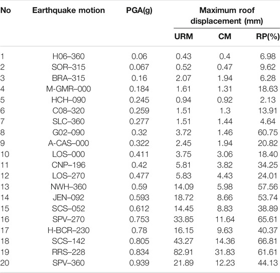
TABLE 1. Comparison of maximum roof displacements of single-story masonry structural models under different mainshocks.
Effect of Aftershocks on the Seismic Response of Mainshock-Damaged Masonry Structures
The nonlinear seismic response analysis of the URM and CM structural models under mainshock-aftershock sequences or aftershocks only was performed. Figure 6 shows the comparison of roof displacement time-history curves of the undamaged and mainshock-damaged URM and CM models under aftershock (LOS-000, PGAMS = 0.411 g, δ = 0.6). Tables 2 and 3 compare the maximum roof displacements of the URM and CM models under some of the main conditions. In Table 2 and 3, UD represents the undamaged model while MD represents Mainshock-damaged model. Compared with undamaged URM and CM models subjected to aftershock only, the maximum roof displacements of the mainshock-damaged URM and CM models subjected to aftershock of the same intensity increased by factors of 0–69.96 and 0–9.64, respectively, when δ = 0.4; by factors of 0–32.98 and 0–3.62 when δ = 0.6; by factors of 0–13.89 and 0–1.41 when δ = 0.8; and by factors of 0–7.72 and 0–1.29 when δ = 1. Taking the condition LOS-000 as an example, Figures 7, 8 compare the roof displacement time-history curves of the URM and CM models, respectively. When δ = 0.4, the maximum roof displacements of the undamaged URM and CM models under the aftershock only are 1.32 and 1.07 mm, respectively, while the maximum roof displacements of the two models under an aftershock of the same intensity after the mainshock are 2.65 and 1.89 mm, representing an increase of 100.8 and 76.6%, respectively. When δ = 0.6, the maximum roof displacements of the undamaged URM and CM models under the aftershock only are 1.99 and 1.60 mm, respectively, while the maximum roof displacements of the two models under the aftershock of the same intensity after the mainshock are 2.86 and 2.22 mm, representing an increase of 43.7 and 38.8%, respectively. When δ = 0.8, the maximum roof displacements of the undamaged URM and CM models under the aftershock only are 2.51 and 2.06 mm, respectively, while the maximum roof displacements of the two models under the aftershock of the same intensity after the mainshock are 3.34 and 2.72 mm, representing an increase of 33.1 and 32.0%, respectively. When δ = 1, the maximum roof displacements of the undamaged URM and CM models under the aftershock only are 3.75 and 3.06 mm, respectively, while the maximum roof displacements of the two models under the aftershock of the same intensity after the mainshock are 4.26 and 3.39 mm, representing an increase of 13.6 and 10.8%. Therefore, compared with undamaged URM and CM models under aftershock only, the roof displacement of the mainshock-damaged URM and CM models under the aftershock of the same intensity both notably increase, indicating that aftershocks have a substantial effect on the displacement demand of mainshock-damaged structures and hence cannot be ignored. In addition, as shown in Figure 6, it can be clearly seen that the presence of confining members effectively mitigates the effect of aftershocks on structures. Therefore, it is very important to have necessary confining members in masonry structures, which benefits resistance to not only a single strong earthquake but also multiple successive earthquakes.
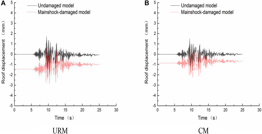
FIGURE 6. Comparison of roof displacement time-history curves of the undamaged and mainshock-damaged URM and CM models under aftershock (LOS-000, PGAMS = 0.411 g, δ = 0.6). (A) URM. (B) CM.
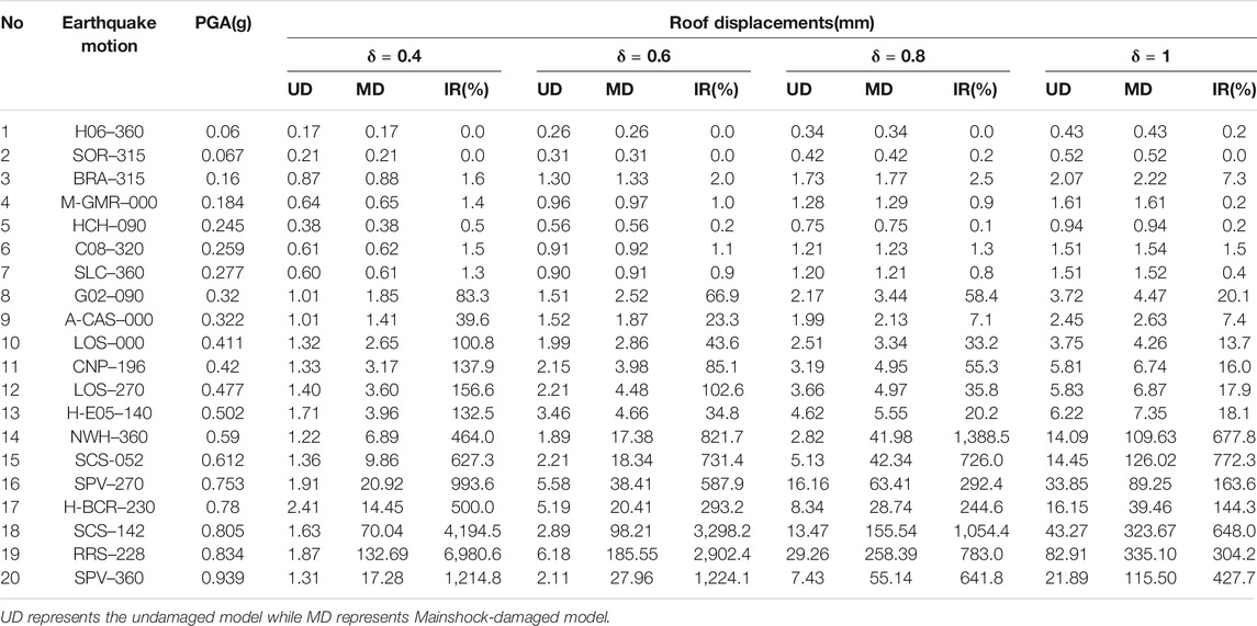
TABLE 2. Comparison of maximum roof displacements of the undamaged and mainshock-damaged URM models under aftershock.
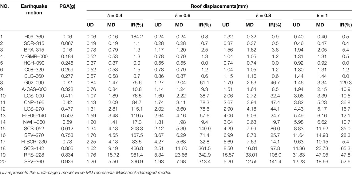
TABLE 3. Comparison of maximum roof displacements of the undamaged and mainshock-damaged CM models under aftershock.
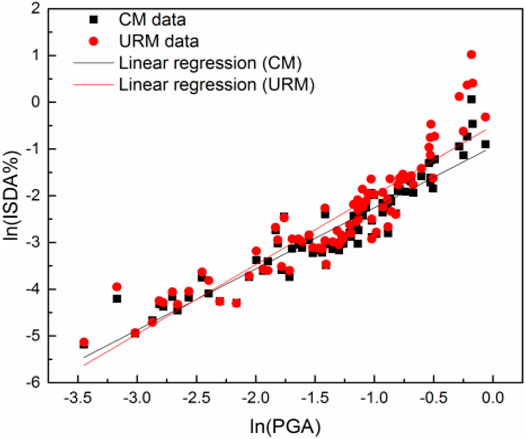
FIGURE 7. Probabilistic seismic demand model of URM and CM subjected to mainshock only.
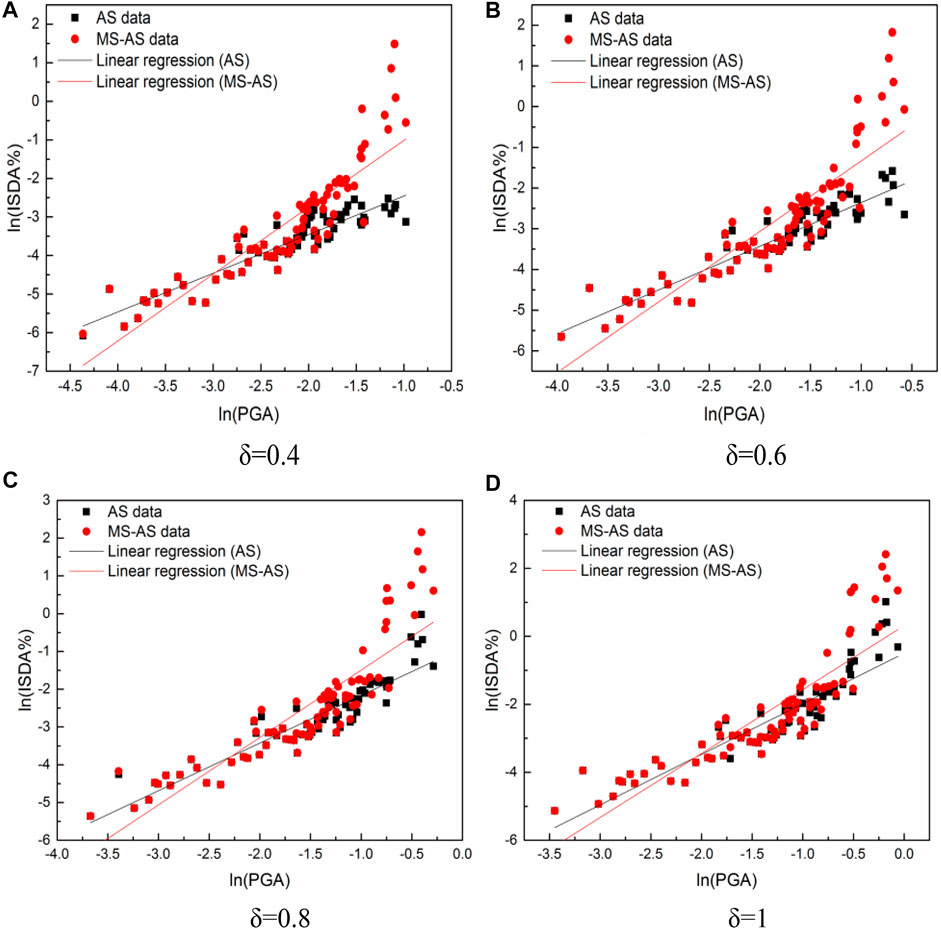
FIGURE 8. Probabilistic seismic demand model of URM subjected to aftershock. (A) δ = 0.4 (B) δ = 0.6 (C) δ = 0.8 (D) δ = 1.
Seismic Fragility Analysis of Single-Story Masonry Structures
Probabilistic Seismic Demand Model
The PSD model characterizes the relationship between the engineering demand parameter (EDP) and the ground motion intensity measure (IM). In the present study, the maximum ISDA (ISDAmax) and the peak ground acceleration (PGA) are selected as the EDP and the IM, respectively, for the PSD analysis of the two structures. Cornell et al. [39] proposed that the structural EDP and the IM satisfy the following logarithmic linear relation:
The PSD model under each condition can be obtained by fitting the results from the nonlinear dynamic time-history analysis of the structure. The logarithmic standard deviation of the seismic demand can be expressed as
where N is the number of sample points in the regression analysis, Di is the peak value of the ith seismic demand, IMi is the PGA of the ith ground motion, and a and b are the regression parameters.
Figure 7 shows the PSD models for the URM and CM models subjected to mainshocks only. Figures 8, 9 show the PSD models for the URM and CM models subjected to aftershocks only and mainshock-aftershock sequences. Tables 4 and 5 list the mathematical expressions and related parameters of the PSD models under different conditions.
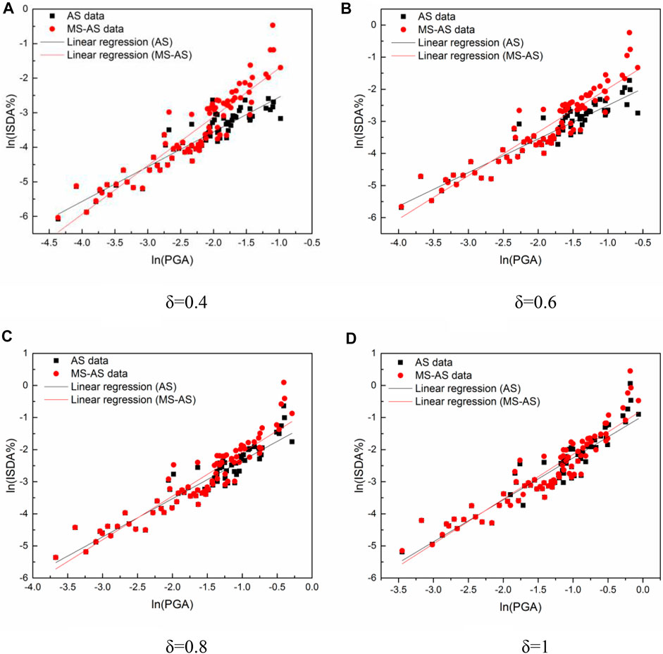
FIGURE 9. Probabilistic seismic demand model of CM subjected to aftershock. (A) δ = 0.4 (B) δ = 0.6 (C) δ = 0.8 (D) δ = 1.
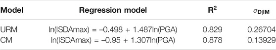
TABLE 4. Parameters for the probabilistic demand models of URM and CM subjected to mainshock only.
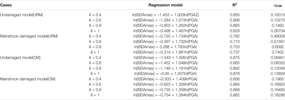
TABLE 5. Parameters for the probabilistic demand models of URM and CM subjected to aftershock.
Fragility Analytical Method
The fragility function can be expressed as follows [16]:
where D and C are seismic demand and structural capacity, respectively; IM is the ground motion intensity measure, μD and μC are the medians of D and C, respectively; and σD|IM and σC are the standard deviations corresponding to D and C, respectively.
The seismic fragility of a structure refers to the conditional probability that the structure reaches or exceeds a certain limit state under different seismic intensities. It thus describes the probability distribution of all limit states of the structure. Therefore, it is very important to define the damage limit states of the structure. Using the maximum ISDR as the EDP, four damage limit states, namely, slight damage (LS-1), moderate damage (LS-2), severe damage (LS-3), and collapse (LS-4), are defined according to the existing test results and recommended values for current specifications. Table 6 shows these damage limit states and their relevant parameters.
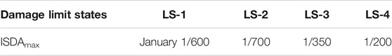
TABLE 6. Classification of damage limit states.
Fragility Results and Discussion
Effect of Confining Members on Seismic Fragility of Masonry Structures
Figure 10 compares the seismic fragility curves of the URM and CM models under mainshocks only. It is clear that the use of confining members is crucial to reducing the seismic fragility of masonry structures. The fragility curve of the CM model corresponding to each damage limit state is notably below that of the URM model. That is, the PE of each damage limit state of the CM model is lower than that of the URM model. Taking the case of PGA = 0.4 g as an example, the PE values of different damage limit states of the URM model are 98.75% (LS-1), 62.85% (LS-2), 11.06% (LS-3), and 0.53% (LS-4), while those of the CM model are 96.83% (LS-1), 34.59% (LS-2), 1.32% (LS-3), and 0.01% (LS-4), representing decreases of 1.94%, 44.96%, 88.07%, and 98.11%, respectively.
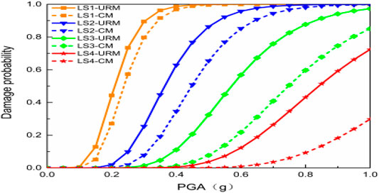
FIGURE 10. Comparison of fragility curves of the URM and CM model subjected to mainshock only.
Taking the case of the aftershock scaling factor δ = 1 as an example, Figure 11 shows the effect of confining members on the fragility curves of the mainshock-damaged URM and CM models subjected to aftershocks. The fragility curve of the mainshock-damaged URM model corresponding to each limit state is above that of the mainshock-damaged CM model, i.e., the PE of each damage limit state of the mainshock-damaged URM model is higher than that of the mainshock-damaged CM model. Taking the case of PGA = 0.4 g as an example, the PE values of the four damage limit states of the mainshock-damaged URM model are 98.83%, 77.66%, 46.19%, and 21.07%, respectively, and those of the mainshock-damaged CM model are 98.08, 47.09, 3.52%, and 4.77 × 10⁻⁴, representing decreases of 0.75%, 39.36%, 92.38%, and 99.77%, respectively. The presence of confining members significantly improves the structural resistance to aftershocks, as the likelihood of moderate damage, severe damage or collapse of the mainshock-damaged URM model (i.e., without confining members) subjected to the aftershock is higher than that of the mainshock-damaged CM model, as illustrated by the blue, green and red lines in Figure 11. Therefore, the use of confining members in the masonry structure has little effect on the slight damage state but can effectively reduce the likelihood of moderate damage, severe damage, or collapse of the mainshock-damaged masonry structure when subjected to aftershocks.
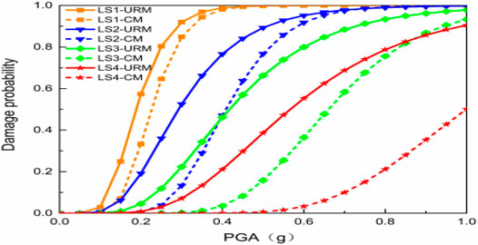
FIGURE 11. Effect of confining members on fragility curves of the mainshock-damaged CM and URM model subjected to aftershocks (δ = 1). Effect of Aftershocks on Seismic Fragility of Masonry Structures Under Aftershocks.
Figure 12 compares the fragility curves of the undamaged and mainshock-damaged CM models subjected to aftershocks. The PE values of damage limit states of the mainshock-damaged model subjected to the aftershock are significantly higher than those of the undamaged model directly subjected to the aftershock of the same intensity. As shown in Figure 12, taking the case of PGA = 0.4 g as an example, when δ = 0.4, the PE values of the four damage limit states of the CM model are 99.92%, 85.10%, 25.17%, and 1.63%, respectively, when subjected to the mainshock followed by an aftershock and are 85.10%, 9.31%, 0.06%, and 5.25 × 10⁻⁷ when subjected to the aftershock of the same intensity directly. That is, compared with the undamaged CM model, the aftershock increases the PE values of the damage limit states of the mainshock-damaged CM model by factors of 0.17, 8.14, 418.5, and 31,046.62, respectively. When δ = 0.6, the PE values of the four damage limit states of the CM model are 99.45, 64.07, 7.99, and 0.17%, respectively, when subjected to the mainshock followed by the aftershock; they are 88.38%, 12.1%, 0.01%, and 1.11 × 10⁻⁶, respectively, when directly subjected to the aftershock of the same intensity. That is, compared with the undamaged CM model, the aftershock increases the PE values of the damage limit states of the mainshock-damaged CM model by factors of 0.13, 4.30, 798, and 1,530.53, respectively. When δ = 0.8, the PE values of the four damage limit states of the CM model are 98.79%, 52.49%, 4.34%, and 5.99 × 10⁻⁴, respectively, when subjected to the mainshock followed by the aftershock and are 95.24%, 25.25%, 0.53%, and 1.42 × 10⁻⁵, when directly subjected to an aftershock of the same intensity. That is, compared with the undamaged CM model, the aftershock increases the PEs of the damage limit states of the mainshock-damaged CM model by factors of 0.04, 1.08, 7.19, and 41.18, respectively. When δ = 1, the PE values of the four damage limit states of the CM model are 98.08, 47.09, 3.52%, and 4.77 × 10⁻⁴, respectively, when subjected to the mainshock followed by the aftershock; they are 96.83%, 34.59%, 1.32%, and 7.48 × 10⁻⁵, when directly subjected to an aftershock of the same intensity. That is, compared with the undamaged CM model, the aftershock increases the PE values of the damage limit states of the mainshock-damaged CM model by factors of 0.01, 0.36, 1.67, and 5.38, respectively.
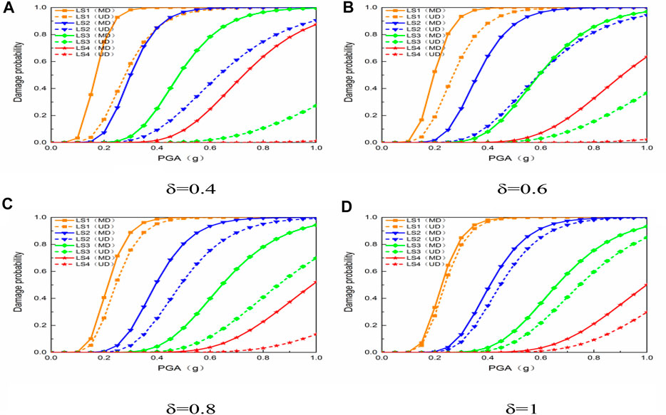
FIGURE 12. The fragility curves of the undamaged and mainshock-damaged CM model under aftershocks. (A) δ = 0.4 (B) δ = 0.6 (C) δ = 0.8 (D) δ = 1.
Figure 13 compares the fragility curves of the undamaged and mainshock-damaged URM model subjected to aftershocks. The PE values of the damage limit states of the mainshock-damaged URM model subjected to an aftershock are significantly higher than those of the undamaged URM model directly subjected to the aftershock of the same intensity. As shown in Figure 13, taking the case of PGA = 0.4 g as an example, when δ = 0.4, the PE values of the four damage limit states of the URM model are 99.95%, 97.13%, 78, 13%, and 42.43%, respectively, when subjected to the mainshock followed by the aftershock and are 90.22%, 14.88%, 0.17%, and 2.55 × 10⁻⁶ when directly subjected to an aftershock of the same intensity. That is, compared with the undamaged URM model, the aftershock increases the PE values of the damage limit states of the mainshock-damaged URM model by factors of 0.11, 553, 458, 47, and 16, 39, 116 respectively. When δ = 0.6, the PE values of the four damage limit states of the URM model are 99.6%, 90.59%, 59.09%, and 24.07%, respectively, when subjected to the mainshock followed by an aftershock; they are 94.34%, 22.77%, 0.42%, and 1.03 × 10⁻⁵ when directly subjected to an aftershock of the same intensity. That is, compared with the undamaged URM model, the aftershock increases the PE values of the damage limit states of the mainshock-damaged URM model by factors of 0.06, 2.98, 139.69, and 23, 367, 93, respectively. When δ = 0.8, the PE values of the four damage limit states of the URM model are 98.33%, 82.65%, 49.17%, and 19.84%, respectively, when subjected to the mainshock followed by an aftershock and are 98.14%, 43.92%, 2.47%, and 2.13 × 10⁻⁴ when directly subjected to an aftershock of the same intensity. That is, compared with the undamaged URM model, the aftershock increases the PE values of the damage limit states of the mainshock-damaged URM model by factors of 0.0019, 0.88, 18.91, and 930.46, respectively. When δ = 1, the PE values of the four damage limit states of the URM model are 98.83%, 76.66%, 46.19%, and 21.07%, respectively, when subjected to the mainshock followed by an aftershock; they are 98.75%, 62.85%, 11.06%, and 0.53% when directly subjected to an aftershock of the same intensity. That is, compared with the undamaged URM model, the aftershock increases the PE values of the damage limit states of the mainshock-damaged URM model by factors of 0.0008, 0.22, 3.18, and 38.75, respectively.
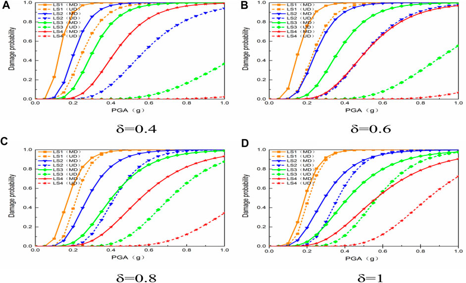
FIGURE 13. The fragility curves of the undamaged and mainshock-damaged URM model under aftershock. (A) δ = 0.4 (B) δ = 0.6 (C) δ = 0.8 (D) δ = 1.
Effect of the Aftershock Scaling Factor on the Seismic Fragility of Masonry Structures Under Aftershock
Figure 14 compares the fragility curves of the mainshock-damaged CM model using different aftershock scaling factors. As shown in Figure 14A, taking PGA = 0.2 g as an example and when δ = 0.4, 0.6, 0.8 and 1, the PE values of the slight damage limit state (LS-1) of the mainshock-damaged CM model is 0.43%, 5.78%, 14.91%, and 32.96%, respectively. In Figure 14B, taking PGA = 0.4 g as an example and when δ = 0.4, 0.6, 0.8 and 1, the PE values of the moderate damage limit state (LS-2) of the mainshock-damaged CM model are 1.22%, 9.01%, 22.98%, and 44.19%, respectively; taking PGA = 0.6 g as an example and when δ = 0.4, 0.6, 0.8 and 1, the PE values of the moderate damage limit state (LS-2) of the mainshock-damaged CM model are 21.35%, 49.99%, 76.35%, and 86.96%, respectively. As shown in Figure 14C, taking PGA = 0.6 g as an example and when δ = 0.4, 0.6, 0.8 and 1, the PE values of the severe damage limit state (LS-3) of the mainshock-damaged CM model are 0.62%, 4.77%, 14.52%, and 34.6%, respectively; taking PGA = 0.8 g as an example and when δ = 0.4, 0.6, 0.8 and 1, the PE values of the severe damage limit state (LS-3) of the mainshock-damaged CM model are 7.08%, 23.67%, 49.07%, and 69.33%, respectively. Figure 14D shows that, taking PGA = 0.8 g as an example and when δ = 0.4, 0.6, 0.8 and 1, the PE values of the collapse limit state (LS-4) of the mainshock-damaged CM model are 0.17, 1.57, 6.06, and 21.11%, respectively.
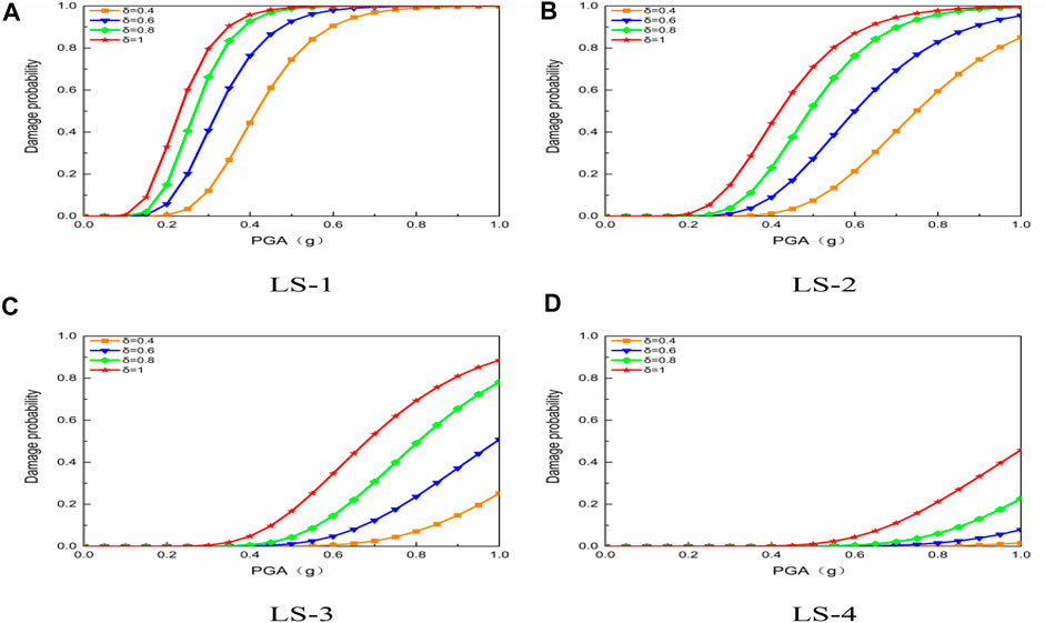
FIGURE 14. The fragility curves of the mainshock-damaged CM model under aftershock. (A) LS-1 (B) LS-2 (C) LS-3 (D) LS-4.
Figure 15 compares the fragility curves of the mainshock-damaged URM model using different aftershock scaling factors. As shown in Figure 15A, taking PGA = 0.2 g as an example and when δ = 0.4, 0.6, 0.8 and 1, the PE values of the slight damage limit state (LS-1) of the URM model are 8.22%, 26.68%, 41.33%, and 53.84%, respectively. Figure 15B shows that, taking PGA = 0.4 g as an example and when δ = 0.4, 0.6, 0.8 and 1, the PE values of the moderate damage limit state (LS-2) of the mainshock-damaged URM model are 22.26%, 46.66%, 64.5%, and 72.66%, respectively; taking PGA = 0.6 g as an example and when δ = 0.4, 0.6, 0.8 and 1, the PE values of the moderate damage limit state (LS-2) of the mainshock-damaged URM model are 66.11%, 83.35%, 92.14%, and 92.34%, respectively. As shown in Figure 15C, taking PGA = 0.6 g as an example and when δ = 0.4, 0.6, 0.8 and 1, the PE values of the severe damage limit state (LS-3) of the mainshock-damaged URM model are 23.92%, 47.9%, 67.34%, and 75.63%, respectively; taking PGA = 0.8 g as an example and when δ = 0.4, 0.6, 0.8 and 1, the PE values of the severe damage limit state (LS-3) of the mainshock-damaged URM model are 55.07%, 75.61%, 88.28%, and 89.98%, respectively. Figure 15D shows that, taking PGA = 0.8 g as an example and when δ = 0.4, 0.6, 0.8 and 1, the PE values of the collapse limit state (LS-4) of the mainshock-damaged URM model are 20.06, 42.71, 64.02, and 74.18%, respectively.
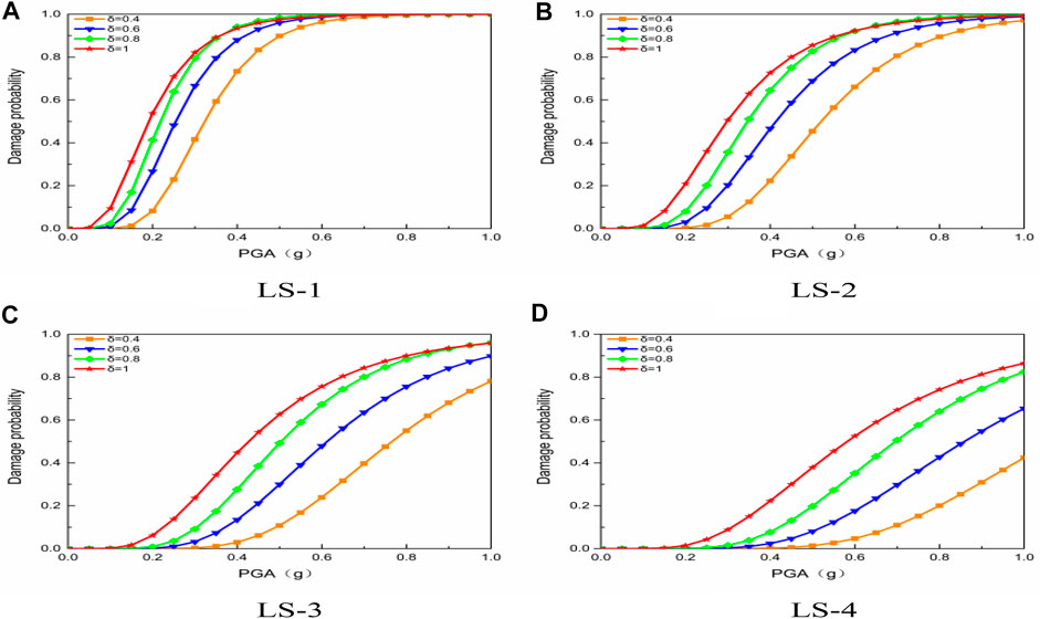
FIGURE 15. The fragility curves of the mainshock-damaged URM model under aftershock. (A) LS-1 (B) LS-2 (C) LS-3 (D) LS-4.
Conclusion
In this paper, the seismic fragility of single-story masonry structures representative of the rural areas of Northeast China is studied through numerical simulation. The effects of aftershocks and the aftershock scaling factor on the fragility of masonry structures are investigated in depth, taking into account the influence of confining members. The following main conclusions are drawn:
1) Compared with those of the URM model, the roof displacement and ISDRs of the CM model, which has ring beams and constructional columns, are both reduced to varying degrees, and the PE values of different damage limit states of the CM model are significantly lower. Therefore, it is necessary to use confining members in single-story masonry structures to improve their structural integrity, reduce their seismic responses, and effectively mitigate the risk of severe structural damage or collapse.
2) The effect of aftershocks on the seismic fragility of mainshock-damaged structures cannot be ignored. Compared with those of the undamaged URM and CM models directly under aftershock, the mainshock-damaged URM and CM models subjected to aftershocks of the same intensity undergo notably increased roof displacement and ISDA, and the PE values of their different damage limit states also increase substantially. In particular, aftershocks significantly affect the limit states of severe damage (LS-3) and collapse (LS-4). That is, after structures are subjected to the mainshock, the aftershock may raise the likelihood of severe damage or collapse.
3) Using confining members in the unreinforced masonry structures has little effect on the slight damage limit state (LS-1) but can effectively reduce the probability of moderate damage, severe damage, or collapse of masonry structures. Compared with the CM model, the URM model, which does not have confining members, exhibits a relatively high probability of moderate damage, severe damage or collapse when subjected to aftershocks. Therefore, it is extremely important to install the necessary con-fining members in masonry structures to bolster the resistance not only to single earthquakes but also to multiple successive earthquakes, thereby effectively reducing the probability of failure of structures subjected to single earthquakes or mainshock-aftershock sequences.
4) With the increase in PGA and aftershock scaling factor δ, the PE value of each damage limit state of the structures increases. Taking PGA = 0.8 g as an example, when δ = 0.4, 0.6, 0.8 and 1, the PE values of the collapse limit state (LS-4) of the CM model are 0.17, 1.57, 6.06, and 21.11%, respectively, while those of the URM model are 20.06, 42.71, 64.02, and 74.18%, indicating that the aftershock scaling factor affects the fragility of single-story masonry structures to some extent. It can also be seen that the aftershock scaling factor δ has a significant influence on the URM model for the lack of confining members.
5) The present study only uses the relatively simple replication method to construct mainshock-aftershock sequences. The attenuation relationship between mainshock and aftershock should also be investigated in depth based on as-recorded mainshock-aftershock sequences, to further develop reasonable methods for constructing rational mainshock-aftershock sequence-type ground motions. In addition, it is necessary to study the seismic performance and fragility of structures of various forms subjected to mainshock, aftershock and mainshock-aftershock sequences. The present study provides a theoretical reference for the seismic design and performance improvement of masonry structures.
Data Availability Statement
The datasets presented in this article are not readily available because embargo reason. Requests to access the datasets should be directed to Hao Zhang, h_zhang@sjzu.edu.cn.
Author Contributions
Conceptualization, HZ and TS. Methodology, HZ and S-WH. Software, Q-MG Formal analysis, S-WH and XL. Data curation, Q-MG and XL. Writing—original draft preparation, Q-MG and TS. Writing—review and editing, HZ. Project administration, HZ. Funding acquisition, HZ. All authors have read and agreed to the published version of the manuscript.
Funding
The authors are grateful for the financial support from the National Key R&D Program of China (2018YFD1100402) and the State Key Program of the National Natural Science Foundation of China (51738007) for carrying out this research.
Conflict of Interest
The authors declare that the research was conducted in the absence of any commercial or financial relationships that could be construed as a potential conflict of interest.
References
1. Zhang H, Li C, Wang ZF, Zhang CY. Seismic Performance Assessments of Precast Energy Dissipation Shear wall Structures under Earthquake Sequence Excitations. Earthquakes and Structures (2020) 18(2):147–62. doi:10.12989/eas.2020.18.2.147
2. Qu CX, Li HN, Huo LS, Yi TH. Optimum Value of Negative Stiffness and Additional Damping in the Civil Structures. ASCE J Struct Eng (2017) 143(8):04017068. doi:10.1061/(asce)st.1943-541x.0001805
3. Li H-N, Qu C, Huo L, Nagarajaiah S. Equivalent Bilinear Elastic Single Degree of freedom System of Multi-Degree of freedom Structure with Negative Stiffness. J Sound Vibration (2016) 365:1–14. doi:10.1016/j.jsv.2015.11.005
4. Qu C, Huo L, Li H, Wang Y. A Double Homotopy Approach for Decentralized H∞ Control of Civil Structures. Struct Control Health Monit (2014) 21(3):269–81. doi:10.1002/stc.1552
5. Gross JL, Phan LT. Implications for Earthquake Risk Reduction in the United States from the Kocaeli, Turkey, Earthquake of August 17, 1999. Reston, VA, United States: ASCE World Structural Engineering Conference (2000).
6. Yeo GL, Cornell CA. Stochastic Characterization and Decision Bases under Time-dependent Aftershock Risk in Performance-Based Earthquake Engineering. Berkeley, CA: Pacific Earthquake Engineering Research Center (2005).
7. Zheng Y, Ni S, Xie Z, Lv J, Ma H, Sommerville P. Strong Aftershocks in the Northern Segment of the Wenchuan Earthquake Rupture Zone and Their Seismotectonic Implications. Earth Planet Sp (2010) 62:881–6. doi:10.5047/eps.2009.06.001
8. Tiwari B, Wartman J, Pradel D. Slope Stability Issues after Mw 9.0 Tohoku Earthquake. San Diego, California, United States: Geo-congress (2013). p. 3–7.
9. Lim BJM, Leong EC. Characteristics of Landslides Induced by the 25 April 2015 M7.8 Nepal Earthquake. Geotechnical Earthquake Eng Soil Dyn (2018) 291:64–78. doi:10.1061/9780784481462.007
10. Song R, Li Y, Lindt JVD. Consideration of Mainshock-Aftershock Sequences into Performance-Based Seismic Engineering. Structures Congress (2013) 2161–7. doi:10.1061/9780784412848.189
11. Li Y, Song RL, Lindt JVD. Collapse Fragility of Steel Structures Subjected to Earthquake Mainshock-Aftershock Sequences. J Struct Eng (2014) 140:04014095. doi:10.1061/(asce)st.1943-541x.0001019
12. Nazari N, Lindt JVD, Li Y. Quantifying Changes in Structural Design Needed to Account for Aftershock hazard. J Struct Eng (2015) 141:04015035. doi:10.1061/(asce)st.1943-541x.0001280
13. Goda K, Taylor CA. Effects of Aftershocks on Peak Ductility Demand Due to strong Ground Motion Records from Shallow Crustal Earthquakes. Earthquake Eng Struct Dyn (2012) 41:2311–30. doi:10.1002/eqe.2188
14. Hosseinpour F, Abdelnaby AE. Effect of Different Aspects of Multiple Earthquakes on the Nonlinear Behavior of RC Structures. Soil Dyn Earthquake Eng (2017) 92:706–25. doi:10.1016/j.soildyn.2016.11.006
15. Wang Z, Pang Y, Yuan W. Fragility Analysis of a Continuous Gird Bridge Subjected to a Mainshock-Aftershock Sequence Considering Deterioration. Structures Congress (2017) 36–47. doi:10.1061/9780784480403.004
16. Zhang H, Li C, Jiang SM. Fragility Analysis of Concrete-filled Steel Tubular Frame Structures with BRBs under Multiple Earthquakes Considering Strain Rate Effects. Appl Sci (2020) 10:165. doi:10.3390/app10010165
17. Salami MR, Kashani MM, Goda K. Influence of Advanced Structural Modeling Technique, Mainshock-Aftershock Sequences, and Ground-Motion Types on Seismic Fragility of Low-Rise RC Structures. Soil Dyn Earthquake Eng (2019) 117:263–79. doi:10.1016/j.soildyn.2018.10.036
18. Pang R, Xu B, Zhou Y, Zhang X, Wang X. Fragility Analysis of High CFRDs Subjected to Mainshock-Aftershock Sequences Based on Plastic Failure. Eng Structures (2020) 206:110152. doi:10.1016/j.engstruct.2019.110152
19. Zhao C, Yu N, Peng T, Gautam A, Mo YL. Vulnerability Assessment of AP1000 NPP under Mainshock-Aftershock Sequences. Eng Structures (2020) 208:110348. doi:10.1016/j.engstruct.2020.110348
20. Han R, Li Y, Lindt JVD. Loss Estimation of Reinforced concrete Buildings Considering Aftershock Hazards. Structures Congress (2015) 2174–85. doi:10.1061/9780784479117.188
21. Nazari N, Lindt JVD, Li Y. Effect of Mainshock-Aftershock Sequences on wood Frame Building Damage Fragilities. J Perform Constructed Facil (2015) 29:04014036. doi:10.1061/(asce)cf.1943-5509.0000512
22.Southeast University; Tongji University; Zhengzhou University. Masonry Structure. 3rd. Beijing, China: China Architecture & Building Press (2013).
23. Zhao B, Taucer F, Rossetto T. Field Investigation on the Performance of Building Structures during the 12 May 2008 Wenchuan Earthquake in China. Eng Structures (2009) 31(8):1707–23. doi:10.1016/j.engstruct.2009.02.039
24. Bessason B, Bjarnason JÖ, Rupakhety R. Statistical Modelling of Seismic Vulnerability of RC, Timber and Masonry Buildings from Complete Empirical Loss Data. Eng Structures (2020) 209:109969. doi:10.1016/j.engstruct.2019.109969
25. Biglari M, Formsano A. Damage Probability Matrices and Empirical Fragility Curves from Damage Data on Masonry Buildings after Sarpol-E-Zahab and Bam Earthquakes of Iran. Front Built Environ (2020) 6:1–12. doi:10.3389/fbuil.2020.00002
26. Gaudio CD, Martino GD, Ludovico MD. Empirical Fragility Curves for Masonry Buildings after the 2009 L’Aquila, Italy, Earthquake. Bull earthquake Eng (2019) 17:6301–30. doi:10.1007/s10518-019-00683-4
27. Saloustros S, Pelà L, Contrafatto FR, Roca P, Petromichelakis I. Analytical Derivation of Seismic Fragility Curves for Historical Masonry Structures Based on Stochastic Analysis of Uncertain Material Parameters. Int J Architectural Heritage (2019) 13:1142–64. doi:10.1080/15583058.2019.1638992
28. Chellappa S, Dubey RN. Performance Evaluation of a Reinforced Masonry Model and an Unreinforced Masonry Model Using a Shake Table Testing Facility. J Perform Constructed Facil (2018) 32:04017121. doi:10.1061/(asce)cf.1943-5509.0001119
29. Bagheri B, Lee J-H, Kim H-G, Oh S-H. Experimental Evaluation of the Seismic Performance of Retrofitted Masonry walls. Compos Structures (2020) 240:111997. doi:10.1016/j.compstruct.2020.111997
30. Ghezelbash A, Beyer K, Dolatshahi KM, Yekrangnia M. Shake Table Test of a Masonry Building Retrofitted with Shotcrete. Eng Structures (2020) 219:110912. doi:10.1016/j.engstruct.2020.110912
31. Qu C-X, Yi T-H, Li H-N, Chen B. Closely Spaced Modes Identification through Modified Frequency Domain Decomposition. Measurement (2018) 128:388–92. doi:10.1016/j.measurement.2018.07.006
32. Kaushik HB, Rai DC, Jain SK. Stress-strain Characteristics of clay brick Masonry under Uniaxial Compression. J Mater Civ Eng (2007) 19:728–39. doi:10.1061/(asce)0899-1561(2007)19:9(728)
33.National Standards of the People’s Republic of China. Code for Design of Concrete Structures; GB 50010-2010. Beijing, China: Standards Press of China (2010).
34. Han RL, Li Y, Lindt JVD. Assessment of Seismic Performance of Buildings with Incorporation of Aftershocks. J Perform Constructed Facil (2015) 29:04014088. doi:10.1061/(asce)cf.1943-5509.0000596
35. Zhai C-H, Wen W-P, Li S, Chen Z, Chang Z, Xie L-L. The Damage Investigation of Inelastic SDOF Structure under the Mainshock-Aftershock Sequence-type Ground Motions. Soil Dyn Earthquake Eng (2014) 59:30–41. doi:10.1016/j.soildyn.2014.01.003
36. Hatzigeorgiou GD, Beskos DE. Inelastic Displacement Ratios for SDOF Structures Subjected to Repeated Earthquakes. Eng Structures (2009) 31:2744–55. doi:10.1016/j.engstruct.2009.07.002
37. Li Q, Ellingwood BR. Performance Evaluation and Damage Assessment of Steel Frame Buildings under Main Shock-Aftershock Earthquake Sequences. Earthquake Eng Struct Dyn (2010) 36:405–27. doi:10.1002/eqe.667
38. Mackie K, Stojadinovi´c B. Fragility Basis for California Highway Overpass Bridge Seismic Decision Making; PEER Report No. 2005/02; Pacific Earthquake Engineering Research Center. Berkeley, CA, USA: University of California (2005).
Keywords: masonry structure, aftershock, fragility, seismic performance, probabilistic seismic demand analysis
Citation: Zhang H, Sun T, Hou S-W, Gao Q-M and Li X (2021) Effect of Aftershocks on Seismic Fragilities of Single-Story Masonry Structures. Front. Phys. 9:695111. doi: 10.3389/fphy.2021.695111
Received: 14 April 2021; Accepted: 10 May 2021;
Published: 28 May 2021.
Edited by:
Chun-Xu Qu, Dalian University of Technology, ChinaCopyright © 2021 Zhang, Sun, Hou, Gao and Li. This is an open-access article distributed under the terms of the Creative Commons Attribution License (CC BY). The use, distribution or reproduction in other forums is permitted, provided the original author(s) and the copyright owner(s) are credited and that the original publication in this journal is cited, in accordance with accepted academic practice. No use, distribution or reproduction is permitted which does not comply with these terms.
*Correspondence: Tong Sun, dHN1bkBzanp1LmVkdS5jbg==; Shi-Wei Hou, aHN3MTM3NUAxMjYuY29t