- 1College of Electronics and Information Engineering, Shenzhen University, Shenzhen, China
- 2School of Electrical and Data Engineering, University of Technology Sydney, Ultimo, NSW, Australia
The dielectric waveguide in THz and millimeter circuit is widely researched. However, it is rarely researched in a microwave frequency. In this article, a dielectric rod waveguide (DRW) is proposed with low transmission loss in microwave frequency. For the purpose of impedance matching, a transition section composed of the metal-coated dielectric cavity, and a dielectric horn is presented to match the impedance between the coaxial cable and the dielectric rod waveguide. Finally, the dielectric rod waveguide and the transition section have been fabricated for experimental verification. To obtain the propagation constant of the DRW, the thru-line (TL) calibration is used in measurement. The simulation and measurement results show an effective conversion between the coaxial cable and the dielectric rod waveguide.
Introduction
Waveguide is an important passive component in electronic circuits. Due to the low transmission loss of the dielectric waveguide in millimeter and THz frequency ranges, various dielectric waveguides [1] are designed to connect different electronic devices and establish an interconnected network between the chips. Most dielectric waveguides can be divided into solid, hollow, and porous waveguides [2] depending on the geometry. Among them, the dielectric rod waveguide is the main dielectric waveguide structure due to its simple structure and low processing cost. However, most of the literature reports have studies dielectric waveguides working in a millimeter frequency or above. The fabrication of dielectric waveguides in the millimeter and terahertz frequency requires high precision machining processes.
In microwave frequency, the dielectric material has good radiation properties and can be fabricated into dielectric rod waveguide antennas [3, 4]. In order to reduce the radiation loss, some non-radiative dielectric (NRD) waveguides working in microwave frequency are reported in the articles mentioned in references [5–8]. However, these NRD waveguides require a metal in the waveguide transmission line structure. The full dielectric waveguide working in microwave frequency [9] is rarely mentioned, which can help explore the non-traditional new dielectric waveguide transmission line structure and new microwave components in the microwave frequency.
The conversion structures between the traditional metal transmission lines and the dielectric waveguides have been widely studied. The dielectric tapering transition sections [10–12] indicate the high conversion efficiency between the metal rectangular waveguides and the solid dielectric waveguides. However, this transition structure usually needs an additional support arm to hold the dielectric tapering transition structure over the center of the metal rectangular waveguide. Besides, the dielectric waveguides can be fed in and extracted from energy through a non-contact method. Transmitting and receiving antennas need to be designed to implement this method, as in the studies mentioned in references [13, 14]. In addition, a complex transition structure consisting of a spherical dielectric resonator and a non-radiative dielectric waveguide is proposed in the study mentioned in reference [15]. This kind of transition enables low conversion loss between the dielectric waveguide and the microstrip in millimeter integrated circuits.
In this article, we present the dielectric rod waveguide with a rectangular cross section in microwave frequency. In order to connect the DRW with the coaxial cable, a transition structure composed of the metal-coated dielectric cavity and dielectric horn is proposed. Simulation and measurement are in good agreement. The results show that the transmission loss of the dielectric rod waveguide is low, and the transition between the coaxial cable and the dielectric rod waveguide is effective from 7.12 to 9.4 GHz. The designed dielectric rod waveguide and the conversion structure are able to apply for further design of dielectric interconnect circuits and novel microwave components.
Structure of Dielectric Rod Waveguide
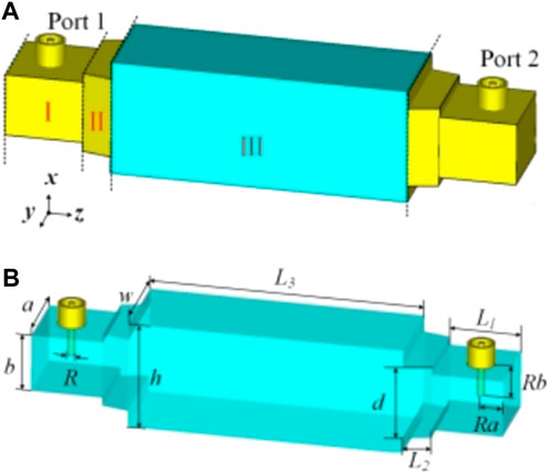
The structure of the designed dielectric rod waveguide and the conversion section are divided into three parts, as shown in Figure 1A. Introduction is about the metal-coated dielectric cavity connected to a 50 Ω coaxial cable. The height Rb and the length Ra of the coaxial probe position are used to match the impedance between the coaxial cable and the metal-coated dielectric cavity [16]. Structure of Dielectric Rod Waveguide is the metal-coated dielectric horn. The width of the metal-coated dielectric horn is gradually increased from the width a of the metal-coated dielectric cavity to the width w of the dielectric rod waveguide. Experimental Results is about the dielectric rod waveguide which is composed of the dielectric material with 3.55 permittivity constant and 0.0027 loss tangent.

FIGURE 1. (A) Designed structure of the dielectric rod waveguide and the conversion structure. The height of the metal coating is 0.035 mm. (B) Portion of the dielectric material of the entire structure and two coaxial cables at two ports, in which a = 14.5, b = 10.668, R = 1.3, Ra = 5.7, Rb = 5.8, d = 13.716, w = 18, h = 19.812, L1 = 13, L2 = 5, and L3 = 50 (all in mm). (Dielectric material is blue, and the metal is yellow.)
The electric field distribution at the xoz plane is shown in Figure 2. In Experimental Results, the electromagnetic (EM) wave mode of the dielectric rod waveguide is in the Ex11 mode [17], which also means that the electric field is mainly distributed in the x and z directions and the magnetic field is mainly distributed in the y and z directions. Most of the electromagnetic waves are trapped in the dielectric rod waveguide, and a small part is distributed in the surrounding air. The designed DRW is connected to the coaxial cables at both ends through two conversion structures. The metal-coated dielectric cavity converts the wave mode of the coaxial cable into a TE10 mode. The TE10 mode of the metal-coated dielectric cavity is then converted to the Ex11 mode of the DRW. Thus, the metal-coated dielectric horn provides a smooth transition between the two wave modes.

FIGURE 2. Electric field distribution at 8 GHz of the designed dielectric rod waveguide and the conversion structure. (A) XOZ plane. (B) XOZ plane.
Experimental Results
Resource Identification Initiative
In order to verify the properties of the designed dielectric rod waveguide and the conversion structure, two structures with different DRW lengths have been manufactured. The 50 Ω SMA connectors are welded on the top side. Figure 3A shows the photography of the longer dielectric rod waveguide with a length of 100 mm and the short dielectric rod waveguide with a length of 50 mm. In practical fabrication, the dielectric waveguides and the conversion structures are stacked by multilayer substrates with a permittivity constant of 3.55, which are shown in Figure 3B. The metal coating on the side wall is replaced by multiple copper-plated holes. In addition, the large holes on the left and right sides of each layer are used to insert screws to ensure alignment between all printed circuit boards.

FIGURE 3. (A) Photograph of two structures with different lengths of DRW. (B) Assembly of the 50-mm-long dielectric rod waveguide and the conversion structure.
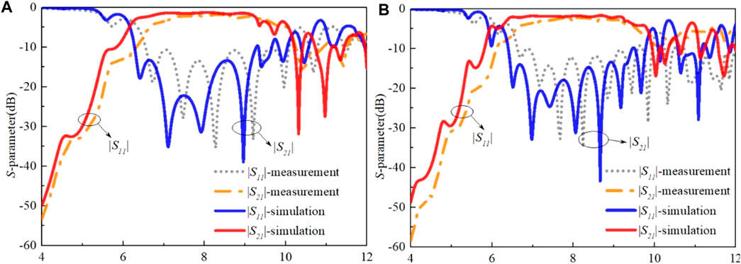
The simulated and measured results of the two structures with different DRW lengths are presented in Figure 4. CST microwave studio (CST-WMS) is used for simulation. The Agilent Technologies E5071C is used to test the S parameters of the two structures with different DRW lengths. The measurement results agree with the simulation results. In Figure 4A, the measured |S11| of the structure with a length of 50 mm DRW is below −10 dB from 7.12 to 9.4 GHz, and the insertion loss |S21| is −1.88 dB at the center frequency. The fractional bandwidth is about 27.6%. Meanwhile, in Figure 4B, the measured |S11| of the structure with a length of 100 mm DRW is also below −10 dB from 7.12 to 9.4 GHz, and the measured |S21| is −2.21 dB at 8.26 GHz. The error between the simulation and the measurement may be caused by the machining error and the assembly error.

FIGURE 4. (A) Simulation and measurement results of the structure with a length of 50 mm DRW. (B) Simulation and measurement results of the structure with a length of 100 mm DRW.
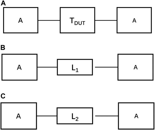
In order to obtain the actual propagation parameters, the attenuation constant α and the propagation constant β, the thru-line (TL) calibration is used. Since the matching network is introduced to excite the total structure, it can affect the results of the core DWG. The TL calibration can be understood as a simplified case of TRL calibration, which is used in measurement and the numerical method [18, 19, 20]. In this calibration, the two standards, called through and line, are used to de-embed the two symmetrical error boxes. In the TL calibration method, two calibration standards, called through and line, are used. In the practical experience, two different lengths of transmission line (L1 and L2) are used to realize the thru and line standards. And the T-matrix under these two cases can be called as TT and TL. These two calibration kits are similar to the thru and line calibration kit in thru-reflect-line (TRL). Based on the symmetry of the error box, it can only use those two calibration kits. The TL calibration is powerful to model the guided wave structures and substrate-integrated circuits and to extract the parameters of the microwave circuits. This method can be easily implemented into commercial software for many types of microwave circuits. The theory derivation will be given as follows, as described in references [19, 20].
Figures 4, 5 indicates the two-port equivalent network and the two standard elements in the TL method. The T-matrix under different circumstances can be written as follows:
where TM, TDUT, and A are the T-matrix of the total two-port network, DUT, and error boxes, respectively, in Figure 5A, and γ is the determined propagation constant of the lines used in the line standard.

FIGURE 5. Schematic diagrams of numerical TL de-embedding procedure and the two standards in TRL. (A) Two-port equivalent network under the numerical TL calibration. (B) Through standard. (C) Line standard.
Because the two error boxes are symmetrical, the relation between A and
where A−1 denotes the inverse of the matrix A. For a simple expression, we define Q as follows:
Substituting Eq. 1 into Eq. 2, the eigenvalue problem can be obtained as follows:
where L is the difference between the through and line standards, namely, L = L2-L1. And the columns of the matrix A can be considered as the eigenvector of Q. The propagation constant γ can be solved by the eigenvalue problems as given follows:
where L is the difference between the through and line standards, namely, L = L2-L1。.
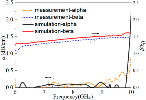
The matching network of this design works the error box in the TL calibration, which needs to be removed. After deembedding the error box, the accurate results of the transmission dielectric rod waveguide can be obtained. Figures 5, 6 shows the measured and simulated attenuation constant α and the propagation constant β. Those results agree well with each other. It can be found that α increases when the operating frequency is up to 9.7 GHz, working as a stopband. β/k0 is larger than 1 over the whole frequency band, working as the slow wave. So there is no leaky wave, and less radiation wave radiates from the dielectric waveguide. It can serve as a low loss transmission line.

FIGURE 6. Attenuation constant and normalized propagation constant calculated by the simulation and measurement results. k0 is the propagation constant in the free space.
Conclusion
In this work, a dielectric rod waveguide in a microwave band has been presented. For an impedance matching purpose, a transition between the coaxial cable and the designed DRW is designed from 7.12 to 9.4 GHz. The metal coated dielectric cavity and a dielectric horn convert the wave mode of the coaxial cable into the Ex11 mode of the dielectric rod waveguide. In order to verify the transmission and transition properties, two dielectric rod waveguides with different transmission line lengths and the same conversion sections are fabricated and tested. The designed dielectric rod waveguide and the conversion section have the potential to advance in developing novel microwave components.
Data Availability Statement
The original contributions presented in the study are included in the article/Supplementary Material; further inquiries can be directed to the corresponding author.
Author Contributions
The first author YL simulated the results and TL calibration theory. S-YZ simulated some structures and measured results. S-WW provided the theoretical analysis. J-YL helped with the theoretical analysis.
Funding
This work was supported in part by the Shenzhen Science and Technology Programs (Grant/Award Numbers: JCYJ20190808145411289 and JCYJ20180305124543176); Natural Science Foundation of Guangdong Province (Grant/Award Number: 2018A030313481); Shenzhen University Research Start up Project of New Staff (Grant/Award Number: 860-000002110311); and Guangdong Basic and Applied Basic Research Foundation, Grant/Award Number: 2019A1515111166.
Conflict of Interest
The authors declare that the research was conducted in the absence of any commercial or financial relationships that could be construed as a potential conflict of interest.
Publisher’s Note
All claims expressed in this article are solely those of the authors and do not necessarily represent those of their affiliated organizations, or those of the publisher, the editors, and the reviewers. Any product that may be evaluated in this article, or claim that may be made by its manufacturer, is not guaranteed or endorsed by the publisher.
Acknowledgments
This is short text to acknowledge the contributions of specific colleagues, institutions, or agencies that aided the efforts of the authors.
References
1. Yu B, Liu Y, Ye Y, Ren J, Liu X, Gu QJ. High-efficiency Micromachined Sub-THz Channels for Low-Cost Interconnect for Planar Integrated Circuits. IEEE Trans Microwave Theor Techn (2016) 64(1):96–105. doi:10.1109/TMTT.2015.2504443
2. Atakaramians S, Shahraan A.V, Bernd M, Abbott D, Monro TM. Porous Fibers: a Novel Approach to Low Loss THz Waveguides. Opt Express (2008) 16(12):8845–54. doi:10.1364/OE.16.008845
3. Kazemi R, Fathy AE, Sadeghzadeh RA. Dielectric Rod Antenna Array with Substrate Integrated Waveguide Planar Feed Network for Wideband Applications. IEEE Trans Antennas Propagat (2012) 60(3):1312–9. doi:10.1109/TAP.2011.2182489
4. Lugo DC, Ramirez RA, Wang J, Weller TM. Multilayer Dielectric End-Fire Antenna with Enhanced Gain. Antennas Wirel Propag Lett (2018) 17(12):2213–7. doi:10.1109/LAWP.2018.2871103
5. Yoneyama T, Nishida S. Nonradiative Dielectric Waveguide for Millimeter-Wave Integrated Circuits. IEEE Trans Microwave Theor Techn (1981) 29(11):1188–92. doi:10.1109/TMTT.1981.1130529
6. Liang Han L, Ke Wu RG, Bosisio RG. An Integrated Transition of Microstrip to Nonradiative Dielectric Waveguide for Microwave and Millimeter-Wave Circuits. IEEE Trans Microwave Theor Techn (1996) 44(7):1091–6. doi:10.1109/22.508642
7. Kwan GKC, Das NK. Excitation of a Parallel-Plate Dielectric Waveguide Using a Coaxial Probe-Basic Characteristics and Experiments. IEEE Trans Microwave Theor Techn (2002) 50(6):1609–20. doi:10.1109/TMTT.2002.1006423
8. Massoni E, Espin-Lopez PF, Pasian M, Bozzi M, Perregrini L, Alaimo G, et al. 3D-printed Chalk Powder for Microwave Devices: Experimental Results for a NRD-Guide in Ku-Band. in: 2017 47th European Microwave Conference (EuMC); 10–12 Oct 2017; Nuremberg, Germany. IEEE. p. 504–7. doi:10.23919/EuMC.2017.8230900
9. Lugo DC, Ramirez RA, Castro J, Wang J, Weller TM. Ku-band Additive Manufactured Multilayer Dielectric Rod Waveguide. in: 2017 IEEE 18th Wireless and Microwave Technology Conference (WAMICON); 24-25 April 2017; Cocoa Beach, FL, USA. IEEE. p. 1–3. doi:10.1109/wamicon.2017.7930260
10. Yeh C, Shimabukuro F, Siegel PH. Low-loss Terahertz Ribbon Waveguides. Appl Opt (2005) 44(28):5937–46. doi:10.1364/AO.44.005937
11. Ranjkesh N, Basha M, Taeb A, Safavi-Naeini S. Silicon-on-glass Dielectric Waveguide-Part II: for THz Applications. IEEE Trans Thz Sci Technol (2015) 5(2):280–7. doi:10.1109/TTHZ.2015.2397279
12. Malekabadi A, Charlebois SA, Deslandes D, Boone F. High-resistivity Silicon Dielectric Ribbon Waveguide for Single-Mode Low-Loss Propagation at F/G-bands. IEEE Trans Thz Sci Technol (2014) 4(4):447–53. doi:10.1109/TTHZ.2014.2322513
13. Zhu H-T, Xue Q, Hui J-N, Pang SW. A 750-1000 GHz $H$ -Plane Dielectric Horn Based on Silicon Technology. IEEE Trans Antennas Propagat (2016) 64(12):5074–83. doi:10.1109/TAP.2016.2620471
14. Caglayan C, Trichopoulos GC, Sertel K. Non-contact Probes for On-Wafer Characterization of Sub-millimeter-wave Devices and Integrated Circuits. IEEE Trans Microwave Theor Techn (2014) 62(11):2791–801. doi:10.1109/TMTT.2014.2356176
15. Dey U, Hesselbarth J. Building Blocks for a Millimeter-Wave Multiport Multicast Chip-To-Chip Interconnect Based on Dielectric Waveguides. IEEE Trans Microwave Theor Techn (2018) 66(12):5508–20. doi:10.1109/TMTT.2018.2873356
17. Goell JE. A Circular-Harmonic Computer Analysis of Rectangular Dielectric Waveguides. Bell Syst Tech. J. (1969) 48(7):2133–60. doi:10.1002/j.1538-7305.1969.tb01168.x
18. Zhu H-T, Xue Q. Determination of Propagation Constant of Terahertz Dielectric ridge Waveguide Using Noncontact Measurement Approach. IEEE Trans Instrum Meas (2017) 66(8):2118–28. doi:10.1109/TIM.2017.2685118
19. Ke Wu F, Wu K. Guided-wave and Leakage Characteristics of Substrate Integrated Waveguide. IEEE Trans Microwave Theor Techn (2005) 53(1):66–73. doi:10.1109/TMTT.2004.839303
Keywords: coaxial cable, dielectric rod waveguide (DRW), microwave frequency, transition, microwave frequency band
Citation: Li Y, Zhou S-Y, Wong S-W and Lin J-Y (2021) Transition Structure Between Coaxial Cable and Dielectric Rod Waveguide in Microwave Frequency. Front. Phys. 9:765801. doi: 10.3389/fphy.2021.765801
Received: 27 August 2021; Accepted: 06 September 2021;
Published: 19 October 2021.
Edited by:
Gang Zhang, Nanjing Normal University, ChinaReviewed by:
Yijing He, Beijing Institute of Technology, ChinaMing Jiang, University of Electronic Science and Technology of China, China
Copyright © 2021 Li, Zhou, Wong and Lin. This is an open-access article distributed under the terms of the Creative Commons Attribution License (CC BY). The use, distribution or reproduction in other forums is permitted, provided the original author(s) and the copyright owner(s) are credited and that the original publication in this journal is cited, in accordance with accepted academic practice. No use, distribution or reproduction is permitted which does not comply with these terms.
*Correspondence: Sai-Wai Wong, d29uZ3NhaXdhaUBpZWVlLm9yZw==
 Yin Li
 Shi-Yan Zhou1