 Liguo Jin
 Hongyang Sun
 Shengnian Wang
 Zhenghua Zhou4,3
- 1Institute of Geophysics, China Earthquake Administration, Beijing, China
- 2Department of Civil Engineering and Architecture, Yantai Vocational College, Yantai, China
- 3College of Transportation Engineering, Nanjing Tech University, Nanjing, China
- 4Institute of Engineering Mechanics, Nanjing Tech University, Nanjing, China
This paper presents a closed-form series solution of cylindrical SH-wave scattering by the surrounding loose rock zone of underground tunnel lining in a uniform half-space based on the wave function expansion method and the mirror image method. The correctness of the series solution is verified through residual convergence and comparison with the published results. The influence of the frequency of the incident cylindrical SH-wave, the distance between the wave source and the lining, the lining buried depth, and the properties of the surrounding loose rock zone on the dynamic stress concentration of the tunnel lining is investigated. The results show that the incident wave with high frequency always makes the dynamic stress concentration of the tunnel lining obvious. With the increase of the distance between the wave source and the tunnel lining, the stress around the tunnel lining decreases, but the dynamic stress concentration factor around the tunnel lining does not decrease significantly but occasionally increases. The ground surface has a great influence on the stress concentration of the tunnel lining. The amplitude of the stress concentration factor of tunnel lining is highly related to the shear wave velocity of the surrounding loose rock zone. When the property of the surrounding rock (shear wave velocity) changes more, the amplitude of the stress concentration factor is larger, that is, the stress concentration is more significant.
Introduction
The scattering of elastic waves by an underground cavity (or local topography) is one of the hot research topics in the fields of earthquake engineering, seismology, and geophysics due to its particular significance in seismic risk assessment, seismic microzonation, and the design of important facilities. When the seismic wave encounters a cavity (or local topography) during its propagation, it will produce a strong scattering effect, which in turn will affect the ground motion near the cavity (or local topography). The method of solving the problem of wave scattering can be divided into two kinds of methods: numerical method and analytical method. Numerical methods mainly include the finite difference method (FDM), finite element method (FEM), and boundary element method (BEM); the analytical methods mainly refer to wave function expansion methods. The numerical method can be applied to the cavity (or local topography) of any shape and various site conditions and is more suitable for handling actual engineering problems. The analytical method is still necessary to solve some special regular cavity (or local topography) and boundary conditions. Although the analytical method is only suitable for relatively simple and regular models, it has an advantage over the numerical method in revealing the essence of the problem, and it can also verify the accuracy of the numerical method.
For plane waves, beginning with the pioneering work of Trifunac [1, 2] on ground motion around a semi-circular alluvial valley and a semi-circular canyon embedded in a homogeneous isotropic half-space, several research works have been carried out on this topic both analytically and numerically. For the underground tunnel lining, the current closed-form analytical solutions are Refs. [3, 4]. For canyon topography, the present analytical solutions are Taur et al. [5], Gao et al. [6], Zhang et al. [7], Jin et al. [8–10], and Lee et al. [11, 12]. In addition, various numerical methods mainly include the finite difference method [13, 14], the improved Bouchon–Campillo method [15], the boundary integral equation method [16, 17], the null-field boundary integral equation method [18], the weighted residual method [19–21], and the boundary element method [22–29]. These research works have been widely reviewed by many scholars such as Sanchez-Sesma et al. [30], Liu et al. [31], Gao et al. [6], and Bhatti and Lu [39, 40].
For cylindrical waves, Liang et al. [32] studied the scattering of cylindrical SH-waves by underground lining caverns using the mirror image method. Li [33] investigated the numerical solution of the cylindrical SH-wave scattering by a circular hole. Zhang [34] studied the scattering of cylindrical waves by underground circular sandwiched areas and lining caverns in the half-space by using a special boundary integral equation method. Xu et al. [35] investigated the diffraction of Rayleigh waves around a circular cavity in the poroelastic half-space by using an indirect boundary integral equation method based on Biot’s two-phase medium theory.
This paper notices that the above-mentioned studies are mostly aimed at plane SH-waves and do not consider the impact of cylindrical SH-waves on the surrounding rock zone (i.e., the generation of loose circles) generated during cavity blasting and excavation. Therefore, this paper establishes an analytical model for the scattering of cylindrical SH-waves by loose rock circles around the underground lining cavern embedded in a 2D homogenous half-space and uses the wave function expansion method to obtain the series solution of scattering.
In the next section, the methodology is presented, followed by the verification through residual convergence and comparison with the published results of Liang et al [32]. Then, the results in the frequency domain are presented, and the anti-plane tunnel responses are discussed. Finally, the main findings and the conclusions are summarized.
Methodology
Analytical Model
As shown in Figure 1A, the inner and outer radii of the circular lined tunnel are a and b (b = 0.9a), respectively. The surrounding loose rock zone is divided into j layers, and the radius of each layer is c1, c2, c3, cj … from inside to outside. The burial depth of the circular lined tunnel is D. The half-space, the surrounding loose rock zone, and the lining are assumed to be linearly elastic, uniform, and isotropic media. The half-space is marked with shear wave velocity
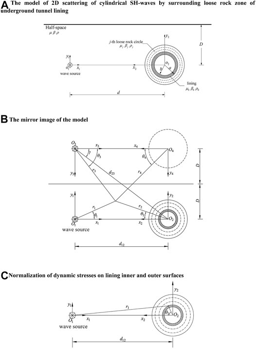
FIGURE 1. Model information.
Governing Equations and Boundary Conditions
The cylindrical SH-wave with unit amplitude generated by the wave source at point O1 can be expressed as
where
The reflected wave will be generated when the incident cylindrical SH-wave propagates to the ground surface, and a scattered SH-wave will be generated when the incident cylindrical SH-wave encounters a cavity. Then, the total wave motion field in the half-space is the superposition of the incident wave, reflected wave, and scattered wave. Meanwhile, the wave will also diffract into the lining and surrounding loose rock, and all these waves must satisfy the following wave equation:
To satisfy the zero-stress boundary condition of the half-space surface, the mirror image method [3] is used to solve the problem. As shown in Figure 1B, assume that there is another cylindrical wave source and cavity with the same surrounding loose rock zone in the half-space with the surface as its axis of symmetry. The mirror incident SH-wave source
The scattered wavefield corresponding to the two cavities can be expressed as
In a physical sense, Eq. 5 represents the wave propagating outward from O2 and O4 in the whole space and satisfies the wave equation (3) and Sommerfeld radiation conditions.
The expression of the scattered field generated in the lining in the polar coordinate system
Here,
The expression of the scattered wavefield generated in the loose rock circle in the polar coordinate system
Here,
All the wave motions must satisfy the following boundary conditions.
1) Zero stress on lining inner surface:
2) Displacement and stress conditions between the lining outer surface and the surrounding rock:
3) Displacement and stress conditions of the jth and the (j-1)th interface in the surrounding loose rock:
4) Displacement and stress conditions between the outermost loose rock and the half-space:
Since the wave functions and boundary conditions are represented in different coordinate systems, the coordinate transformation is required. With the help of Graf’s addition theorem [36, 37] of the oblique coordinate system, coordinate transformation can be carried out between any two coordinates, and the details will not be described again.
Solution to the Problem
Substituting Eq. 9 into Eq. 13, the following can be obtained:
Here,
Substituting Eqs. 9, 12 into Eqs. 14, 15, the following can be obtained:
Here,
Similarly, applying Eqs. 16, 17 to the jth and (j-1)th loose rock layers, the following can be obtained:
where
Substituting Eqs. 6, 12 into Eqs. 18, 19, respectively, the following can be obtained:
Here,
In Eq. 29, the subscript C is replaced with H to represent the first kind of Hankel function, or the subscript C is replaced with J to represent the first kind of Bessel function.
Eqs. 19, 21, 22, 24, 25, and 27 constitute an infinite algebraic system of equations. Though setting the truncated number N, all the unknown coefficients can be obtained by solving Eqs. 19, 21, 22, 24, 25, and 27 together. The analytical series solution of the problem can be obtained by substituting the coefficients into the corresponding wavefields, and the corresponding stress fields can also be calculated.
Dynamic Stress Concentration Factor (DSCF) of the Inner and Outer Surfaces of the Lining
The hoop dynamic stress concentration factor (DSCF) of the inner and outer surfaces of the lining can be obtained from the normalization of the radial stress generated by the incident wave at the same point in the whole space, namely,
Taking the outer surface of the lining as an example, the calculation formula of the DSCF is given as follows. The DSCF of the lining inner surface is similar and will not be repeated. As shown in Figure 1C, the wavefield and stress of any point can be expressed as
where
Solution Verification
The dimensionless frequency
where
Precision Variation With the Truncated Number N
Figure 2A shows the convergence of lining stress residual at the outer surface under four different dimensionless frequencies η = 0.25, 0.5, 1.0, and 2.0, when d12/b = 5 and tunnel buried depth D/a = 2. For different incident wave frequencies, with the increase of truncation terms N, the error gradually approaches zero, which proves that the series solution in this paper can obtain a result that meets the accuracy.
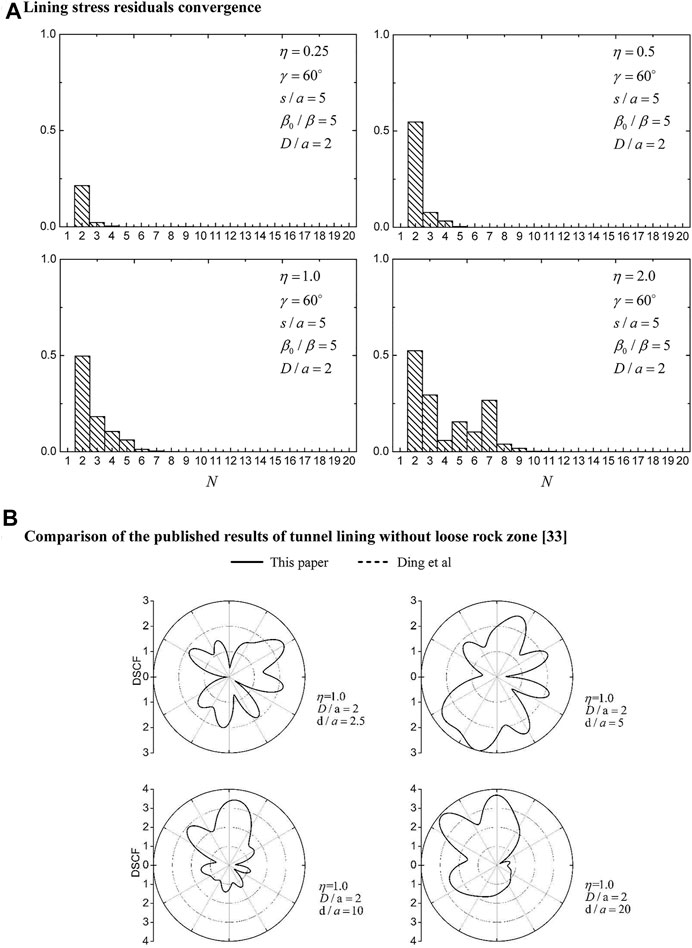
FIGURE 2. Model verification.
Comparison With the Published Results
Taking the surrounding loose rock of four layers as an example, Figure 2B shows the comparison between our results and the published results [32] (tunnel lining without loose rock zone) when
Results and Analysis
Figure 3 and Figure 4 demonstrate the results of the circumferential DSCF of the lining outer surface under different lining burial depths D/a = 2 and 5. The calculation parameters are as follows. For the lining, the shear wave velocity is β0 = 2000 m/s, Poisson’s ratio is ν0 = 0.2, and mass density ρ0 = 2,500 kg/m3; for the half-space, the shear wave velocity is β = 3,000 m/s, Poisson’s ratio is ν = 0.25, and mass density ρ = 2,750 kg/m3. The surrounding loose rock zone is assumed to be divided into four layers, and the properties of the loose rock zone are discussed in three cases as follows:
Case 1: β1 = 1800 m/s, β2 = 2100 m/s, β3 = 2400 m/s, β4 = 2700 m/s.
Case 2: β1 = 2200 m/s, β2 = 2400 m/s, β3 = 2600 m/s, β4 = 2800 m/s.
Case 3: β1 = 3000 m/s, β2 = 3000 m/s, β3 = 3000 m/s, β4 = 3000 m/s.
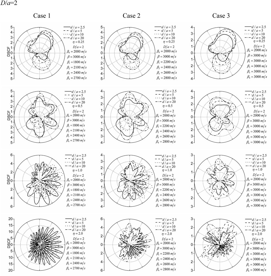
FIGURE 3. DSCF of the lining outer surface for the lining burial depth D/a = 2. Different lines (solid, dash, dot, and dash-dot lines), respectively, correspond to the wave source–lining distances d/a = 2.5, 5, 10, and 20. Rows 1–4 correspond to the dimensionless frequencies of the incident cylindrical SH-wave η = 0.25, 0.5, 1.0, and 2.0. Columns 1–3 correspond to the three cases.
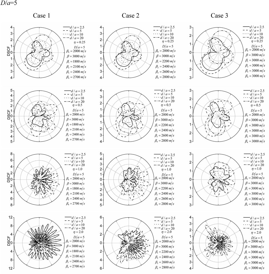
FIGURE 4. The same as Figure 3 but for the lining burial depth D/a = 5.
Case 1 represents a large degree of surrounding rock loosening around the lining, Case 2 represents a moderate degree of surrounding rock loosening, and Case 3 corresponds to no surrounding rock loosening.
The DSCF of the lining outer surface at different incident frequencies (η = 0.25, 0.5, 1.0, and 2.0) is shown in Figure 3 and Figure 4. It can be found that the amplitude of the DSCF changes gently along the circumference of the lining when the incident wave has a relatively lower frequency (η = 0.25). With the increase of the frequency of the incident wave, the amplitudes of the DSCF change dramatically along the lining circumference. This indicates that, with the increase of incident wave frequency, the refraction and scattering of incident waves in the lining and surrounding loose rock zone are intensified, which leads to the intensification of dynamic stress concentration on the outer surface of the lining.
By comparing and analyzing the DSCF amplitude under different wave source–lining distances (d/a = 2.5, 5, 10, and 20), it can be found that the distance (d/a) between the wave source and the lining has a significant influence on the DSCF. Particularly, an interesting phenomenon can be observed, that is, with the increase of the distance between the wave source and the cavity, the DSCF gradually increases, which is obviously different from that of the plane SH-wave. The reasons for this significant difference can be explained as follows. In the case of cylindrical SH-wave incidence, the denominator (stress amplitude generated by the incident cylindrical SH-wave in the free-field) in the normalization formula (Eq. 34) of the DSCF is attenuated. However, for the incident plane SH-wave, the denominator (stress amplitude caused by the plane SH-wave in the free-field) is constant.
The lining buried depth (D/a) also has a significant effect on the DSCF. It can be seen from Figure 3 and Figure 4 that when the lining buried depth is larger (D/a), the DSCF of the lining outer surface decreases to a certain extent, and the distribution of the DSCF changes dramatically. This shows that the ground surface has an important influence on the DSCF. At the same time, it can be seen that when the lining buried depth of the lining is large, the influence of a low-frequency wave is larger and that of a high-frequency wave is relatively small due to the large distance between the lining and the ground surface, which is particularly noteworthy.
The three surrounding rock case analyses include the case of no loosening of surrounding rock (Case 3). Currently, the dynamic stress concentration factor (DSCF) is relatively small, that is, the stress concentration degree is smaller than the result of the surrounding loosening rock case. In the other two cases, the surrounding rock stiffness changes linearly, and the DSCF changes greatly, indicating that the dynamic stress concentration is more obvious.
Conclusion
In this paper, the closed-form series solution of cylindrical SH-wave scattering by surrounding rock in a uniform half-space is obtained by using the wave function expansion method. Considering that blasting will inevitably loosen the surrounding rock around the tunnel lining in practical engineering, we analyze the influence of the frequency of the incident cylindrical SH-wave, the distance between the wave source and the lining, the lining buried depth, and the properties of the surrounding loose rock zone on the dynamic stress concentration of the tunnel lining, based on this series solution. The conclusions and findings are as follows:
1) Generally speaking, the incident wave with high frequency always makes the dynamic stress concentration of the tunnel lining obvious. The variation of the dynamic stress concentration factor (DSCF) curve of the lining outer surface is complex and violent, and the distribution is not uniform.
2) With the increase of the distance between the wave source and the tunnel, the stress around the tunnel lining decreases, but the dynamic stress concentration factor around the tunnel lining does not decrease significantly but occasionally increases. This is because in the calculation formula of the normalized dynamic stress concentration factor, the denominator decreases faster than the hoop stress of the lining.
3) In general, the amplitude of hoop stress in the tunnel lining decreases with the increase of lining buried depth. This is enough to show that the ground surface has a great influence on the stress concentration of the tunnel lining.
4) When other conditions are the same, the stress concentration of the surrounding loose rock zone is more obvious than that without loose rock zone. When the property of the surrounding rock (namely, shear wave velocity) changes more, the amplitude of the stress concentration factor is larger, that is, the stress concentration is more significant.
Data Availability Statement
The raw data supporting the conclusions of this article will be made available by the authors, without undue reservation.
Author Contributions
LJ and ZZ conceptualized the study. HS and LJ performed mathematical derivation and ran the computer program. LJ validated the results, wrote the original draft, and reviewed and edited the paper. SW curated the data. All authors read and agreed to publish this manuscript.
Funding
This work was supported by the National Natural Science Foundation of China (Grant Nos. 51808290, U2039208, and 41902282).
Conflict of Interest
The authors declare that the research was conducted in the absence of any commercial or financial relationships that could be construed as a potential conflict of interest.
Publisher’s Note
All claims expressed in this article are solely those of the authors and do not necessarily represent those of their affiliated organizations, or those of the publisher, the editors, and the reviewers. Any product that may be evaluated in this article, or claim that may be made by its manufacturer, is not guaranteed or endorsed by the publisher.
References
1. Trifunac MD. Scattering of Plane SH Wave by a Semi-cylindrical canyon. Earthquake Eng Struct Dyn (1973) 1:267–81. doi:10.1002/eqe.4290010307
2. Trifunac MD. Surface Motion of a Semi-cylindrical Alluvial valley for Incident Plane SH Waves. Bull Seismology Soc America (1971) 61:1755–70. doi:10.1785/bssa0610061755
3. Lee VW, Trifunac MD. Response of Tunnels to Incident SH-Waves. J Engrg Mech Div.ASCE (1979) 105(4):643–59. doi:10.1061/jmcea3.0002511
4. Zhang N, Chen X, Gao Y, Dai D. Analytical Solution to Scattering of SH Waves by a Circular Lined Tunnel Embedded in a Semi-circular Alluvial valley in an Elastic Half-Space. Tunnelling Underground Space Tech (2020) 106:103615. doi:10.1016/j.tust.2020.103615
5. Tsaur DH. Exact Scattering and Diffraction of Anti-plane Shear Waves by a Vertical Edge Crack. Geophys J Int (2010) 181(3):1655–64. doi:10.1111/j.1365-246x.2010.04577.x
6. Gao Y, Zhang N, Li D, Liu H, Cai Y, Wu Y. Effects of Topographic Amplification Induced by a U-Shaped canyon on Seismic Waves. Bull Seismological Soc America (2012) 102(4):1748–63. doi:10.1785/0120110306
7. Zhang N, Gao Y, Cai Y, Li D, Wu Y. Scattering of SH Waves Induced by a Non-symmetrical V-Shaped canyon. Geophys J Int (2012) 191(1):243–56. doi:10.1111/j.1365-246x.2012.05604.x
8. Jin L, Liang J. 2D Dynamic Structure-canyon-structure Interaction for the Buildings along the Urban River-canyon I: Incident SH-Waves in Homogenous Half-Space. J Earthquake Eng (2020) 1–19. doi:10.1080/13632469.2020.1785587
9. Jin L, Tang G, Liang J. Dynamic Soil-Structure-Equipment Interaction (I): Closed-form Analytical Solution for Incident Plane SH Wave Based on Rigid Foundation Model. J Earthquake Eng (2019) 1–17. doi:10.1080/13632469.2019.1633972
10. Jin L, Zhou W, Liang J, Huang Y. Dynamic Soil-Structure-Equipment Interaction (II): Closed-form Analytical Solution for Incident Plane SH-Wave Based on Flexible Foundation Model. J Earthquake Eng (2020) 1–26. doi:10.1080/13632469.2020.1840458
11. Lee VW, Liu W-Y. Two-dimensional Scattering and Diffraction of P- and SV-Waves Around a Semi-circular canyon in an Elastic Half-Space: an Analytic Solution via a Stress-free Wave Function. Soil Dyn Earthquake Eng (2014) 63(63):110–9. doi:10.1016/j.soildyn.2014.02.005
12. Lee VW, Zhu G. A Note on Three-Dimensional Scattering and Diffraction by a Hemispherical canyon-I: Vertically Incident Plane P-Wave. Soil Dyn Earthquake Eng (2014) 61-62(2):197–211. doi:10.1016/j.soildyn.2014.02.010
13. Lan H, Zhang Z. Three-dimensional Wave-Field Simulation in Heterogeneous Transversely Isotropic Medium with Irregular Free Surface. Bull Seismological Soc America (2011) 101(3):1354–70. doi:10.1785/0120100194
14. Zhang W, Chen X. Traction Image Method for Irregular Free Surface Boundaries in Finite Difference Seismic Wave Simulation. Geophys J Int (2006) 167(1):337–53. doi:10.1111/j.1365-246x.2006.03113.x
15. Zhou H, Chen X. A New Approach to Simulate Scattering of SH Waves by an Irregular Topography. Geophys J Int (2006) 164(2):449–59. doi:10.1111/j.1365-246x.2005.02670.x
16. Liang J, Liu Z. Diffraction of Plane P Waves by a canyon of Arbitrary Shape in Poroelastic Half-Space (I): Formulation. Earthq Sci (2009) 22(3):215–22. doi:10.1007/s11589-009-0215-y
17. Wong HL. Effect of Surface Topography on the Diffraction of P, SV, and Rayleigh Waves. Bull Seismology Soc America (1982) 72(4):1167–83.
18. Chen J-T, Chen P-Y, Chen C-T. Surface Motion of Multiple Alluvial Valleys for Incident Plane Sh-Waves by Using a Semi-analytical Approach. Soil Dyn Earthquake Eng (2008) 28(1):58–72. doi:10.1016/j.soildyn.2007.04.001
19. Lee VW, Wu X. Application of the Weighted Residual Method to Diffraction by 2-D Canyons of Arbitrary Shape: I. Incident SH Waves. Soil Dyn Earthquake Eng (1994) 13(5):355–64. doi:10.1016/0267-7261(94)90026-4
20. Lee VW, Brandow HP. Weighted Residual Method for Diffraction of Plane P-Waves in a 2D Elastic Half-Space Revisited: on an Almost Circular Arbitrary-Shaped canyon. J Earthquakes (2015) 2015:1–21. doi:10.1155/2015/543128
21. Lee VW, Wu X. Application of the Weighted Residual Method to Diffraction by 2-D Canyons of Arbitrary Shape: II. Incident P, SV and Rayleigh Waves. Soil Dyn Earthquake Eng (1994) 13(5):365–75. doi:10.1016/0267-7261(94)90027-2
22. Luco JE, Wong HL, De Barros FCP. Three-dimensional Response of a Cylindrical canyon in a Layered Half-Space. Earthquake Engng Struct Dyn (1990) 19:799–817. doi:10.1002/eqe.4290190603
23. Sanchez-Sesma FJ, Campillo M. Diffraction of P, SV, and Rayleigh Waves by Topographic Features: a Boundary Integral Formulation. Bull Seismology Soc America (1991) 81(6):2234–53.
24. Vogt RF, Wolf JP, Bachmann H. Wave Scattering by a canyon of Arbitrary Shape in a Layered Half-Space. Earthquake Engng Struct Dyn (1988) 16:803–12. doi:10.1002/eqe.4290160603
25. Kawase H. Time-domain Response of a Semi-circular canyon for Incident SV, P, and Rayleigh Waves Calculated by the Discrete Wavenumber Boundary Element Method. Bull Seismology Soc America (1988) 78(4):1415–37. doi:10.1785/bssa0780041415
26. Liang JW, You HB, Lee VW. Scattering of SV Waves by a canyon in a Fluid-Saturated, Poroelastic Layered Half-Space, Modeled Using the Indirect Boundary Element Method. Soil Dyn Earthquake Eng (2006) 26(7):611–25. doi:10.1016/j.soildyn.2006.01.012
27. Ba Z, Yin X. Wave Scattering of Complex Local Site in a Layered Half-Space by Using a Multidomain IBEM: Incident Plane SH Waves. Geophys J Int (2016) 205:1382–405. doi:10.1093/gji/ggw090
28. Ba Z, Lee VW, Liang J, Yan Y. Scattering of Plane qP- and qSV-Waves by a canyon in a Multi-Layered Transversely Isotropic Half-Space. Soil Dyn Earthquake Eng (2017) 98:120–40. doi:10.1016/j.soildyn.2017.04.005
29. Ba Z, Fu Z, Liu Z, Sang Q. A 2.5D IBEM to Investigate the 3D Seismic Response of 2D Topographies in a Multi-Layered Transversely Isotropic Half-Space. Eng Anal Boundary Elem (2020) 113:382–401. doi:10.1016/j.enganabound.2020.01.019
30. Sanchez-Sesma FJ, Palencia VJ, Luzon F. Estimation of Local Site Effects during Earthquakes: an Overview. ISET J Earthquake Tech (2002) 39:167–93.
31. Liu G, Chen H, Liu D, Khoo BC. Surface Motion of a Half-Space with Triangular and Semicircular hills under Incident SH Waves. Bull Seismological Soc America (2010) 100(3):1306–19. doi:10.1785/0120090273
32. Liang JW, Ding M, Du J. Diffraction of Cylindrical SH Waves Around Circular Lined Cavity: Analytical Solution. J Earthquake Eng Eng Vibration (2013) 33(1):1–7.
33. Li Y. Scattering of Cylindrical SH Waves by Underground, Circular Cavity. Dissertation. Tianjin: Tianjin University (2004). (in Chinese).
34. Zhang M. Scattering of Cylindrical SH Waves by Underground Circular Inclusion and Lined Tunnels. Dissertation. Tianjin: Tianjin University (2007). (in Chinese).
35. Xu Y, Liang JW, Liu ZX. Diffraction of Rayleigh Waves Around a Circular Cavity in Poro-Elastic Half-Space. Rock Soil Mech (2017) 38(8):2412–24. (in Chinese).
36. Jin L, Liang J. Dynamic Soil-Structure Interaction with a Flexible Foundation Embedded in a Half-Space: Closed-form Analytical Solution for Incident Plane SH Waves. J Earthquake Eng (2019) 25:1565–89. doi:10.1080/13632469.2019.1586802
37. Abramowitz M, Stegun IA. Handbook of Mathematical Functions with Formulas, Graphs, and Mathematical Tables. New York: Dover (1972).
38. Trifunac MD. Dynamic Interaction of a Shear wall with the Soil for Incident Plane SH Waves. Bull Seismology Soc America (1972) 62:62–83. doi:10.1785/bssa0620010063
39. Bhatti M, Lu D. Analytical Study of the Head-On Collision Process between Hydroelastic Solitary Waves in the Presence of a Uniform Current. Symmetry (2019) 11(3):333. doi:10.3390/sym11030333
Keywords: Underground tunnel, Lining, SH-wave, Analytic solution, Wave function expansion method
Citation: Jin L, Sun H, Wang S and Zhou Z (2021) A Series Solution for 2D Scattering of Cylindrical SH-Waves by Surrounding Loose Rock Zone of Underground Tunnel Lining. Front. Phys. 9:772823. doi: 10.3389/fphy.2021.772823
Received: 08 September 2021; Accepted: 28 September 2021;
Published: 15 November 2021.
Edited by:
Qingxiang Meng, Hohai University, ChinaReviewed by:
Muhammad Mubashir Bhatti, Shandong University of Science and Technology, ChinaZhang Ji, East China Jiaotong University, China
Copyright © 2021 Jin, Sun, Wang and Zhou. This is an open-access article distributed under the terms of the Creative Commons Attribution License (CC BY). The use, distribution or reproduction in other forums is permitted, provided the original author(s) and the copyright owner(s) are credited and that the original publication in this journal is cited, in accordance with accepted academic practice. No use, distribution or reproduction is permitted which does not comply with these terms.
*Correspondence: Hongyang Sun, dGp1MjA3QDE2My5jb20=