 W. Trickey
  V. N. Goncharov 1,2
- 1Laboratory for Laser Energetics, University of Rochester, Rochester, NY, United States
- 2Mechanical Engineering Department, University of Rochester, Rochester, NY, United States
The dynamic-shell target is a new class of design for inertial confinement fusion (ICF). These targets address some of the target fabrication challenges prevalent in current ICF targets and take advantage of advances in manufacturing technologies. This study first examines how the dynamic-shell design can be used to control the density of the central region and therefore convergence ratio, thus expanding the design space for ICF. Additionally, the concern of low-mode perturbation growth is considered. A new class of high-performing beam configurations, based on icosahedral polyhedra and charged-particle simulations is proposed. These configurations achieve low levels of irradiation nonuniformity through selection of beam shapes that suppress the dominant symmetrical mode.
1 Introduction
A novel inertial confinement fusion (ICF) “dynamic-shell” target design was recently proposed by V. Goncharov et al. [1]. This new generation of target aims to address a number of challenging issues with the current cryogenic, solid DT shell capsule targets. The standard approach in ICF aims to achieve gain by igniting a small portion of low density fuel in a central hot-spot, triggering a burn wave that will propagate through a surrounding, high-density fuel shell [2]. Such targets are composed of a cryogenic, solid DT shell filled with DT gas at the equilibrium vapor pressure. These targets present a number of challenges, including the production of a uniform ice layer that can be affected by engineering features (fill tubes, stalks, characterization windows, etc.) [3–5]. By contrast, the dynamic-shell target uses a liquid DT sphere encased in a wetted-DT foam. A high-density shell is then formed dynamically in-flight via a series of laser pulses that compress the target, allow it to rebound, then decelerate the expanding plasma, forming a shock that develops into the shell. The liquid DT, foam shells are intrinsically much more uniform, do not require a gas fill tube and do not have a gas shell interface, making them an attractive choice of target for inertial fusion energy (IFE) applications [6].
Figure 1 outlines a dynamic-shell target design. The laser profile consists of a number of pickets that send a series of shocks into the target, controlling the formation of the dynamic-shell. In this case, the pulse consists of a series of pickets but it should be noted that long periods of relatively low power can be used [1]. Pickets are expected to be more robust to nonuniformity growth. Mass density profiles at key times in the dynamic-shell formation are shown in Figure 1. In the initial compression phase (0–50 ns) the target is accelerated inward and converges in the center at ∼55 ns. The target subsequently rebounds and begins to expand outward; this allows for a low-density central region to form. From then on, the pickets raise the ablation pressure in the outer regions and begin to counteract the expansion of the target. At 280 ns the ablation pressure becomes sufficient to reverse the flow, launching an inward-traveling shock and forming a high-density shell. At this point the target can be imploded and ignited in the same manner as a traditional ICF target, either through central hot-spot ignition or shock ignition [7]. For the target shown in Figure 1, 0.25 MJ of the total 1.3 MJ pulse energy was contained in the pickets.
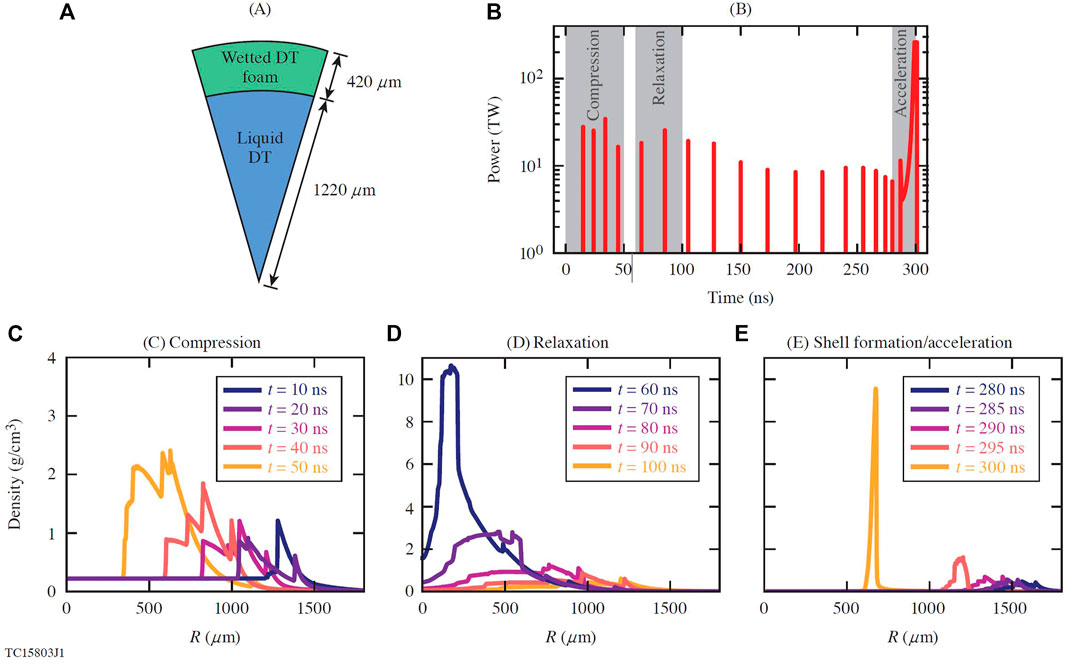
FIGURE 1. (A) A radial slice of the liquid deuterium DT-wetted foam target. (B) Time profile of the laser power, the highlighted regions correspond to the mass density profiles in the plots below. Mass density profiles taken at key times from LILAC simulations, that show (C) compression, (D) relaxation and (E) formation of the dynamic-shell.
It should be noted that the here we only consider the dynamic shell target in a direct-drive configuration [8] where the lasers are shone directly onto the capsule surface. In indirect-drive [9], the lasers are shone onto the inner surface of a high-Z casing (termed a hohlraum) creating a bath of X-rays which is then used as a drive source. Complex pulse shapes such as those employed for the dynamic shell are incredibly challenging to model in indirect-drive [10, 11], so currently we limit the scope of the dynamic shell design to direct-drive only.
The energy, power and shaping requirements of the dynamic shell pulses are all within the limits of available laser technology. However, current ICF-relevant laser systems (e.g., the National Ignition Facility [12]) only have a limited total pulse length of ≤35 ns. Ignition targets with pulses of hundreds of nanoseconds will require a new class of laser technology, such as the StarDriver™ described in Ref. [13].
In this work, it is shown how the dynamic-shell target can control the density of the central region of the target. Additionally we also summarize a study on potential laser beam configurations in order to minimize detrimental low-mode pressure perturbations.
2 Density Control of the Central Region
Shell convergence ratio (CR) in a conventional design with a cryogenic DT shell is controlled mainly by the implosion velocity Vimp and shell adiabat α defined as the ratio of shell pressure to the Fermi pressure at shell density, α = P/PF,
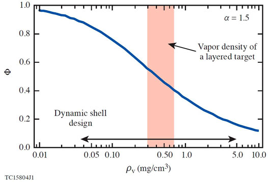
FIGURE 2. The expanded design space for the dynamic-shell compared to a standard layered target. The Φ term on the y-axis is directly proportional to the convergence ratio.
Figure 3 shows two different pulse shapes used to create a dynamic-shell. The longer pulse allows for an extended period of expansion before forming the dynamic-shell. As previously discussed, the additional expansion time should result in a lower central density. Simulations of these two laser pulses were carried out with the 1-D radiation-hydrodynamic code LILAC [16]. In each case the target was a 1220 μm-thick DT-liquid capsule with a 420 μm-thick DT-wetted foam shell. Figure 3 shows the mass density profile of the target for the long- and short-pulse designs at 208 and 295 ns, respectively. For each of the laser pulses the shell has a similar width and density profile. However, for the long-pulse, the additional expansion resulted in a central density of 0.1 mg/cm3 compared to the shorter pulse, which has a central density of 0.8 mg/cm3. Although both target designs ignite with the gain near 100, the hot-spot formation histories are quite different. The effect of reduced density in the central region of the dynamically formed shell on Rayleigh-Taylor instability during shell deceleration will be addressed in future publications.
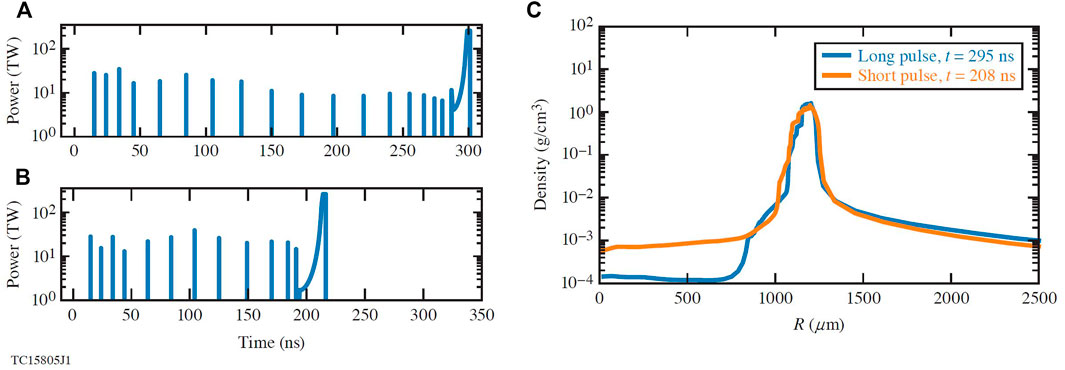
FIGURE 3. (A,B) A comparison between a short and long dynamic-shell laser pulse. (C) Mass density profiles taken from the LILAC simulations.
3 Low-Mode Perturbation Mitigation
A key concern for the dynamic-shell design is the potential growth of low-mode (ℓ⩽ 20) instabilities. The long pulse lengths involved in the dynamic-shell target give opportunity for low-mode perturbations to grow. For this reason, it is important to choose a beam configuration that minimizes any potential nonuniformity in the laser irradiation profile. Here we employ a technique developed by Murakami et al. [17–19], to investigate optimum beam configurations for the dynamic-shell design. Each beam origin is modeled as a charged-particle fixed to the surface of a sphere. In Ref. [18], the conjecture is that a configuration in which the total Coulomb potential of all particles is minimized produces the optimum beam configuration. This configuration is found via a numeric simulation where the particles are allowed to repel and move along the sphere surface. Historically, this problem is referred to as the Thomson problem, for which there exists a large body of previous work [20–22]. This study employs a method similar to that of Ref. [18]. NB (where NB is the number of beams) particles are distributed randomly on the surface of a sphere and allowed to repel each other through a Coulomb-like force with a friction-like term,
The constants A and B can be modified over the course of the simulation in order to achieve rapid convergence. Convergence was defined as the point where a time step changed the Coulomb potential Ep, by no more than 10–11, where the potential is given by
Once a beam configuration has been determined, an analytic model is used to evaluate σrms, the root-mean-square (rms) nonuniformity. The analytic model was devised by Skupsky et al [23]. and extended by Murakami et al. [18]. The model is based on the following expression for the nonuniformity
The an coefficients are contributions from laser spot profile and are calculated from Ia(θ), the irradiation absorption as a function of polar angle and Pn, the Legendre polynomials. In this case, the irradiation absorption is given by [24].
where η is the absorption efficiency and c and n are super-Gaussian parameters defined by
Configurations were found using the charged-particle technique for 6 ≤ NB ≥ 192 (even numbers only).
With the assumption that σsys = 0 and η = 0.95, the σrms was evaluated for each configuration for a number of super-Gaussian beam parameters using Eqs 3–6; the results are displayed in Figure 4. At ∼50–70 beams the reduction in rms begins to plateau and scales as
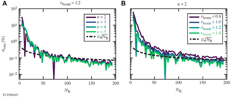
FIGURE 4. Plots of how the rms nonuniformity scales with beam number for several different Gaussian beam parameters. Note rbeam = 1.2 and n = 2 were chosen due to their high performance (see Figure 8). (A) Fixed rbeam = 1.2 with varying n. (B) Fixed n = 2 with varying rbeam.
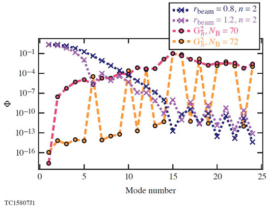
FIGURE 5. A plot of the values of Gn and
Geodesic icosahedra are a class of polyhedra formed via subdivision of the faces of an icosahedron and projecting the resulting vertices onto the surface of a sphere. A list of vertex coordinates for such shapes were taken from Ref. [25] and used as angular coordinates for beam configurations. The NB = 32, 42, 72, 92, 122, 132, 172 and 192 configurations are formed from the vertices of geometric icosahedra, whereas the NB = 60, 80, 140 and 180 configurations used the coordinates of the face centers. The geometric factors and subsequent rms nonuniformities were calculated for these configurations using the parameters rbeam = 0.8, 1.2 and n = 2. The results are displayed in Figure 6. It can be seen that, for the beam configuration (rbeam = 1.2, n = 2) that suppresses the ℓ = 6 mode, the symmetric configurations perform better than the corresponding charged-particle configurations. Conversely it is also possible for certain beam parameters to amplify the ℓ = 6 mode resulting in a higher σrms; this can be seen for smaller beams with rbeam = 0.8, n = 2. It is noted that the authors suspect there is a similar class of octahedrally symmetric configurations that can be constructed from geodesic octohedra. Such configurations will have a significant ℓ = 4 mode which can similarly be suppressed with appropriate beam parameters. This is likely the origin of the high performing NB = 48 beam configuration observed by Murakami et al. [18].
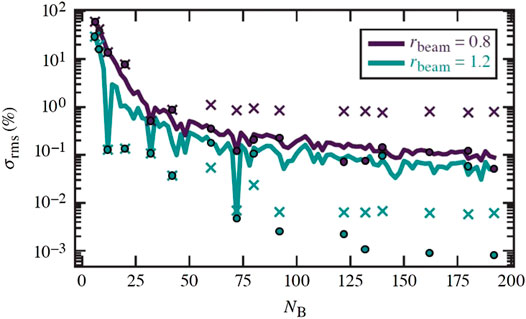
FIGURE 6. Comparison of the rms nonuniformity between symmetric and charged-particle configurations. The solid line shows the results from charged-particle configurations. The x’s are from configurations based on geometric icosahedra. The circles are from charged-particle configurations that were initialized with geometric icosahedral positions.
At
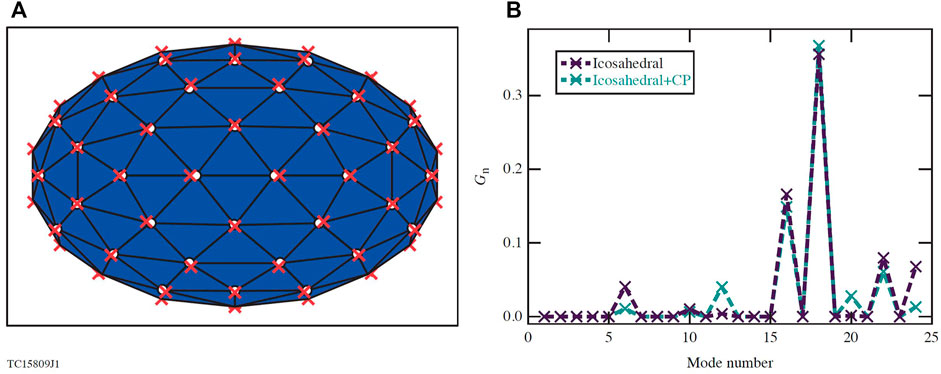
FIGURE 7. (A) 3D plot of two 92 beam configurations. The white circles and blue surface show the icosahedral configuration, the red x’s are where the points move under a charged-particle simulation initialized with the icosahedral positions. (B) The geometric factor values for the two configurations shown in (A).
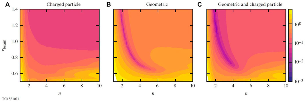
FIGURE 8. Contour plots for how σrms varies with the beam parameters rbeam and n. All plots are for 92 beam configurations, (A) charged-particle configuration with a random initialization (B) geodesic icosahedral configuration (C) charged-particle initialized with geodesic icosahedral configuration.
Up to this point, imperfections in the laser and target have been neglected. Such effects can be included the model via the
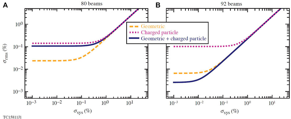
FIGURE 9. Plots that show how the rms nonuniformity scales with the system rms. In each plot the scaling is shown for charged-particle configurations (dotted line), geodesic icosahedral configurations (dashed line) and charged-particle configurations with geodesic icosahedral initial setups (solid line). The 80-beam (A) configuration is face-centered whereas the 92 beam configuration (B) is vertex-centered.
The results from this study suggest that, if system rms (e.g., target offset, beam mispointing, power imbalance etc.) can be kept below 1–2%, the optimized icosahedral configurations will perform better than the charged particle ones. This is a reasonable goal; the value of 1% is commonly used as an upper limit on acceptable nonuniformity [8]. However, it is worth noting that if nonuniformity did go above this 1% limit, a symmetric configuration would be equally as optimal as a charged-particle configuration with an equal beam number.
Current investigations have been limited to the use of an analytic physics model. Further work will be done in 2-& 3-D simulations in order to evaluate the conclusions drawn so far, also it may be interesting to consider if any further improvements can be made to beam shapes.
4 Conclusion
Dynamic-shell ICF targets represent a new class of designs that will not experience the manufacturing issues present in the standard cryogenic shell targets. In this work, an additional benefit was demonstrated in that, by controlling the central density through laser pulse shape, the convergence ratio can be modified, expanding the ICF target design space. Further to that, uniform beam irradiation was investigated in order to mitigate the low-mode perturbations to which the dynamic-shell implosion may be susceptible. A new class of beam configuration formed through charged-particle simulations of geodesic icosahedral vertices were discovered. These configurations were shown to perform better than previously proposed charged-particle configurations by more than an order of magnitude. However, to achieve high performance, specific super-Gaussian beam parameters must be used, while keeping other nonuniformities below 1%.
Data Availability Statement
The raw data supporting the conclusions of this article will be made available by the authors, without undue reservation.
Author Contributions
WT carried out all simulations and analysis directly supervised by VG. All other Authors offered support and guidance for the work.
Funding
Funding was provided by the ARPA-E BETHE Grant No. DE-FOA-0002212. This material is based upon work supported by the Department of Energy National Nuclear Security Administration under Award Number DE-NA0003856, the University of Rochester, and the New York State Energy Research and Development Authority.
Author Disclaimer
The support of DOE does not constitute an endorsement by DOE of the views expressed in this paper. This report was prepared as an account of work sponsored by an agency of the U.S. Government. Neither the U.S. Government nor any agency thereof, nor any of their employees, makes any warranty, express or implied, or assumes any legal liability or responsibility for the accuracy, completeness, or usefulness of any information, apparatus, product, or process disclosed, or represents that its use would not infringe privately owned rights. Reference herein to any specific commercial product, process, or service by trade name, trademark, manufacturer, or otherwise does not necessarily constitute or imply its endorsement, recommendation, or favoring by the U.S. Government or any agency thereof. The views and opinions of authors expressed herein do not necessarily state or reflect those of the U.S. Government or any agency thereof.
Conflict of Interest
The authors declare that the research was conducted in the absence of any commercial or financial relationships that could be construed as a potential conflict of interest.
Publisher’s Note
All claims expressed in this article are solely those of the authors and do not necessarily represent those of their affiliated organizations, or those of the publisher, the editors and the reviewers. Any product that may be evaluated in this article, or claim that may be made by its manufacturer, is not guaranteed or endorsed by the publisher.
References
1. Goncharov VN, Igumenshchev IV, Harding DR, Morse SFB, Hu SX, Radha PB, et al. .Novel Hot-Spot Ignition Designs for Inertial Confinement Fusion with Liquid-Deuterium-Tritium Spheres. Phys Rev Lett (2020) 125:065001. doi:10.1103/PhysRevLett.125.065001
2. Atzeni S, Meyer-ter Vehn J. The Physics of Inertial Fusion: Beam Plasma Interaction, Hydrodynamics, Hot Dense Matter, Vol. 125. Oxford: OUP Oxford (2004).
3. Lindl J, Landen O, Edwards J, Moses E, Adams J, Amendt PA, et al. .Review of the National Ignition Campaign 2009-2012. Phys Plasmas (2014) 21:020501. doi:10.1063/1.4865400
4. Weber CR, Casey DT, Clark DS, Hammel BA, MacPhee A, Milovich J, et al. .Improving ICF Implosion Performance with Alternative Capsule Supports. Phys Plasmas (2017) 24:056302. doi:10.1063/1.4977536
5. Rinderknecht HG, Casey DT, Hatarik R, Bionta RM, Macgowan BJ, Patel P, et al. .Azimuthal Drive Asymmetry in Inertial Confinement Fusion Implosions on the National Ignition Facility. Phys Rev Lett (2020) 124:145002. doi:10.1103/physrevlett.124.145002
6. Sacks RA, Darling DH. Direct Drive Cryogenic ICF Capsules Employing D-T Wetted Foam. Nucl Fusion (1987) 27:447–52. doi:10.1088/0029-5515/27/3/009
7. Betti R, Zhou CD, Anderson KS, Perkins LJ, Theobald W, Solodov AA. Shock Ignition of Thermonuclear Fuel with High Areal Density. Phys Rev Lett (2007) 98(15):155001. doi:10.1103/physrevlett.98.155001
8. Craxton RS, Anderson KS, Boehly TR, Goncharov VN, Harding DR, Knauer JP, et al. .Direct-Drive Inertial Confinement Fusion: A review. Physics of Plasmas (2015) 22(11):110501. doi:10.1063/1.4934714
9. Lindl J. Development of the Indirect‐drive Approach to Inertial Confinement Fusion and the Target Physics Basis for Ignition and Gain. Phys Plasmas (1995) 2:3933–4024. doi:10.1063/1.871025
10. Kirkwood RK, Moody JD, Kline J, Dewald E, Glenzer S, Divol L, et al. .A Review of Laser-Plasma Interaction Physics of Indirect-Drive Fusion. Plasma Phys Control Fusion (2013) 55:103001. doi:10.1088/0741-3335/55/10/103001
11. Moody JD, Callahan DA, Hinkel DE, Amendt PA, Baker KL, Bradley D, et al. .Progress in Hohlraum Physics for the National Ignition Facility. Phys Plasmas (2014) 21:056317. doi:10.1063/1.4876966
12. Spaeth ML, Manes KR, Bowers M, Celliers P, Nicola J-MD, Nicola PD, et al. .National Ignition Facility Laser System Performance. Fusion Sci Techn (2016) 69:366–94. doi:10.13182/fst15-136
13. Eimerl D, Campbell M, Krupke W, Zweiback J, Kruer W, Marozas J, et al. .StarDriver: A Flexible Laser Driver for Inertial Confinement Fusion and High Energy Density Physics. J Fusion Energ (2014) 33:476–488. doi:10.1007/s10894-014-9697-2
14. Olson RE, Leeper RJ, Yi SA, Kline JL, Zylstra AB, Peterson RR, et al. .Wetted Foam Liquid Fuel ICF Target Experiments. J Phys Conf Ser (2016) 717:012042. doi:10.1088/1742-6596/717/1/012042
15. Paddock RW, Martin H, Ruskov RT, Scott RHH, Garbett W, Haines BM, et al. .One-dimensional Hydrodynamic Simulations of Low Convergence Ratio Direct-Drive Inertial Confinement Fusion Implosions. Phil Trans R Soc A (2021) 379(2189):20200224. doi:10.1098/rsta.2020.0224
16. Delettrez J, Epstein R, Richardson MC, Jaanimagi PA, Henke BL. Effect of Laser Illumination Nonuniformity on the Analysis of Time-Resolved X-ray Measurements in Uv Spherical Transport Experiments. Phys Rev A (1987) 36:3926–34. doi:10.1103/physreva.36.3926
17. Murakami M, Nishihara K, Azechi H. Irradiation Nonuniformity Due to Imperfections of Laser Beams. J Appl Phys (1993) 74:802–8. doi:10.1063/1.354869
18. Murakami M, Sarukura N, Azechi H, Temporal M, Schmitt AJ. Optimization of Irradiation Configuration in Laser Fusion Utilizing Self-Organizing Electrodynamic System. Phys Plasmas (2010) 17(8):082702. doi:10.1063/1.3467497
19. Murakami M, Nishi D. Optimization of Laser Illumination Configuration for Directly Driven Inertial Confinement Fusion. Matter Radiat Extremes (2017) 2:55–68. doi:10.1016/j.mre.2016.12.002
20. Thomson JJ. XXIV. On the Structure of the Atom: an Investigation of the Stability and Periods of Oscillation of a Number of Corpuscles Arranged at Equal Intervals Around the Circumference of a circle; with Application of the Results to the Theory of Atomic Structure. Lond Edinb Dublin Phil Mag J Sci (1904) 7(39):237–65. doi:10.1080/14786440409463107
21. Erber T, Hockney GM. Equilibrium Configurations of N Equal Charges on a Sphere. J Phys A Math Gen (1991) 24(23):L1369–L1377. doi:10.1088/0305-4470/24/23/008
22. Morris JR, Deaven DM, Ho KM. Genetic-algorithm Energy Minimization for point Charges on a Sphere. Phys Rev B (1996) 53:R1740–R1743. doi:10.1103/physrevb.53.r1740
23. Skupsky S, Short RW, Kessler T, Craxton RS, Letzring S, Soures JM. Improved Laser‐beam Uniformity Using the Angular Dispersion of Frequency‐modulated Light. J Appl Phys (1989) 66:3456–62. doi:10.1063/1.344101
25. Mccooey DI. Visual Polyhedra (2015). Available at: http://dmccooey.com/polyhedra/
Keywords: inertial confinement fusion, dynamic shell, density, convergence ratio, beam geometry, irradiation uniformity
Citation: Trickey W, Goncharov VN, Igumenshchev IV, Shvydky A, Collins TJB and Campbell EM (2021) Central Density and Low-Mode Perturbation Control of Inertial Confinement Fusion Dynamic-Shell Targets. Front. Phys. 9:784258. doi: 10.3389/fphy.2021.784258
Received: 27 September 2021; Accepted: 30 November 2021;
Published: 22 December 2021.
Edited by:
Daniele Margarone, Queen’s University Belfast, United KingdomReviewed by:
Dimitri Batani, Université de Bordeaux, FranceLeonida A. Gizzi, Consiglio Nazionale Delle Ricerche, Italy
Copyright © 2021 Trickey , Goncharov , Igumenshchev , Shvydky , Collins and Campbell . This is an open-access article distributed under the terms of the Creative Commons Attribution License (CC BY). The use, distribution or reproduction in other forums is permitted, provided the original author(s) and the copyright owner(s) are credited and that the original publication in this journal is cited, in accordance with accepted academic practice. No use, distribution or reproduction is permitted which does not comply with these terms.
*Correspondence: W. Trickey , d3RyaUBsbGUucm9jaGVzdGVyLmVkdQ==