 Shuangshuang Yuan
 Qizhi Zhu2
 Wanlu Zhang
 Jin Zhang
 Lunyang Zhao
- 1Electrical Engineering College, Nanjing Vocational University of Industry Technology, Nanjing, China
- 2Key Laboratory of Ministry of Education for Geomechanics and Embankment Engineering, Hohai University, Nanjing, China
- 3Guangdong Key Laboratory of Integrated Agro-environmental Pollution Control and Management, Guangdong Engineering Center of Non-point Source Pollution Prevention Technology, Guangdong Institute of Eco-environment Science and Technology, Guangzhou, China
- 4South China Research Institute on Geotechnical Engineering, School of Civil Engineering and Transportation, South China University of Technology, Guangzhou, China
A micromechanical anisotropic damage model with a non-associated plastic flow rule is developed for describing the true triaxial behaviors of brittle rocks. We combine the Eshelby’s solution to the inclusion problem with the framework of irreversible thermodynamics. The main dissipative mechanisms of inelastic deformation due to the frictional sliding and damage by microcrack propagation are strongly coupled to each other. A Coulomb-type friction criterion is formulated in terms of the local stress applied onto the microcracks as the yielding function. The back-stress term contained in this local stress plays a critical role in describing the material’s hardening/softening behaviors. With a non-associated flow rule, a potential function is involved. Some analytical analysis of the non-associated micromechanical anisotropic damage model are conducted, which are useful for the model parameters calibration. The proposed model is used to simulate the laboratory tests on Westerly granite under true triaxial stresses. Comparing the numerical simulation results provided by the models with associated/non-associated plastic flow rule and experimental results, it is clear that the proposed non-associated model gives a better prediction than the previous associated model.
1 Introduction
Constitutive model and simulation of the mechanical behaviors of heterogeneous rocks under general stress conditions have a great significance on the investigation of the safety and stability of rock engineering. Since host rocks in underground engineering are most often in a true triaxial stress state, researchers have conducted many true triaxial compression tests [1–7]. In 1967, [8] firstly developed an experimental apparatus that combined torsion and triaxial compression. It provided general triaxial stress states but did not produce the conditions of homogeneous triaxial stress. Then [9, 10] implemented homogeneous triaxial stress using triaxial cells. [11] used Mogi’s cell design to fabricate a cell to test larger sample sizes. After that, [4,12] did a series of experiments on different rocks using the true triaxial loading system at the University of Wisconsin. Recently, Feng et al. [13,14] designed a novel Mogi type true triaxial testing apparatus and utilized it to obtain complete stress-strain curves of many hard Rocks.
In terms of constitutive model, a number of researchers [15–18] have developed numerical models or used commercial software to study the failure processes of rocks under polyaxial stress conditions. [19] established a damage softening statistical constitutive model with the assumption that the rock micro-unit failure obeys the Weibull random distribution under the true triaxial stress state. Through linear fitting method and elastoplastic mechanical analysis, [20] built a true triaxial constitutive model of coal rock under horizontal stress loading. At present, it is very common to use the isotropic assumption in most constitutive models. However, geomaterials, such as rocks and concrete, display stress-induced anisotropy in their mechanical properties. Considering it difficult in modeling the anisotropy, few researchers have established anisotropic theoretical models with physical meaning for simulating the true triaxial stress-strain curve of rocks.
This paper will extend the previous work [21] for modeling the true triaxial mechanical behavior of hard rocks. The micromechanical anisotropic damage model [21] has been established with an associated plastic flow rule. However, a large number of experimental and theoretical results show that a non-associated plastic flow rule must be adopted to more accurately describe the inelastic deformation of rocks. To this end, a micromechanical anisotropic damage model with a non-associated plastic flow rule will be developed, which will be used to simulate laboratory tests on Westerly granite under true triaxial stresses.
The following tensorial product notations are used throughout this paper:
2 Formulation of Non-assocaited Micromechanical Anisotropic Damamge Model
In this section, a micromechanical anisotropic damage model with a non-associated plastic flow rule for brittle rocks is formulated. A representative elementary volume (REV), defined by a geometrical domain Ω and its boundary surface ∂Ω, is shown in Figure 1. The relevant REV as a matrix-inclusion system for microcracked rocks is composed of an isotropic linearly elastic matrix with a stiffness tensor
where
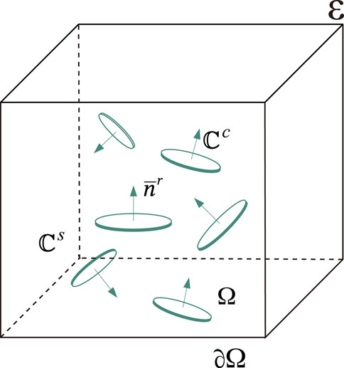
FIGURE 1. Representative elementary volume (REV) of brittle rocks.
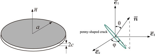
FIGURE 2. A penny-shaped microcrack and its orientation angles.
2.1 Strain Decomposition
The domain occupied by a family of microcracks (with the same unit normal vector
where
The displacement discontinuity is characterized by two variables:
i) a scalar, β, representing the microcrack opening degree
ii) a sliding vector,
with
The inelastic deformation due to the displacement discontinuities [23] generated by a family of penny-shaped microcracks of normal
All the microcracks in the REV are discontinuities dispersed in the solid matrix. Accordingly, the total strain of REV is decomposed into two terms: an elastic part ɛe, which is the result of the deformation of the matrix phase and an inelastic part ɛp, which is due to the existence of microcracks.
where ɛp can be expressed by the simple sum of each family’s microcrack contribution
and ϱr is the weight of the rth family of microcracks.
2.2 Effective Elastic Properties and Free Energy
The Mori-Tanaka scheme [24] is taken into account within the standard linear homogenization framework, and the effective stiffness tensor
where
with
Since microcrack propagation gives rise to the degradation of the material stiffness, it is possible to define an alternative macroscopic damage variable ωr according to the relative variation of the Young’s modulus [27,28].
where
Theoretical studies [29,30] have shown that
Along with the previous work [21], for any opening/closure combination of the microcrack families, the free energy takes the general form
with
2.3 Damage Criterion
The damage criterion is a function of the thermodynamic force Fd,r associated with the internal damage variable dr, which can be derived by applying the standard differentiation of the macroscopic free energy W.
In regards to the damage evolution law, a strain energy release rate-based damage criterion is largely adopted for all microcrack families:
where
where κr = dr/dc is defined as a dimensionless parameter. Physically, dc represents the critical damage values corresponding to the peak stress, and
When the damage criterion Eq. 15 is satisfied, the damage evolution rate is determined by using the normality rule:
with λd,r being a non-negative damage multiplier for the rth family of microcracks.
2.4 Friction Criterion With Non-associated Flow Rule
When microcracks are open, there is no friction effect between the microcracks. Therefore, we only consider the friction criterion for closed microcracks. The generalized Coulomb criterion is used as the yielding function to describe the friction sliding occurring along the closed microcracks. Given the macroscopic free energy in Eq. 13, the thermodynamic force associated with the local inelastic strain ϵp, denoted by the local stress σc, is deduced by the standard derivation of W with respect to ϵp:
where
At the microscopic scale, the Coulomb criterion is determined by the normal and tangential components represented by
where cf is the friction coefficient of the microcracks, which is related to the asperity of microcracks’ surfaces [32].
For most brittle rocks, a large number of true triaxial tests indicated that the associated plastic flow rule was generally not suitable to describe the volumetric deformation. Therefore, we propose the following plastic potential function. To be consistent, this function is similar to the friction criterion:
where cv is termed as the current volumetric dilation coefficient. When cv = cf, the friction function is completely consistent with the potential function. At this time, the model adopts the associated plastic flow rule.
In the classical plasticity theory, the evolution rate of the local inelastic strain εp is given by the normality rule:
where λp,r is a non-negative friction multiplier for the rth family of microcracks and Dn,r is served as the plastic flow direction by a second-order tensor,
3 Model Parameters Calibration Method
The proposed model only contains six material constants or model parameters, each having a clear physical meaning. Using a series of conventional triaxial compression tests under different confining pressures, the model parameters can be determined. Before discussing the model parameters calibration, some analytical analyses of the non-associated micromechanical anisotropic damage model under conventional triaxial compression are first conducted.
3.1 Analytical Expression of Peak Stress and Crack Damage Stress
Under the loading path of conventional triaxial compression, the local friction criterion (19) for the critical plane with θ = θc which satisfies the condition
with
It is possible to define the plastic multiplier in such a way that Λp = ∫λp, then
By substituting Eq. 24 into Eq. 23, we can derive the following expression by defining
By combining Eqs. 14, 21, 22, the damage criterion (15) is reformulated as
with
For the critical sliding plane, the friction criterion can be expressed in terms of ξ1 and ξ2:
Finally, the analytical expression of peak stress can be derived as:
On the other hand, in the volume strain-deviatoric stress curve, the volume strain will reverse with the increase of deviatoric stress, and this point is called the volume compressibility dilatancy (C/D) transition point. A series of researches [33,34] have shown that the crack damage stress σcd is defined as the volume compressibility dilatancy (C/D) transition stress. Inspired by the strength prediction, we assume that there also exists a critical damage value dcd corresponding to σcd. On the basis of Eq. 29, the following crack damage stress can be expressed as:
According to the classical elastic-plastic theory, the volume strain ɛv is the sum of elastic volume strain
By ignoring the volumetric strain generated by the confining pressure and the inelastic strain generated by the initial crack closure and using Eqs. 21, 31, the volumetric strain generated in the axial loading phase can be rewritten into the following form:
Inserting Eq. 27 into the above formula, the volumetric strain ϵv becomes:
The increment of volume strain is equal to 0 at the volume C/D transition point, i.e.
with
3.2 Model Parameters Calibration
With the above analytical analysis at hand, we here discuss the model parameters calibration procedure as follows:
• The means of Young’s modulus Es and Poisson’s ratio νs of can be determined using the linear part of the stress-strain curves.
• The friction coefficient cf can be obtained by comparing strength criterion Eq. 29 with the peak stress envelope.
• Parameter dc has no influence on peak strength of materials and is related to the deformation at peak strength state and the post-peak stress-strain curve. With the increase of dc, the deformation at peak strength is increasing [21].
• The parameter cv can be identified by solving Eq.30, 34. In this process, the intermediate variable ϖ must first be determined by comparing the peak stress envelope with the crack damage stress envelope.
• The critical damage resistance
If the associated flow rule is adopted to describe the inelastic strain of the material, there are only 5 parameters in the model. The parameters calibration method above is still available.
4 Model Application on Westerly Granite
In this section, the proposed model is applied to modeling the mechanical behavior of Westerly granite subjected to true triaxial compression loading. Firstly conventional triaxial compression test results on Westerly granite conducted by [4] are adopted to determine the model parameters. With the parameters calibration method in Section 4, we obtained the associated/non-associated micromechanical anisotropic damage models parameters and listed as follows:
• Associated micromechanical anisotropic damage model parameters: Es = 68000MPa, νs = 0.21, dc = 18, cf = 1.27,
• Non-associated micromechanical anisotropic damage model parameters: Es = 68000MPa, νs = 0.21, dc = 18, cf = 1.27, cv = 0.45,
4.1 Numberical Simulations
With the above parameters and using the plastic-damage decoupled correction (PDDC) numerical algorithm [35], numerical simulations of assocaited/non-associated micromechanical anisotropic damage models on true triaxial comoression tests of Westerly granite are conducted.
Figure 3 shows the curves of the deviator stress
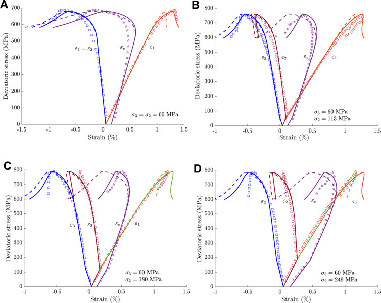
FIGURE 3. Comparisons of the models’ predictions with the experimental data for the true triaxial compression tests on Westerly granite (The dotted lines are the associated model’s results and the solid lines are the non-associated model’s results). (A) intermediate principal stress σ2 = 60 MPa, (B) intermediate principal stress σ2 = 113 MPa, (C) intermediate principal stress σ2 = 180 MPa, and (D) intermediate principal stress σ2 = 249 MPa.
Figure 4 shows the damage density distribution with the different intermediate principal stress values. These 2D coupled plans
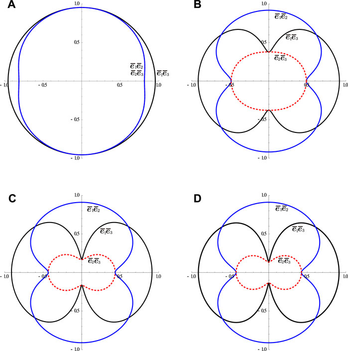
FIGURE 4. Damage distribution at the peak stresses in different intermediate principal stress compression test (A) intermediate principal stress σ2 = 60 MPa, (B) intermediate principal stress σ2 = 113 MPa, (C) intermediate principal stress σ2 = 180 MPa, and (D) intermediate principal stress σ2 = 249 MPa.
5 Conclusion
A new micromechanical anisotropic damage model with a non-associated plastic flow rule has been developed for describing the true triaxial compression behaviors for brittle rocks. Unlike the previous models, the potential function plays a critical role in the integration of the model. Importantly, the non-associated flow rule works quite well to describe the inelastic deformations in both the axial and lateral directions. We have discussed the model parameters calibration procedure based on some analytical analysis of the proposed model under conventional triaxial compression loading. The model has been finally applied to simulate true triaxial stress-strain curves of Westerly granite. One can see that a good agreement between the non-associated model’s predictions and the experimental data for under true triaxial compression loading path. Moreover, the non-associated model could provide a better description of true triaxial mechanical behaviors than that of our previous associated micromechanical anisotropic damage model [21].
It is worth noting that our proposed model only contains six parameters, each having a clear physical meaning. Each of the parameters can be easily identified from a series of conventional triaxial tests. We will present important extensions related to the time-dependent behaviors of brittle rocks under true triaxial compression in future work.
Data Availability Statement
The original contributions presented in the study are included in the article/Supplementary Material, further inquiries can be directed to the corresponding author.
Author Contributions
SY: Data curation, Formal analysis, Investigation, Methodology, Software, Validation, Writing—original draft. QZ: Conceptualization, Methodology. WZ: Software, Visualization, Writing—review and editing, Resources. JZ: Supervision, Writing—review and editing. LZ: Supervision, Writing—review and editing.
Funding
This work has been jointly supported by the Natural Science Foundation of Nanjing Vocational University of Industry Technology (YK20-02-12).
Conflict of Interest
The authors declare that the research was conducted in the absence of any commercial or financial relationships that could be construed as a potential conflict of interest.
Publisher’s Note
All claims expressed in this article are solely those of the authors and do not necessarily represent those of their affiliated organizations, or those of the publisher, the editors and the reviewers. Any product that may be evaluated in this article, or claim that may be made by its manufacturer, is not guaranteed or endorsed by the publisher.
References
1. Mogi K. Effect of the Intermediate Principal Stress on Rock Failure. J Geophys Res (1967) 72:5117–31. doi:10.1029/jz072i020p05117
2. Wawersik WR, Carlson LW, Holcomb DJ, Williams RJ. New Method for True-Triaxial Rock Testing. Int J Rock Mech Mining Sci (1997) 34:330. doi:10.1016/s1365-1609(97)00049-x
3. Chang C, Haimson B. True Triaxial Strength and Deformability of the German continental Deep Drilling Program (Ktb) Deep Hole Amphibolite. J Geophys Res (2000) 105:18999–9013. doi:10.1029/2000jb900184
4. Haimson B, Chang C. A New True Triaxial Cell for Testing Mechanical Properties of Rock, and its Use to Determine Rock Strength and Deformability of westerly Granite. Int J Rock Mech Mining Sci (2000) 37:285–96. doi:10.1016/s1365-1609(99)00106-9
5. Liu HD, Cao J. Test and Study on Influence of Intermediate Main Stress to Characteristic of Rock Mechanics (2008) 30:56–60+80.
6. Xiang TB, Feng XT, Chen BR, Jiang Q, Zhang CQ. Rock Failure Mechanism and True Triaxial Experimental Study of Specimens with Single Structure Plane under Three-Dimensional Stress. Rock Soil Mech (2009) 30:2908–16. doi:10.16285/j.rsm.2009.10.053
7. Feng X-T, Zhang X, Kong R, Wang G. A Novel Mogi Type True Triaxial Testing Apparatus and its Use to Obtain Complete Stress-Strain Curves of Hard Rocks. Rock Mech Rock Eng (2015) 49:1649–62. doi:10.1007/s00603-015-0875-y
8. Handin J, Heard HC, Magouirk JN. Effects of the Intermediate Principal Stress on the Failure of limestone, Dolomite, and Glass at Different Temperatures and Strain Rates. J Geophys Res Atmospheres (1967) 72:320–2. doi:10.1029/jz072i002p00611
9. Hojem J, Cook N. The Design and Constructon of a Triaxial and Polyaxial Cell for Testing Rock Specimens. South Africa Mech.Engr. (1968) 18:57–61.
10. Mogi K. Fracture and Flow of Rocks under High Triaxial Compression. J Geophys Res (1971) 76:1255–69. doi:10.1029/jb076i005p01255
11. Takahashi M, Koide H, Takahashi M. Effect of the Intermediate Principal Stress on Strength and Deformation Behavior of Sedimentary Rocks at the Depth Shallower Than 200m. In: International Symposium on Rock at Great Depth; 1989 August 28–39; PAU (1989).
12. Haimson BC, Chang C. True Triaxial Strength of the Ktb Amphibolite under Borehole wall Conditions and its Use to Estimate the Maximum Horizontal In Situ Stress. J Geophys Res Atmospheres (2002) 107:ETG 15–1–ETG 15–4. doi:10.1029/2001jb000647
13. Feng X-T, Zhang X, Kong R, Wang G. A Novel Mogi Type True Triaxial Testing Apparatus and its Use to Obtain Complete Stress-Strain Curves of Hard Rocks. Rock Mech Rock Eng (2016) 49:1649–62. doi:10.1007/s00603-015-0875-y
14. Zhao J, Feng X-T, Zhang X-W, Zhang Y, Zhou Y-Y, Yang C-X. Brittle-ductile Transition and Failure Mechanism of Jinping marble under True Triaxial Compression. Eng Geology (2018) 232:160–70. doi:10.1016/j.enggeo.2017.11.008
15. Cai M. Influence of Intermediate Principal Stress on Rock Fracturing and Strength Near Excavation Boundaries-Insight from Numerical Modeling. Int J Rock Mech Mining Sci (2008) 45:763–72. doi:10.1016/j.ijrmms.2007.07.026
16. Lu S, Xiao-Chun LI. Analysis of End Friction Effect in True Triaxial Test. Rock Soil Mech (2009) 30:1159–64. doi:10.16285/j.rsm.2009.04.057
17. Hudson JA, Tang C. Rock Failure Mechanisms: Explained and Illustrated. London: Taylor & Francis (2010).
18. Pan P-Z, Feng X-T, Hudson JA. The Influence of the Intermediate Principal Stress on Rock Failure Behaviour: A Numerical Study. Eng Geol (2012) 124:109–18. doi:10.1016/j.enggeo.2011.10.008
19. Zhang H, Xie X, Zhang M, Yang G. Damage Constitutive Model of Rock under the True Triaxial Confinement State. Mech Eng (2015) 37:75–8.
20. Cui C, Zhang L, Li H, Wang D. Three axis Failure Criterion and Constitutive Model of Coal Rock under Horizontal Stress Loading. In: International Conference on Oil and Gas Field Exploration and Development; 2018 September 18–20; Xi'an, China (2018).
21. Zhu QZ, Shao JF. A Refined Micromechanical Damage-Friction Model with Strength Prediction for Rock-like Materials under Compression. Int J Sol Structures (2015) 60-61:75–83. doi:10.1016/j.ijsolstr.2015.02.005
22. Budiansky B, O'connell RJ. Elastic Moduli of a Cracked Solid. Int J Sol Struct (1976) 12:81–97. doi:10.1016/0020-7683(76)90044-5
23. Horii H, Nemat-Nasser S. Overall Moduli of Solids with Microcracks: Load-Induced Anisotropy. J Mech Phys Sol (1983) 31:155–71. doi:10.1016/0022-5096(83)90048-0
24. Mori T, Tanaka K. Average Stress in Matrix and Average Elastic Energy of Materials with Misfitting Inclusions. Acta Metallurgica (1973) 21:571–4. doi:10.1016/0001-6160(73)90064-3
25. Kachanov M. Effective Elastic Properties of Cracked Solids: Critical Review of Some Basic Concepts. Appl Mech Rev (1992) 45:304–35. doi:10.1115/1.3119761
26. Zhu Q-Z, Yuan S-S, Shao J-f. Bridging Meso- and Microscopic Anisotropic Unilateral Damage Formulations for Microcracked Solids. Comptes Rendus Mécanique (2017) 345:281–92. doi:10.1016/j.crme.2017.02.003
27. Lemaitre J, Dufailly J. Damage Measurements. Eng Fracture Mech (1987) 28:643–61. doi:10.1016/0013-7944(87)90059-2
28. Murakami S. Continuum Damage Mechanics: A Continuum Mechanics Approach to the Analysis of Damage and Fracture, Vol. 41. London, New York: Springer Ebooks (2012). 4731–4755. doi:10.1007/978-94-007-2666-6
29. Ladeveze P, Ladeveze P. Sur une theorie de l’endommagement anisotrope (1983). Laboratoire de Mechanique et Technologie, Cachan. Technical Report 34.
30. He Q-C, Curnier A. A More Fundamental Approach to Damaged Elastic Stress-Strain Relations. Int J Sol Struct (1995) 32:1433–57. doi:10.1016/0020-7683(94)00183-w
31. Zhu Qz. Strength Prediction of Dry and Saturated Brittle Rocks by Unilateral Damage-Friction Coupling Analyses. Comput Geotechn (2016) 73:16–23. doi:10.1016/j.compgeo.2015.11.015
32. Zhao L-Y, Lai Y-M, Shao J-F, Zhang W-L, Zhu Q-Z, Niu F-J. Friction-damage Coupled Models and Macroscopic Strength Criteria for Ice-Saturated Frozen silt with Crack Asperity Variation by a Micromechanical Approach. Eng Geol (2021) 294:106405. doi:10.1016/j.enggeo.2021.106405
33. Martin CD, Chandler NA. The progressive fracture of lac du bonnet granite. Int J Rock Mech Mining Sci Geomech Abstr (1994) 31:643–59. doi:10.1016/0148-9062(94)90005-1
34. Xue L, Qin S, Sun Q, Wang Y, Lee LM, Li W. A Study on Crack Damage Stress Thresholds of Different Rock Types Based on Uniaxial Compression Tests. Rock Mech Rock Eng (2014) 47:1183–95. doi:10.1007/s00603-013-0479-3
Keywords: micromechanics, anisotropy, non-associated flow rule, damage, true triaxial
Citation: Yuan S, Zhu Q, Zhang W, Zhang J and Zhao L (2021) A Micromechanical Anisotropic Damage Model for Brittle Rocks With Non-Associated Plastic Flow Rule Under True Triaxial Compressive Stresses. Front. Phys. 9:808375. doi: 10.3389/fphy.2021.808375
Received: 03 November 2021; Accepted: 17 November 2021;
Published: 21 December 2021.
Edited by:
Wanqing Shen, Université de Lille, FranceReviewed by:
Zihao Zhao, Shenyang Jianzhu University, ChinaBingyi Li, Suzhou University of Science and Technology, China
Copyright © 2021 Yuan, Zhu, Zhang, Zhang and Zhao. This is an open-access article distributed under the terms of the Creative Commons Attribution License (CC BY). The use, distribution or reproduction in other forums is permitted, provided the original author(s) and the copyright owner(s) are credited and that the original publication in this journal is cited, in accordance with accepted academic practice. No use, distribution or reproduction is permitted which does not comply with these terms.
*Correspondence: Wanlu Zhang, d2wtemhhbmdAZm94bWFpbC5jb20=