 Yaya Zhang
 Jie Zhao
 Dayong Wang
 Kunlun Li
 Lu Rong
 Yunxin Wang
- 1College of Physics and Optoelectronics, Faculty of Science, Beijing University of Technology, Beijing, China
- 2Beijing Engineering Research Center of Precision Measurement Technology and Instruments, Beijing, China
Continuous-wave terahertz digital holography (TDH) is a full-field lensless phase imaging approach usually with the coherent THz laser. It has the potential to be applied to nondestructive testing. In order to simplify the reconstruction and utilize the THz radiation with higher efficiency, a full-field reflective lensless Fourier-transform TDH (RLF-TDH) configuration is proposed with oblique illumination mode based on 2.52 THz radiation. A spherical reference beam is generated by a reflective concave mirror in order to reduce the loss of THz radiation, which is different from other configurations of the same kind. In the reconstruction process, the complex-amplitude image can be obtained by directly applying single Fourier transform to the digital hologram; thus, it is very possible to achieve real-time imaging. A tilted plane correction method is implemented to correct the anamorphism caused by the nonparallel planes between the object and recording plane. The profile information of the object can be measured from the unwrapped, aberration-free phase image. Two reflective gold-coated samples are adopted to demonstrate the validity of the RLF-TDH imaging system.
Introduction
Terahertz (THz) spectral range lies between approximately 0.1 and 10 THz. The THz band owns the unique property and broad prospects in many fields, for example, security inspection, art protection, and studies on biological samples [1]. Reflective THz imaging technology is suitable for obtaining the surface profiles of the object, for example, nondestructive testing [2], in vivo imaging of burned skin [3], and measurement of explosive compounds [4]. The reflection THz pulsed imaging can provide a broadband spectral image with both amplitude and phase information [5, 6]. However, the reflective imaging receives the signal of weak reflection from the nonuniformity surface of the object. Thus, most such imaging systems suffer from the problems of relatively high optical complexity and lack of high-power sources. Continuous-wave (CW) THz reflective imaging approaches are blooming based on the laser with high output power. The amplitude distribution of an object can be obtained by using a reflective CW THz confocal microscopy with high resolution [7], but the imaging speed is limited by the mechanical scanning rate, and the pinhole in this approach leads to much loss of THz radiation. Another method that needs to scan is self-mixing, which needs quantum cascade laser as the transceivers [8]. Besides, the surface profile of object can be also measured by THz heterodyne profilometry based on an independent local oscillator reference signal [9]. The above scanning imaging approaches are limited by the time-consuming recording process and mechanical inertia. With the maturity development of THz array detectors, such as microbolometer and pyroelectric detector, CW THz full-field phase imaging has become a promising imaging method. THz ptychography can retrieve the complex amplitude distribution of the object from a set of diffraction patterns originating of sample’s partially overlapped illumination areas [10]. This method cannot realize recording in real time presently.
Reflective THz digital holography (TDH) is a full-field phase imaging method. It can obtain the amplitude and phase information of the object from the numerical reconstruction of a recorded digital hologram and acquire the surface profile and depth information of the sample. Different from the transmission TDH, it has been used for imaging of the sample hidden behind the material, which is transparent to THz wave [11, 12]. Reflection TDH can achieve high-resolution imaging by recording holograms with double parallel recording planes; the inherent “twin image” problem is eliminated by using iterative phase restoration algorithm [13], but it needs to record several holograms. Fresnel off-axis reflection TDH imaging can yield the complex amplitude of the object by recording single-frame hologram, whereas the reconstruction algorithm includes Fresnel or angular spectrum propagation, which requires accurate reconstruction distance and multiple Fourier transform [14, 15]. In lensless Fourier-transform digital holographic imaging configuration, the spherical reference beam is brought to focus on the object plane. Usually, a pinhole or lens is introduced to lead to a spherical reference beam in other spectral regions. This imaging layout is simple and compact; meanwhile, the numerical reconstruction only needs one Fourier transform of the digital hologram, which is conducive to real-time imaging [16]. This method has been carried out in a lot of imaging researches in visible light, X-ray, and ultraviolet bands [17–21]. However, when the method is expanded to THz band, because the categories of the available elements are relatively few, and the loss of the energy is high, the configuration is better to avoid applying the transmission elements or use less elements and is better to be compact and has high utilization rate of the energy.
In this article, we investigate a full-field reflective lensless Fourier-transform THz digital holographic (RLF-TDH) imaging method with oblique illumination. In the proposed geometry, a concave mirror is used to form a spherical reference beam. The experimental setup is built based on a 2.52-THz laser and a pyroelectric array detector. A single Fourier transform is performed to yield the complex amplitude of the object wavefront at the image plane in almost real time. A tilted plane correction method is implemented to correct the deformation caused by the nonparallel between the object and detector planes. Two gold-coated objects with Chinese character are used to demonstrate the ability for the surface profiling.
Methodology
Lensless Fourier-Transform Digital Holographic Interferometry
The schematic of the RLF-TDH setup is shown in Figure 1, where x0-y0 and x-y are the coordinate systems as the object plane and hologram recording plane, respectively. The object is illuminated by a plane wave in the positive z direction. In the RLF-TDH configuration, the object and the point source of the reference beam must be kept in the same plane.
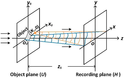
FIGURE 1. Schematic of the coordinate system of object plane and recording plane of lensless Fourier-transform hologram.
Assuming that the object is illuminated by a normally incident plane wave with unit amplitude, the complex distribution of the object beam in the object plane is denoted by
where
in which (xr, 0) is the coordinate of the point source of the spherical reference beam. The object beam and the reference beam interfere at the recording plane to produce a hologram. The intensity of hologram can be expressed as
where ∗ indicates a complex conjugation. The first two terms contain the DC components associated with the zero-order term, and the third and fourth terms correspond to the interference terms containing the complex-value information of object. To suppress the DC term and twin image effect, Fourier spectrum analysis approach is utilized to separate the term supporting the object. The fourth term in Eq. 3 can be extracted as
The reconstructed object wave field O (x′,y′) can be finally reconstructed as
where x′-y′ is the coordinate of the reconstructed image plane, and FT−1{} denotes the inverse Fourier transformation. The relationships between the recording plane and the reconstructed image plane are
The reconstructed phase distribution of the object
where the operators Re and Im denote the real and imaginary parts of a complex function, respectively. The calculated phase distribution from Eq. 6 is wrapped within the range [–π, π), which is coincident with the output range of the arctangent function. Then, a least-square phase unwrapping algorithm [23] is used to obtain the unwrapped phase. The method of least-square surface fitting is finally applied to eliminate the aberrations and to access the practical phase distribution of the object [24]. The above reconstructed algorithm, involving only a single Fourier transform, is fast enough compared with other existing methods such as the Fresnel method [11, 12, 14, 15] and phase shifting method [18], and so on, which involve several Fourier transforms or complex multiplications and slow down the reconstruction process. For reflective object (in air n = 1), the surface topography
where θ is half of the angle between the illumination and the observation directions in the case of inclined illumination, which is coincident with our proposed configuration.
The Correction of Tilted Illumination RLF-TDH
The model of the RLF-TDH via tilted illumination is established and shown in Figure 2. The incident wave plane is not parallel to the object plane, and the object plane is not parallel to the recording plane. In this case, the reconstruction results are incorrect based on the traditional diffraction propagation theory between parallel planes. The correction of tilted illumination needs to be adopted.
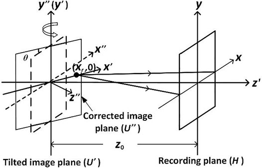
FIGURE 2. Schematic of the correction to the tilted reconstructed image under tilted illumination.
It can be seen from the reconstruction principle in the previous section that the complex optical field can be obtained by a single inverse Fourier transform of the recorded hologram I (x, y) on the tilted reconstructed image plane U′ (x′, y′), which is parallel to the detector plane at a distance z0. In tilted illumination scheme, first, the Fourier spectrum of U′ (x′, y′) is calculated as
The Fourier spectral distribution of the reconstructed image U' (x', y') is given by
where (
where
where
Thus, the corrected complex amplitude of the field is written as
When the calculation for fast Fourier transform is processed, the sampling points need to be on an equidistant grid. Thus, the complex value of the spectrum
Experimental Setup
The schematic of the experimental setup of the RLF-TDH is depicted in Figure 3. In the configuration, an optically pumped far-infrared gas laser (295 FIR, Edinburgh Instruments, 2.52 THz) was used as a coherent light source. The laser emitted a CW THz beam at a wavelength of 118.83 µm with the maximum output power of 500 mW. The beam size was expanded to 22 mm by a pair of gold-coated off-axis parabolic mirrors (PM1 and PM2). The collimated beam was divided into two parts using a HRFZ-Si beam splitter, whose splitting ratio at 2.52 THz was 54% for transmission and 46% for reflection. The reflected beam was reflected by a gold-coated concave mirror with a focal length of 100 mm for constituting a diverging spherical reference beam. The gold-coated concave mirror used here could offer more than 99% reflection of the THz wave; thus, the loss of the THz radiation can be significantly minimized compared by using a pinhole or lens. The transmitted beam was reflected by the surface of the object with an incidence angle of approximate 45° measured by a protractor. The sample was mounted on a precision rotary stage in order to capture the direct reflected intensity by using the camera. The reference point source and the object were located at the same plane. The tilted object beam interfered with the spherical reference beam at the recording plane to form a lensless Fourier-transform hologram, which was recorded by a pyroelectric array detector (Pyrocam-IV, Ophir Spiricon), whose pixel pitch was 80 × 80 µm and featuring 320 × 320 pixels. The off-axis angle between the object beam and the spherical reference beam was approximately 38°, which enabled the zero-order term and the twin image to be separated in the Fourier spectrum domain. In this case, the spatial frequency of fringe pattern was satisfied the Nyquist criterion and avoided the risk of undersampling. The chopping frequency of the detector was 50 Hz. To enhance the signal to noise ratio of the diffraction patterns, 500 frames were recorded at each position and accumulated via Gaussian fitting [28].
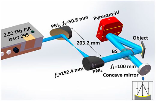
FIGURE 3. Experimental setup of RLF-TDH. BS, beam splitter; PMi, off-axis parabolic mirror.
Experimental Results and Discussion
Two different samples were measured in order to test the performance and resolution of the proposed RLF-TDH setup. The first adopted object is a gold-coated tinfoil; a Chinese character “Ji” was impressed in a convex manner on its surface as shown in Figure 4A. The etching depth of the Chinese character is approximately 200 µm as measured by a vernier caliper. It was placed at a distance of 92.0 mm upstream from the detector. The theoretical lateral resolution of the imaging system is
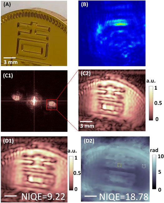
FIGURE 4. Reconstruction results of the gold-coated tinfoil sample. (A) Picture of the illuminated area of the object; (B) and (C1) are the digital hologram and reconstructed amplitude image; (C2) is the zoomed area of the +1 order in (C1); (D1) is the reconstructed amplitude map after tilted plane correction; (D2) is the reconstructed unwrapped, aberration-free and corrected phase image.
Another investigated sample is a commemorative coin made of yellow copper alloy with a diameter of 30 mm, as depicted in Figure 5A. On the surface of the coin, the main pattern is a Chinese character “He” with a regular script style, and there are many grooves, as shown in the square dashed-line regions. The depth of the Chinese character was measured by a vernier caliper as 30 μm. Figure 5B shows the digital hologram of the coin, and the period of the resulting interference fringe is approximately 5.31 lp/mm in the zoomed region. The reconstructed amplitude distribution and enlarged image of the coin are shown in Figure 5C1 and Figure 5C2, respectively. The shape aberration with the elliptic outline along the horizontal direction is caused by only a small portion of the illuminated area at the object plane and is in focus. Thus, the tilted plane correction is needed. In order to determine the angle θ accurately, the aspect ratio parameter is introduced to quantitatively evaluate the shape of sample, and the original value of the Chinese character “口” is 1.31. After tilted plane correction introduced above, the reconstructed amplitude distribution and the unwrapped, aberration-free phase distribution are shown in Figure 5D1 and Figure 5D2. It is clearly seen that the reconstructed results are stretched along the x-axis and closer to the real distributions at the object plane. At this time, the length–width ratios of the Chinese character “口” are 1.02 and 1.33 before and after the tilted plane correction, respectively, and the rotation angle and the sampling interval are calculated as 40° and 77.6 μm. In this case, Δx″ (427.04 µm) is larger than λ/(2cosθ) (77.6 μm). It verifies the feasibility of the correction of the tilted illumination approach. However, there are still some residual aberration and out-of-focus in the reconstructed results. That is because the correction of tilted illumination could work well when the tilted angle is small and the field of view is also small. Besides, the etching depth of some areas of the engraved metal samples we use is relatively large, which makes part of the illumination beam unable to be reflected to the recording plane. It results in the dark area of the reconstructed images, especially near the border of the Chinese character. Figure 5D3 and Figure 5D4 show the amplitude and phase distribution curves taken along the white dotted lines shown in Figure 5D1 and Figure 5D2. In order to verify the measurement effective of the proposed method, the white and yellow lines are drawn in Figure 5D2, representing the “He” stroke and background, whose phase values are 3.32 and 5.17 rad, respectively. Thus, the calculated etching depth of the selected part of the Chinese character is 31.5 μm.
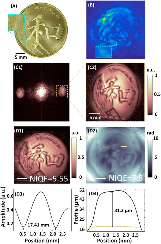
FIGURE 5. Results of the commemorative coin. (A) Photo; (B) hologram; (C1) reconstructed amplitude image; (C2) enlarged real image in (C1). (D1) and (D2) are the reconstructed amplitude and phase images after correction, respectively; (D3) and (D4) are the amplitude and thickness profiles of the cutting lines at the insets of (D1) and (D2).
Conclusion
In this article, we have implemented a reflective lensless Fourier-transform TDH (RLF-TDH) imaging configuration based on tilted illumination. The proposed method has compact configuration and high utilization rate of the energy, which is suitable for the reflective samples. Compared with other TDHs in reflection imaging methods, the spherical reference beam, generated by a concave mirror, guarantees the almost similar intensity with the object beam. It avoids the occasion that the intensity of THz radiation is weakened by a pinhole or the lens with high absorptivity, for example, polyethylene lens. At the same time, the numerical reconstruction of RLF-TDH requires only a single inverse Fourier transform. Thus, the speed of reconstruction is obviously accelerated; thus, it is very possible to achieve real-time imaging. Because of its oblique illumination geometry, a frequency spectrum coordinate transformation method is used for correcting the complex amplitude of the object wavefront at the tilted image plane. The proposed method is verified by two reflective samples. The first detected sample has a relatively rough surface than the second sample; thus, the restructured results are not as good as that of the coin. The proposed imaging configuration has great potential to open new opportunities toward applications in material characterization and dynamic nondestructive testing. Besides, this useful and emerging imaging technology can be applied to coherent diffraction imaging field in other wave bands.
Data Availability Statement
The raw data supporting the conclusion of this article will be made available by the authors, without undue reservation.
Author Contributions
JZ and DW supervised the project and funding acquisition. YZ designed and built the setup, performed experiments and wrote the draft of the manuscript. JZ, KL, LR, and YW contributed to data analysis. JZ and DW reviewed and edited of the manuscript; All authors have read and agreed to the published version of the manuscript.
Funding
The work is mainly supported by National Natural Science Foundation of China (62075001) and Science Foundation of Education Commission of Beijing (KZ202010005008). Partly supported by National Natural Science Foundation of China (62175004).
Conflict of Interest
The authors declare that the research was conducted in the absence of any commercial or financial relationships that could be construed as a potential conflict of interest.
Publisher’s Note
All claims expressed in this article are solely those of the authors and do not necessarily represent those of their affiliated organizations, or those of the publisher, the editors and the reviewers. Any product that may be evaluated in this article, or claim that may be made by its manufacturer, is not guaranteed or endorsed by the publisher.
References
1. Zhang Y, Wang C, Huai B, Wang S, Zhang Y, Wang D, et al. .Continuous-Wave THz Imaging for Biomedical Samples. Appl Sci (2021) 11:71. doi:10.3390/app11010071
2. Lee ES, Kim M, Moon K, Lee IM, Park DW, Shin JH, et al. .High-Speed and Cost-Effective Reflective Terahertz Imaging System Using a Novel 2D Beam Scanner. J Lightwave Technol (2020) 38:4237–43. doi:10.1109/JLT.2020.2988890
3. Taylor ZD, Singh RS, Culjat MO, Suen JY, Grundfest WS, Lee H, et al. .Reflective Terahertz Imaging of Porcine Skin burns. Opt Lett (2008) 33:1258–60. doi:10.1364/ol.33.001258
4. Zhong H, Redo-Sanchez A, Zhang XC. Identification and Classification of Chemicals Using Terahertz Reflective Spectroscopic Focal-Plane Imaging System. Opt Express (2006) 14:9130–41. doi:10.1364/oe.14.009130
6. Jiang Z, Xu XG, Zhang XC. Improvement of Terahertz Imaging with a Dynamic Subtraction Technique. Appl Opt (2000) 39:2982–7. doi:10.1364/ao.39.002982
7. Li Q, Zhou Y, Yang YF, Chen GH. 252 Terahertz Dual-axis Reflection Confocal Scanning Microscope. J Opt Soc Am A (2016) 33:637–41. doi:10.1364/josaa.33.000637
8. Wienold M, Hagelschuer T, Rothbart N, Schrottke L, Biermann K, Grahn HT, et al. .Real-time Terahertz Imaging through Self-Mixing in a Quantum-cascade Laser. Appl Phys Lett (2016) 109:11102–5. doi:10.1063/1.4955405
9. Löffler T, May T, am Weg C, Alcin A, Hils B, Roskos HG. Continuous-wave Terahertz Imaging with a Hybrid System. Appl Phys Lett (2007) 90:91111–3. doi:10.1063/1.2711183
10. Rong L, Tang C, Zhao Y, Tan F, Wang Y, Zhao J, et al. .Continuous-wave Terahertz Reflective Ptychography by Oblique Illumination. Opt Lett (2020) 45:4412–5. doi:10.1364/ol.400506
11. Valzania L, Zolliker P, Hack E. Topography of Hidden Objects Using THz Digital Holography with Multi-Beam Interferences. Opt Express (2017) 25:11038–47. doi:10.1364/oe.25.011038
12. Wang D, Zhao Y, Rong L, Wan M, Shi X, Wang Y, et al. .Expanding the Field-Of-View and Profile Measurement of Covered Objects in Continuous-Wave Terahertz Reflective Digital Holography. Opt Eng (2019) 58:1–023115. doi:10.1117/1.OE.58.2.023111
13. Petrov NV, Perraud JB, Chopard A, Guillet JP, Smolyanskaya OA, Mounaix P. Terahertz Phase Retrieval Imaging in Reflection. Opt Lett (2020) 45:4168–71. doi:10.1364/ol.397935
14. Locatelli M, Ravaro M, Bartalini S, Consolino L, Vitiello MS, Cicchi R, et al. .Real-time Terahertz Digital Holography with a Quantum cascade Laser. Sci Rep (2015) 5:13566. doi:10.1038/srep13566
15. Zolliker P, Hack E. THz Holography in Reflection Using a High Resolution Microbolometer Array. Opt Express (2015) 23:10957–67. doi:10.1364/oe.23.010957
16. Wagner C, Seebacher S, Osten W, Jüptner W. Digital Recording and Numerical Reconstruction of Lensless Fourier Holograms in Optical Metrology. Appl Opt (1999) 38:4812–20. doi:10.1364/ao.38.004812
17. Dong J, Jia S, Jiang C. Surface Shape Measurement by Multi-Illumination Lensless Fourier Transform Digital Holographic Interferometry. Opt Commun (2017) 402:91–6. doi:10.1016/j.optcom.2017.05.051
18. Yamagiwa M, Minamikawa T, Minamiji F, Mizuno T, Tokizane Y, Oe R, et al. .Visualization of Internal Structure and Internal Stress in Visibly Opaque Objects Using Full-Field Phase-Shifting Terahertz Digital Holography. Opt Express (2019) 27:33854–3368. doi:10.1364/oe.27.033854
19. Kumar M, Shakher C. Experimental Characterization of the Hygroscopic Properties of wood during Convective Drying Using Digital Holographic Interferometry. Appl Opt (2016) 55:960–8. doi:10.1364/ao.55.000960
20. Tadesse GK, Eschen W, Klas R, Hilbert V, Schelle D, Nathanael A, et al. .High Resolution XUV Fourier Transform Holography on a Table Top. Sci Rep (2018) 8:8677. doi:10.1038/s41598-018-27030-y
21. Guehrs E, Günther CM, Könnecke R, Pfau B, Eisebitt S. Holographic Soft X-ray Omni-Microscopy of Biological Specimens. Opt Express (2009) 17:6710–20. doi:10.1364/oe.17.006710
22. Goodman JW. Introduction to Fourier Optics. Colorado: Roberts and company publishers (2005). p. 491.
23. Pritt MD, Shipman JS. Least-squares Two-Dimensional Phase Unwrapping Using FFT's. IEEE Trans Geosci Remote Sensing (1994) 32:706–8. doi:10.1109/36.297989
24. Di J, Zhao J, Sun W, Jiang H, Yan X. Phase Aberration Compensation of Digital Holographic Microscopy Based on Least Squares Surface Fitting. Opt Commun (2009) 282:3873–7. doi:10.1016/j.optcom.2009.06.049
25. Matsushima K. Formulation of the Rotational Transformation of Wave fields and Their Application to Digital Holography. Appl Opt (2008) 47:D110–D116. doi:10.1364/ao.47.00d110
26. Matsushima K, Schimmel H, Wyrowski F. Fast Calculation Method for Optical Diffraction on Tilted Planes by Use of the Angular Spectrum of Plane Waves. J Opt Soc Am A (2003) 20:1755–62. doi:10.1364/JOSAA.20.001755
27. Kim Y-H, Kim GH, Ryu H, Chu H-Y, Hwang C-S. Exact Light Propagation between Rotated Planes Using Non-uniform Sampling and Angular Spectrum Method. Opt Commun (2015) 344:1–6. doi:10.1016/j.optcom.2015.01.029
28. Rong L, Latychevskaia T, Wang D, Zhou X, Huang H, Li Z, et al. .Terahertz In-Line Digital Holography of Dragonfly Hindwing: Amplitude and Phase Reconstruction at Enhanced Resolution by Extrapolation. Opt Express (2014) 22:17236–45. doi:10.1364/oe.22.017236
Keywords: THz digital holography, lensless fourier-transform, phase contrast imaging, reflective imaging, profile measurement
Citation: Zhang Y, Zhao J, Wang D, Li K, Rong L and Wang Y (2022) Lensless Fourier-Transform Terahertz Digital Holography for Full-Field Reflective Imaging. Front. Phys. 9:818130. doi: 10.3389/fphy.2021.818130
Received: 19 November 2021; Accepted: 15 December 2021;
Published: 02 February 2022.
Edited by:
Jianglei Di, Guangdong University of Technology, ChinaCopyright © 2022 Zhang, Zhao, Wang, Li, Rong and Wang. This is an open-access article distributed under the terms of the Creative Commons Attribution License (CC BY). The use, distribution or reproduction in other forums is permitted, provided the original author(s) and the copyright owner(s) are credited and that the original publication in this journal is cited, in accordance with accepted academic practice. No use, distribution or reproduction is permitted which does not comply with these terms.
*Correspondence: Jie Zhao, emhhb2ppZUBianV0LmVkdS5jbg==