 Bingning Jin
 Hongbo Xu
- Science and Technology on Combustion, Internal Flow and Thermo-Structure Laboratory, Northwestern Polytechnical University, Xi’an, China
Condensed phase particles (CCPs) of plume flows in solid rocket motors (SRMs) are one of the major causes of smog and other signal characteristics, which leads to attenuation of weapons guidance system signals. In order to study the dynamic combustion characteristics of the exhaust plume in a high pressure solid rocket motor with highly-aluminized propellanta digital in-line holographic (DIH) measurement system was used for identification and analysis of CCPs of exhaust plume flows in a SRM under 10 MPa pressure. During the SRM firing, the plume particles characteristic in the field of 9–11.5 cm away from the non-expanding nozzle outlet plane was measured and analyzed. Further, in order to improve the efficiency and accuracy of particle identification, a target recognition method suitable for autonomous recognition of plume particles in a complex background from digital holographic images was established. About 12,400 individual particles from two thousand holographic images were recognized, and the 3D spatial information (number and volume probability density function) and mean diameters were obtained and analyzed. The results showed that digital in-line holography measurement technology with target recognition method established in this paper can be applied well to real-time measurement of the 3D dynamic characteristics of the plume particle field anywhere outside of the nozzle outlet of an SRM with highly aluminized propellants. By identifying each reconstructed particle, the 3D spatial distribution, CCPs size distribution and velocity in the measurement area can be obtained.
Introduction
Aluminum powder has been widely used as a metal additive in solid propellants for solid rocket motors (SRMs). The addition of aluminum powder can improve the specific impulse and damping high-frequency combustion instability [1, 2]. However, the aluminum powder leads to adverse effects because of the condensed phase particles of exhaust plumes flowing in a solid rocket motor, which are primary constituents of smoke and other infrared characteristic signals [3–5]. The size and concentration of smoke particles affect the penetrating ability of various optical signals and the diffusion speed of smoke, which leads to attenuation of the signal of the weapons guidance system. Therefore, in order to suppress the plume characteristic signal of the SRM, it is necessary to investigate the characteristics of the condensed combustion products (CCPs) of the plume flow in an SRM with used a highly aluminized propellant, and so as to deeply understand the mid-infrared radiation characteristics of the plume.
A lot of experimental research has been conducted on the characteristics of CCPs in plumes, such as the mechanical collection and optical measurement method [6–11]. The traditional particle collection method can reveal the particle size distribution of the condensed phase particles; however it modifies the flow field structure and particle state, resulting in a different actual plume state. Moreover, it does not provide information about the particle size, 3D spatial distribution, and dynamic process of the particles in the plume. In contrast to the collection method, imaging techniques are useful to obtain the CCP dynamic characteristics. However, the small focal depth, high pressure, high temperature, high velocity, and strong emission intensity of the traditional optical techniques limits dynamic CCP measurement. Only a few effective plume particles can be obtained in the focal plane, preventing accurate distribution sizes of the particle in the plume unless lots of experiments are performed.
To overcome these shortcomings, the digital in-line holography technique was used for imaging CCPs in the SRM plume in this study [12–15]. In this paper, holographic in-line technology was used to measure the plume particle characteristics in the field of the non-expanding 2D nozzle outlet plane and reconstruct the holographic image, and a target recognition method suitable for autonomous recognition of plume particles in a complex background from digital holographic images was established. About tens of thousands of individual particles from two thousand holographic images were recognized, and the 3D spatial information (number and volume probability density function) and mean diameters were obtained and analyzed. These results are expected to expand the knowledge on plume particle distribution characteristics in the SRM and also could provide a diagnostic technique for studying the plume dynamic characteristics at different nozzle sections during the SRM firing.
Methods
Digital In-Line Holography System
The experimental system for the digital in-line holographic (DIH) measurement of a solid rocket plume flow field constitutes four components: an SRM, microscopic imaging system, pressure recording device, and DIH system (Figure 1). An AP/RDX/HTPB composite propellant sample containing 18% aluminum was placed at both ends of the SRM chamber and ignited by heating a wire. The nozzle without the divergent section placed at the center of the chamber. In order to ensure that the particle concentration of the plume field is not too high, the thickness of the plume field perpendicular to the laser path direction needs to be thin. Therefore, under the 10 MPa pressure condition in the SRM, the thickness of 2D nozzle throat is 2 mm, as shown in Figure 1. When the SRM fires, the product gas exhaust flow from both ends of the motor converges at the middle, passed through the convergence section, escapes from the nozzle throat, and forms a plume flowfield outside the nozzle. A pressure measuring device was used to collect the pressure data.
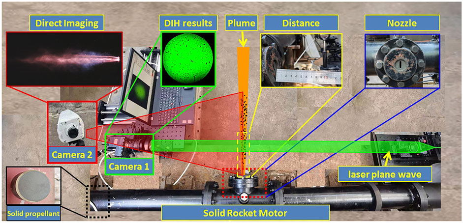
FIGURE 1. Experimental system for DIH measurement of solid rocket plume flow field.
To obtain information pertaining to the plume flow field particles, two high-speed cameras were used: Camera 1 (Micro C110) for DIH system and Camera 2 for microscopic imaging. Due to the radiation light, influence of the plume field was weak near 532 nm, the wavelength of the incoming laser light. A narrow optical bandpass 532 ± 10 nm notch filter was used to reduce the broadband emission from aluminum particles while approximately capturing the entire laser light. The typically size of particles in plumes ranges between 100–102 microns, requiring long-distance microscopic lenses to obtain the particle image. However, the high-temperature radiation from the plume field (approximately 2500 K) affects the imaging system. The position of the camera should be sufficiently far from the measurement area at approximately 1 M distance. Thus, a 0.5× (approximate) magnification system was used together with Camera 1, resulting in an actual pixel size of approximately 30 × 30 μm, which covered a large fraction of plume particles. The holographic measurement area was approximately 26 × 26 mm2, and its center was approximately 10 cm away from the nozzle outlet plane. The camera was operated at 1,000 fps, with an exposure time of 5 μs Camera 2 (EVO 640) was used to image the entire plume flow field and obtain its dynamic characteristics. Camera 2 was operated at 2000 fps at an exposure time of 1 μs When the plume particles directly escaped from the throat, without accelerated through the expansion section, the particles could slowly down. According to the measured results, the observed plume particles velocity is rang of 200–700 m/s, and there no obvious motion blurring phenomenon in the results of two cameras. The plume image results are show in Figure 2. The holographic field is higher than the central area, the upper part of the holographic field was less disturbed by the exhaust gas flow, and a large amount of diffraction information of plume particles can be obtained. However, the lower part of the holographic field of view is strongly affected by high density exhaust gas flow and the laser could not pass through it, so clear holographic information of particles could not be obtained.
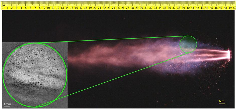
FIGURE 2. Typical image results of SRM plume field.
Numerical Reconstruction and Target Recognition Method
The DIH measurement process consists of two steps: hologram recording and reconstruction. In this study, a planar light wave travelling across the plume flow field was recorded using a CCD, which obtained the original holographic image of the plume field particle. After denoising the original holographic image, and the final holographic image was reconstructed through the angle spectrum method. When the reconstructed and imaging distances are equal, the complex light field amplitude of the object can be obtained. Based on the spatial distribution range and particle size distribution range of the plume flowfield, a sufficient z-axis depth (Δz) was set to approximately 25 μm. To obtain a locally-focused hologram at different Z-axis positions and 4,000 slices were reconstructed across a distance of approximately 0 ≤ z ≤ 100 mm from the focal plane. By using the depth-of-field extension method, all the particles in a series of plane images were focalized in a single synthesis image that is in a single-frame hologram.
To obtain all plume information during motor operation, all hologram images should be processed. The effective working time of the SRM was about 2 s, and 2000 original DIH images were obtained in the test. The depth of field range of holographic measurement method is much larger than that of the microscopic imaging method, so the number of reconstructed holographic particles is much larger, corresponding to tens of thousands of particles, and hundreds of particles respectively. Therefore, the traditional target detection method of manual identification and positioning is very time-consuming and inefficient to extract all particle information from all holograms in the whole experiment process, which greatly restricts the rapid and accurate application of holographic technology. Therefore, to improve the post-processing efficiency and accuracy of this process, this study established a target recognition method suitable for autonomous recognition of solid propellant aluminum combustion particles in a complex background from digital holographic images [16].
First, 500 effectively reconstructed holographic images were selected for plume particle labeling, and a total of 20,000 independent sample particles with particle size distribution ranging from 65 to 900 microns were labeled, forming a relatively rich plume particle information data set.
Second, the data set is divided into training, verification and test sets in a 6:2:2 ratios. Considering that the object of target recognition is a plume holographic particle, which has the characteristics of large flow, fast speed, loud noise and complex background, this paper selects the YOLO V3 model, which has good detection accuracy and detection speed in small target recognition, and as the main frame. The YOLO V3 target recognition model is trained with the data of the training set, and a training model which can effectively recognize digital holographic image particles is obtained.
Third, train the model with the training sets, and verify the trained model with verification sets. The confidence threshold was set to 0.6, and for single holographic images the prediction process was about 65 ms. In Figure 3iii the discrete single particle image shows good identification of particles (marked by the green bounding box), with an average accuracy of about 0.85. The result shows that the model training meets the needs of target detection of holographic plume particles.
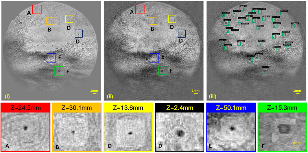
FIGURE 3. Raw, refocused holograms and target recognition of plume particles (i) Raw hologram. (ii) Refocused hologram of particles at z0 = 0. (iii) target recognition. (A–F) Refocused holograms for particles with diameters of 169, 65,103, 250,159, and 533 μm, respectively.
Finally, the model was used to detect the other unlabeled holographic images, and about 12,000 effective particles were identified. The granularity and coordinate information of all identified particles were obtained by the watershed segmentation algorithm, allowing information of all holographic plume particles in the whole experiment measurement to be obtained.
Results
Typical Digital In-Line Holographic Results
Figure 3i shows typical holograms recorded in the SRM plume flowfield. Because the shape of holographic field of view is limited by the laser source, the central circular region is the holographic diffraction region. The hologram was reconstructed and refocused in the Z-direction to obtain the information about the shape and granularity of the particles in the 3D plume flow field. Approximately 25–30 particles in the entire 3D space were projected onto the image at the z = 0 plane, as shown in Figure 3ii. A large fraction of the particles were observed to be spherical, whereas a small fraction showed irregular shapes. None of the particles showed a visible flame configuration. Therefore, it is believed that all the particles are condensed combustion products (CCPs).
Figure 3iii shows a typical result of the target recognition of the plume particles in the green bounding box from Figure 2. For particles with small background interference and large particle size, the recognition accuracy is higher with a mAP value above 0.9. In contrast, the accuracy of model recognition is lower for particles with smaller particle size and larger background influence, with a mAP value around 0.4. Of course, the model also exhibits phenomena such as missing recognition and wrong recognition. Therefore, in order to ensure the accuracy of analysis results, particles with a confidence rate above 0.6 were counted as effective particles.
Figure 3ii shows several typical fine particles in the plume field. Figure 3ii,A shows a particle with a diameter D = 169 μm (approximately), and z = 24.5 mm. The particles are spherical, large, and long distance from the focal plane. Therefore, the diffraction aperture in the hologram image is clearly visible. There is no flame edge surrounding the particle, indicating that the particles are condensed combustion products (CCPs) and have complete burning out.
Limited by the imaging magnification and pixel size of Camera 1, Figure 3ii,B shows the smallest viewable particle of diameter D = 65 μm (approximately) and z = 30.1 mm, which also is the smallest particle obtained by visual real-time dynamic measurement in the plume particle field. The particle sizes in Figure 3ii,C are larger (about 103 um) than those in Figure 3ii,B, based on obvious diffraction stripes, and the reconstructed particle is approximately 13.6 mm away from the focal plane. Many particles of this size were observed from the reconstructed image.
Figure 3ii,D shows a large particle of diameter D = 250 μm (approximately). This size accounts for a large proportion of the condensed combustion products and is common in condensate product collection reports. During combustion in the SRM, as the propellant combustion surface regresses, the embedded virgin aluminum particles (diameter = 30 μm) melt, accumulate, and merge in the vicinity of the burning surface, finally forming agglomerated particles of the order of 102 μm. These particles ignite and burn rapidly in the vicinity of the combustion surface, move to the nozzle along the flow field, and finally escape from the nozzle to form plume particles. Compared with the original holographic image, the diffraction information of the particle is weak and the particle edge is clear, so it can be considered that the particles are near the focal plane. The reconstructed distance Z value = 2.4 mm confirms this result.
The particle size in Figure 3iii,E is approximately equal to that in Figure 3A (169 μm). However, the spatial location was different, resulting in different sizes of the original holographic diffraction fringes. The diffraction fringe is large because the distance between the specific focal plane and the particle was large (50 mm approximately).
The particle size in Figure 3iii,F is large, approximately 533 μm. Although the particle size is larger, it is close to the defocus plane (z = 15 mm), so the diffraction aperture in the original hologram is smaller. It can be seen from the field of view that the number of particles at this scale is relatively low, which is consistent with the actual particle size distribution of CCPs in SRMs.
Particles Distribution
The number and volume probability density function (N-PDF and V-PDF, respectively) methods (based on the particle diameter information) were used to analyze the particle size distribution. The N-PDF and V-PDF can respectively be expressed as follows [17, 18].
The normal Gaussian distributions were fitted for the N-PDFs, and lognormal Gaussian distributions were fitted for the V-PDFs, as provided in Eqs 1, 2, respectively:
where w is the relative weight, σ is the standard deviation on the natural log scale, μ is the mean on the natural log scale, and i denotes different aluminum particles.
Two thousand holograms were reconstructed, refused, and identified through this analysis method. Almost 12,400 particles in the holographic images were observed to be unique and non-repeating, and the X, Y, Z, and D, of each particle were obtained. Figure 4A shows the three-dimensional spatial distribution of the plume particle field at 10 cm distance from the throat outlet plane of the SRM. The plane projection on the Y-Z plane in Figure 4A shows a large fraction of large particle (200–800 μm) concentration in the 0–3 mm region, which is the center of the plume field. The small particles were distributed throughout the 0–10 mm region. The particle density along the Z-direction decreases gradually with increasing distance, accompanied by a small number of large particles.
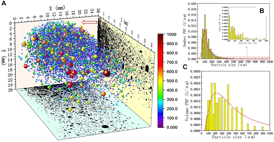
FIGURE 4. (A) Three-dimensional spatial distribution of the plume particle field (B) N-PDF and (C) V-PDF histograms of all the combustion particles.
The N-pdf and V-PDF analyses were performed on all particles (Figure 4B,C). The particle size distribution showed a single peak, and the fraction of particles between the size of 60–150 μm was large (70%). The fraction of particles with a diameter larger than 400 μm was small. Based on the particle diameter, the mean diameters of all the particles in the 3D plume fields were obtained. The D32 = 188.4 μm, and D43 = 280.4 μm (approximately). The mean diameter D50 = 241.1 μm.
Limited by the imaging magnification (×0.1) and pixel size (∼10 um) of Camera 2, the minimum discernible particle size in plume photography results is about 200 um. Based on the X,Y information of each particle their 2D velocity can be obtained. The statistical results show that the particle size distribution for 200–900 um particles with velocity of 200–700 m/s. This also explains why the three-dimensional velocity results of particles cannot be obtained from the hologram in this study under the limited sampling rate.
In the future, this method will be used to obtain the plume characteristic under different pressure in the SRM, and more research on the plume particles near the throat.
Discussion
In this study, a digital holographic measurement system for the identification of condensed-phase particles of an exhaust plume flow in a solid rocket motor (SRM) was developed, which used an aluminized AP/HTPB composite propellant. During the SRM combustion at 10 MPa pressure, the plume particle characteristics in the field of 9–11.5 cm away from the non-expanding 2D nozzle outlet plane was measured and analyzed. In order to improve the efficiency and accuracy of particle identification, a target recognition method suitable for the autonomous recognition of plume particles in a complex background from digital holographic images were established for identification particle size and spatial location of all particles in the plume field. The 3D spatial information (N-PDF, and V-PDF) and mean diameters were obtained and analyzed. The obtained results were as follows.
1 The target recognition method established in this paper can effectively distinguish particles in the plume flow with diameter in the range 50–1,000 μm, with measurement error <5%.
2 About 12,400 individual particles from two thousand holographic images were recognized. Particles size distribution from 65 um to 900 um, 3D spatial information (N-PDF, and V-PDF), and mean diameters were obtained and analyzed.
3 The DIH measurement technology with target recognition method established in this paper can be applied well to real-time online measurement of the 3D dynamic characteristics of the plume particle field anywhere outside of the nozzle outlet of an SRM with highly aluminized propellants.
Data Availability Statement
The original contributions presented in the study are included in the article/Supplementary Material, further inquiries can be directed to the corresponding authors.
Author Contributions
Conceptualization, BJ; methodology, BJ; software, BJ, HX, and SY; validation, SY, YD, and XL; analysis, BJ and PL; data curation, BJ; writing—BJ; All authors have read and agreed to the published version of the manuscript.
Funding
This work was supported by the National Natural Science Foundation of China (Grant number 51706186).
Conflict of Interest
The authors declare that the research was conducted in the absence of any commercial or financial relationships that could be construed as a potential conflict of interest.
Publisher’s Note
All claims expressed in this article are solely those of the authors and do not necessarily represent those of their affiliated organizations, or those of the publisher, the editors and the reviewers. Any product that may be evaluated in this article, or claim that may be made by its manufacturer, is not guaranteed or endorsed by the publisher.
References
1. Blomshield FS. Lessons Learned in Solid Rocket Combustion Instability. AIAA Paper 2007-5803. In: 43rd AIAA/ASME/SAE/ASEE Joint Propulsion Conference & Exhibit; 8-11 July 2007; Cincinnati,OH (2007).
2. Ji S, Wang B, Zhao D. Numerical Analysis on Combustion Instabilities in End-Burning-Grain Solid Rocket Motors Utilizing Pressure-Coupled Response Functions. Aerospace Sci Tech (2020) 98:105701. doi:10.1016/j.ast.2020.105701
3. Ebrahimi HB, Levine J, Kawasaki A. Numerical Investigation of Twin-Nozzle Rocket Plume Phenomenology. J Propulsion Power (2000) 16(2):178–186. doi:10.2514/2.5572
4. Delong YAO, Song C. Study on TDLAS Measurement Method for Plume Velocity of Solid Rocket Motor. J Appl Opt (2020) 41(2):342–347. doi:10.5768/jao202041.0203001
5. Laredo D, McCrorie JI, Vaughn JK, Netzer DW. Motor and Plume Particle Size Measurements in Solid Propellant Micromotors. J Propulsion Power (1994) 10(3):410–418. doi:10.2514/3.23750
6. Liu H, Ao W, Liu P, Hu S, Lv X, Gou D, et al. Experimental Investigation on the Condensed Combustion Products of Aluminized GAP-based Propellants. Aerospace Sci Tech (2020) 97:105595. doi:10.1016/j.ast.2019.105595
7. Liu X, Wen A, Liu H, Liu P. Aluminum Agglomeration on Burning Surface of NEPE Propellants at 3–5 MPa. Propellants, Explosives, Pyrotechnics (2017) 42(3):260–268. doi:10.1002/prep.201600131
8. Glotov OG, Yagodnikov DA, Vorob’ev VS, Zarko VE, Simonenko VN. Ignition, Combustion, and Agglomeration of Encapsulated Aluminum Particles in a Composite Solid Propellant. II. Experimental Studies of Agglomeration. Combust Explos Shock Waves (2007) 43(3):320–333. doi:10.1007/s10573-007-0045-y
9. Glotov OG. Condensed Combustion Products of Aluminized Propellants. II. Evolution of Particles with Distance from the Burning Surface. Combust Explos Shock Waves (2000) 36(4):476–487. doi:10.1007/bf02699478
10. Cauty F, Erades C, Desse JM. Light Deviation Based Optical Techniques Applied to Solid Propellant Combustion. Prog Propulsion Phys (2011) 2:121–134. doi:10.1051/eucass/201102121
11. Devillers R, Nugue M, Tong ACH, Le Besnerais G, Pichillou J. Experimental Analysis of Aluminum-Droplet Combustion in Solid-Propellant Conditions Using Deep Learning. Madrid, Spain: EUCASS 2019 (2019).
12. Jin B-n., Wang Z-x., Xu G, Ao W, Liu P-j. Three-dimensional Spatial Distributions of Agglomerated Particles on and Near the Burning Surface of Aluminized Solid Propellant Using Morphological Digital In-Line Holography. Aerospace Sci Tech (2020) 106:106066. doi:10.1016/j.ast.2020.106066
13. Guildenbecher DR, Cooper MA, Sojka PE. High-Speed (20 kHz) Digital In-Line Holography for Transient Particle Tracking and Sizing in Multiphase Flows. Appl Opt (2016) 55(11):2892–903. doi:10.1364/AO.55.002892
14. Wu YC, Wu XC, Yang J, Zhihua W, Xiang G, Binwu Z, et al. Wavelet-based Depth-Of-Field Extension, Accurate Autofocusing, and Particle Pairing for Digital Inline Particle Holography. Appl Opt (2014) 53(4):556–564. doi:10.1364/ao.53.000556
15. Wu Y, Wu X, Saengkaew S, Meunier-Guttin-Cluzel S, Chen L, Qiu K, et al. Digital Gabor and off-axis Particle Holography by Shaped Beams: A Numerical Investigation with GLMT. Opt Commun (2013) 305:247–254. doi:10.1016/j.optcom.2013.05.009
16. Huang R, Pedoeem J, Chen C. YOLO-LITE: a Real-Time Object Detection Algorithm Optimized for Non-GPU Computers. In: 2018 IEEE International Conference on Big Data (Big Data); Dec 10-13, 2018; Seattle, WA, USA. Piscataway, New Jersey, United States: IEEE (2018). p. 2503–2510.
17. Chen Y, Guildenbecher DR, Hoffmeister KNG, Cooper MA, Stauffacher HL, Oliver MS, et al. Study of Aluminum Particle Combustion in Solid Propellant Plumes Using Digital In-Line Holography and Imaging Pyrometry. Combustion and Flame (2017) 182:225–237. doi:10.1016/j.combustflame.2017.04.016
Keywords: digital in-line holography, solid rocket motor, plume, condensed phase particles, deep learning
Citation: Jin B, Xu H, Yang S, Lei X, Ding Y and Liu P (2022) Digital In-Line Holography of Condensed-Phase Particles in Solid Rocket Motor Plume. Front. Phys. 9:819000. doi: 10.3389/fphy.2021.819000
Received: 20 November 2021; Accepted: 21 December 2021;
Published: 03 February 2022.
Edited by:
Jianglei Di, Guangdong University of Technology, ChinaReviewed by:
Zhixin Wang, Shanghai Space Propulsion Technology Research institute, ChinaYingchun Wu, Zhejiang University, China
Copyright © 2022 Jin, Xu, Yang, Lei, Ding and Liu. This is an open-access article distributed under the terms of the Creative Commons Attribution License (CC BY). The use, distribution or reproduction in other forums is permitted, provided the original author(s) and the copyright owner(s) are credited and that the original publication in this journal is cited, in accordance with accepted academic practice. No use, distribution or reproduction is permitted which does not comply with these terms.
*Correspondence: Bingning Jin, amluYmluZ25pbmdAbndwdS5lZHUuY24=; Peijin Liu, TGl1cGpAbndwdS5lZHUuY24=