- 1Department of Information Communication, Army Academy of Armored Forces, Beijing, China
- 2Center of Vocational Education, Army Academy of Armored Forces, Beijing, China
- 3R and D Center for Intelligent Control and Advanced Manufacturing, Research Institute of Tsinghua University in Shen Zhen, Shen Zhen, China
- 4Troops of PLA, Beijing, China
Holographic stereogram comprises a hotspot in the field of three-dimensional (3D) display. It can reconstruct the light field information of real and virtual scenes at the same time, further improving the comprehensibility of the scene and achieving the “augmentation” of the scene. In this paper, an augmented reality-holographic stereogram based on 3D reconstruction is proposed. First, the point cloud data is generated by VisualSFM software, and then the 3D mesh model is reconstructed by MeshLab software. The obtained scene model and virtual scene are rendered simultaneously to obtain the real and virtual fusion scene. Analysis of experimental results shows that the proposed method can effectively realize augmented reality-holographic stereogram.
Introduction
Holographic stereogram (HS) [1–3] comprises a research hotspot in the field of three-dimensional (3D) display, providing a flexible and efficient means of 3D display. HS is widely used in the military, publicity, commerce, and other fields [4, 5]. Using discrete 2D images with parallax information as the input, the 3D reconstruction of a scene can be obtained after image processing, stereoscopic exposure, and development and fixing. An HS cannot show all the information of the scene but is limited to a certain angle (less than 180°). Moreover, HS does not have the depth information in the scene space, but people can still perceive 3D clues, which depends on the binocular parallax effect [6]. HS discretizes and approximates the continuous 3D light field, which greatly reduces the amount of data. In addition, the scene is not limited to real-world objects, but can also be a 3D model rendered by computer. The diversified scene selection of HS not only enriches its expression ability, but also makes the realization of augmented reality-holographic stereogram (ARHS) possible.
ARHS reconstructs the light field information of real and virtual scenes at the same time [7]. The real-scene data are sampled by the camera, and the virtual scene is rendered by computer software or a program. The organic combination of both can further improve the comprehensibility of the scene and achieve the “augmentation” of the scene. The key to realizing ARHS is the effective fusion of real and virtual scenes. There are three methods in AR to prove the realizability of scene fusion. One is the model-based method, which reconstructs the 3D model of a real scene through a computer, exports the model data to the virtual scene rendering software, and renders the virtual scene at the same time to achieve the fusion effect. This method was first proposed by Breen in 1996 [8], but it was difficult to realize due to technical limitations at that time. The second method of proving the realizability of scene fusion is the depth-based method, which determines the occlusion relationship according to the depth value of the target point, and usually only displays the information near the target point. Wloka et al. proposed a video transparent AR system that can solve the problem of occlusion between a real scene and computer-generated objects [9]. The system calculates the pixel depth value through the stereo matching algorithm and compares the depth value to determine the position relationship between real and virtual scenes. The third method used to prove the realizability of scene fusion is the image-analysis-based method. First, the edge of the real scene-image is detected, the accurate contour is drawn, and then the occlusion relationship between the real and virtual scenes are manually marked and completed. This method makes use of the advantages of an edge detection algorithm to mark each image manually. After the continuous development of algorithms, especially the rise of neural networks, contour extraction has gradually acquired intelligence, and manual marking has been automated, which greatly im-proves the practicability of this third method. Roxas et al. used a semantic segmentation algorithm based on a convolutional neural network (CNN) to obtain more accurate fore-ground segmentation results. In addition, according to the complexity of object boundaries and textures, labels are assigned to real scenes to improve the automation performance [10].
In other fields, research on the display of real- and virtual-scene fusion is also underway. Deng et al. used a reflective polarizer (RP) to realize AR 3D display, which has potential applications in stomatology and vehicle AR display [11]. Shi et al. demonstrated a CNN–based computer-generated holographic (CGH) pipeline capable of synthesizing a photorealistic color 3D hologram from a single RGBD image in real time [12]. Yang et al. proposed a fast CGH method with multiple projection images for a near-eye virtual-reality (VR) and AR 3D display by convoluting the projection images with the corresponding point spread function (PSF) [13].
Recently, using depth-based and image-analysis-based method, we proposed a scene fusion coding method based on instance segmentation and pseudo depth to realize ARHS [14]. However, the scope of application of this method is limited, and the display of a few examples is required; otherwise, a large amount of calculation is required.
In the present work, referring to the model-based method in the AR field, we used VisualSFM and MeshLab software to realize the 3D reconstruction of the scene, import the model into 3D Studio Max software, render the virtual scene at the same time, and then realize the scene fusion. Holographic printing is carried out using our proposed effective perspective image segmentation and mosaicking (EPISM) method [15], and the reconstructed light field is analyzed and discussed, which verifies the effectiveness of the proposed method.
Basic Principles
In our work, the basic steps of ARHS based on 3D reconstruction are as follows. First, the 3D model of a real scene was established by 3D reconstruction. Then, the model was imported into the computer, the virtual scene information was rendered and added, and the effective fusion between the virtual and real scenes was completed according to the preset perspective and occlusion relationship. Finally, it is processed according to the steps of sampling, coding, printing, and display of HS, to realize ARHS.
The core of our method is 3D reconstruction. To verify the effectiveness of the method, we used the 3D reconstruction technology based on multi-view map, which mainly depends on two software packages, i.e., VisualSFM and MeshLab. The fusion of real and virtual scenes depends on 3D Studio Max.
VisualSFM uses a stereo-matching algorithm to detect and match the image feature points, then uses a structure-from-motion (SFM) algorithm to calculate the pose of the camera in space according to the matching data and reconstructs the 3D point-cloud model of the 3D scene. However, the point-cloud model is sparse and in-sufficient for 3D reconstruction. VisualSFM provides the function of calculating dense point clouds, which can store dense point clouds in the computer in the form of data. MeshLab is based on the Poisson surface reconstruction (PSR) algorithm, which can convert dense point-cloud data into a mesh model of a scene. 3D Studio Max can import the previous scene model and render the virtual information at the same time.
Stereo Matching and SFM
Stereo matching refers to the matching of pixel pairs with identical points on multiple perspectives of the same scene, estimating parallax and calculating object-depth information, and preparing for SFM. Before matching, it is necessary to detect the feature points of the image. The Scale invariant feature transform (SIFT) operator is used as a feature point detection tool in VisualSFM.
SIFT has scale and rotation invariance. When the image is rotated and scaled, it still has good detection effect [16, 17]. In addition, it has strong robustness, is suitable for extracting feature point information of scale transformation and various images with angular rotation and has strong accuracy.
SFM determines the spatial and geometric relationship of object points by estimating the changes of the camera’s spatial pose. When the spatial positions of more object points are determined, a sparse 3D point cloud can be obtained. To better represent the mapping relationship between pixels and object points in the SFM process, several coordinate systems must be considered.
• World coordinate system. A 3D coordinate system, which represents the actual coordinates of any object point in space.
• Camera coordinate system. A 3D coordinate system, which represents the spatial pose transformation of the camera to facilitate the expression of its motion process.
• Image-plane coordinate system. A 2D coordinate system with its origin located at the intersection of the camera optical axis and the image, which can represent the coordinates of any pixel point.
• Pixel-plane coordinate system. A 2D coordinate system with its origin in the upper left-hand corner of the image, which can represent the coordinates of any pixel point.
SFM process is the process of projecting the pixels in the pixel plane coordinate system to the world coordinate system. The projection relation is given directly here. For details, please refer to Refs. [18, 19].
where (u, v) represents the coordinates of the image pixel in the pixel-plane coordinate system, (Xw, Yw, Zw) the coordinates of the object point in the world coordinate system, and K the camera internal parameter matrix, which is determined by the structural properties of the camera itself. fx and fy are the normalized focal lengths, s is the tilt factor, and cx and cy are the coordinates of the main point in the image plane coordinate system, both in pixels and known parameters. T is the external parameter matrix, which is determined by the position relationship between the camera and the world coordinate system. R and t represent rotation and translation, respectively, which are unknown parameters. Therefore, the solution of R and t becomes the key to SFM.
The calculation of relative pose R and t between adjacent cameras can be given by singular value decomposition of eigenmatrix E. Eq. 2 gives the calculation method of E
where x' is the 3D point coordinate in the right-hand camera coordinate system and x the 3D point coordinate in the left-hand camera coordinate system. However, the values of their coordinates are unknown. The second calculation method of E is given as follows:
where KrT is the transpose of the internal parameter matrix of the right-hand camera, Kl the internal parameter matrix of the left-hand camera, and F the basic matrix. Here, K is known, and the solution method of the basic matrix is
where qrT is the transpose of the image-plane coordinates of the right-hand camera and ql those of the left-hand camera. They can be calculated directly from the pixel-plane coordinates (u, v).
Thus, the transformation relationship of camera spatial pose can be calculated, and the spatial position of pixels reconstructed.
Computing Dense Point Cloud—Multi-View Stereo
The 3D point cloud obtained by SFM is composed of feature points, so it is sparse. To better reconstruct the 3D scene, it is necessary to densify the sparse point cloud. VisualSFM software can additionally configure the PMVS/CMVS resource package to realize the generation of a dense point cloud. The photos are clustered by CMVS to reduce the amount of dense reconstruction data, and then PMVS is used to generate dense point clouds with real colors through matching, diffusion, and filtering under the constraints of local photometric consistency and global visibility. The basic principle is multi-view stereo (MVS).
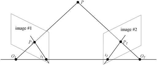
The main difference between MVS and SFM in obtaining a sparse point cloud is that MVS matches all pixels in the image and reconstructs the corresponding spatial position of each pixel to achieve the effect of high-definition reconstruction. To simplify the process of finding homonymous points in two images, epipolar constraints must be introduced. The epipolar constraint describes the constraint formed by the image point and camera optical center under the projection model when the same point is projected on two images from different perspectives, which can reduce the search range when feature point matching.
Referring to Figure 1, the line O1O2 connecting the optical centers of the two cameras is called the baseline, and the intersection of the baseline and the plane of images #1 and #2 is called the base point i1 and i2. The plane O1O2P is called the polar plane, and the intersections i1P1 and i2P2 of the polar and image planes are called the polar lines. If the image point of an object points in space on image #1 is P1, then the image point on image #2 must be P2. The epipolar constraint simplifies the detection and matching of all pixels of the image to the matching of a certain line, which can narrow the search range of feature-point matching and has a more accurate matching effect.
The consistency judgment function cij(p) is used to judge the similarity of the points on the epipolar constraint to complete the feature matching of all pixels, and then the dense point cloud data are generated according to these registered feature points.
where π(p) is a function that makes object point p project to a point on the photograph, Ω(x) defines the area around a point x, and I(x) represent the intensity characteristics of the photo area; ρ (f, g) is used to compare the similarity between two vectors. VisualSFM does not display the dense point cloud on the operation interface but records it in the computer in the form of a data list.
Poisson Surface Reconstruction
Poisson Surface Reconstruction (PSR) is a mesh reconstruction method proposed by Kazhdan et al. in 2006 [20]. It uses the input point-cloud data to build a triangular mesh model and represents the surface reconstruction problem as finding the solution of a Poisson equation. Its core is that the point cloud represents the position of the object surface, and its normal vector represents the internal and external directions. PSR considers all data at the same time without heuristic segmentation and merging. It is a global algorithm, which is conducive to generating smooth surfaces.
By implicitly fitting an indicator function derived from an object, an estimate of a smooth object surface can be given. Letting M represent an area and
where x represents the sampling point. The indicator function can be approximated to

FIGURE 2. Intuitive illustration of Poisson reconstruction in 2D (A) vector field
First, the smoothing filter function
where ⊗ is the convolution symbol for smoothing,
where x. p and x
Using the divergence operator, Eq. 9 can be transformed into a Poisson equation,
The indicator function can be calculated by solving the Poisson equation. The solution of Eq. 10 is obtained by Laplace matrix iteration, which will not be repeated here.
Experiment and Analysis
3D Reconstruction and Data Processing
The dataset “old school gate of Tsinghua University” was used in our experiment [21]. The data were from the State Key Laboratory of pattern recognition, Institute of Automation, Chinese Academy of Sciences, who used a Riegl-LMS-Z420i laser scanner to obtain the data of buildings and take image data at the same time. The accuracy of the laser scanner within 50 m is 10 mm and the scanning-angle interval 0.0057°. The experiment only used 68 images in the dataset, with dimensions of 4,368 × 2,912 pixel. Three images are shown in Figure 3.
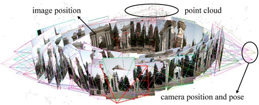
The images were batch-imported into VisualSFM. Stereo matching took 143 s, and 2,278 matches were completed. Matching uses a SIFT operator to form a new intermediate file, which records the matching information in the form of a data list. The file is read, and the sparse 3D point cloud calculated. The point-cloud model and camera spatial pose appear on the software display interface, which takes 196 s, and is shown in Figure 4. The dense point-cloud data are calculated and stored in the computer in the form of a model file and a list file, which takes 10.367 min.
The dense point cloud data were imported into MeshLab for operations such as removing miscellaneous points, meshing, repairing manifold edges, parameterization, and texturing, to obtain the model of the real scene, export the model file and store it in the computer. The model generation process is shown in Figure 5.

FIGURE 5. Model generation process (A) Point cloud with miscellaneous points (B) meshing, and (C) reconstruction result.
The model file was imported into 3D Studio Max software (texture is usually lost in this process) and the spatial pose of the model adjusted. The tree model (virtual scene) was merged and imported to obtain the fusion scene. The scene position relationship was adjusted, and the geometric center of the school gate placed at the origin, with the left- and right-hand trees in front of the gate approximately 1.5 and 3 cm away from the gate, respectively. The camera was located 13.8 cm from the origin for shooting and sampling, and the sampling images are shown in Figure 6. The EPISM method proposed in this paper was used for sampling and coding. In this experiment, the hogel size is 4 mm × 4 mm and the printing area is 8 cm × 8 cm. (For specific details and methods, please refer to Ref. [15].)
Holographic Printing and Reconstruction
The optical experimental scheme was set up as shown in Figure 7. A 400-MW/639-nm single longitudinal mode linearly polarized solid-state laser (CNI MSL-FN-639) was used as the light source, and an electronic shutter (Sigma Koki SSH-C2B) was used to control the exposure time. After passing through a λ/2-wave plate and a polarizing beam splitter (PBS), the laser beam was divided into two beams, namely the object beam and the reference beam. The polarization state of the object beam was adjusted by a λ/2-wave plate to be consistent with the reference beam. The attenuator of the reference beam was adjusted to attain an object reference energy ratio of 1:20. The object beam irradiated the LCD screen after being expanded and reached the holographic plane after being diffused by the scattering film. After filtering and collimating, the uniform plane-wave reference beam was obtained. The object and reference beams interfered with each other after being incident from both sides, and the exposure image information was written. The holographic plate was fixed on a KSA300 X-Y linear displacement platform; the positioning accuracy of the platform in the horizontal and vertical directions was 1 μm. The displacement platform was controlled by an MC600 programmable controller.
Holographic plate is a silver salt dry plate. After holographic printing, it is developed, fixed, and bleached. The holographic plate can reconstruct 3D images in the conjugate of original reference light after developing and bleaching. As shown in Figure 8, the reconstructed image was taken with a Canon camera and a macro lens with a focal length of 100 mm, which was placed approximately 30 cm in front of the holographic plate.
Results and Analysis
In this subsection, we show and analyze the 3D information of the obtained hologram, including horizontal parallax, vertical parallax, and depth information. It should be noted that although our experimental system can display ±19.8° horizontal and vertical field angles, the actual displayed field angle cannot meet this standard to display the main part of the fusion scene.
Figure 9 shows the horizontal parallax information of the reconstructed image at the same vertical position, in which (C) and (D) show some details in the yellow rectangles of (A) and (B), respectively. As can be seen from the information in the white elliptical curves in (C) and (D), the tree in (D) on the left-hand side of the middle door blocks most of the doorway, and the tree on the right-hand side fails to block the doorway, while (D) depicts the opposite. This shows that the perspective of (A) is on the left and that of (B) is on the right. The angle between them is approximately 10°.
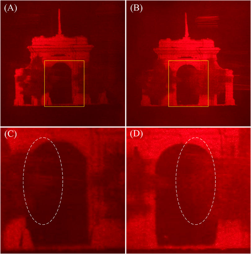
FIGURE 9. Horizontal parallax information of reconstructed image (A) Left-hand perspective (B) right-hand perspective (C) detail of (A), and (D) detail of (B).
Figure 10 shows the vertical parallax information of the reconstructed image in the same horizontal position, where (B) and (D) show some of the details in the yellow rectangles of (A) and (C), respectively. For ease of observation, the edge contour at the logarithmic root is depicted in the figures. From information in the white elliptical curves in (B) and (D), the bottom of the tree root in (B) is nearly parallel to the bottom of the school gate, while the bottom of the tree root in (D) is higher. This shows that (A) is a head’s-up view and (C) is a bottom view. The angle between them is approximately 5°.
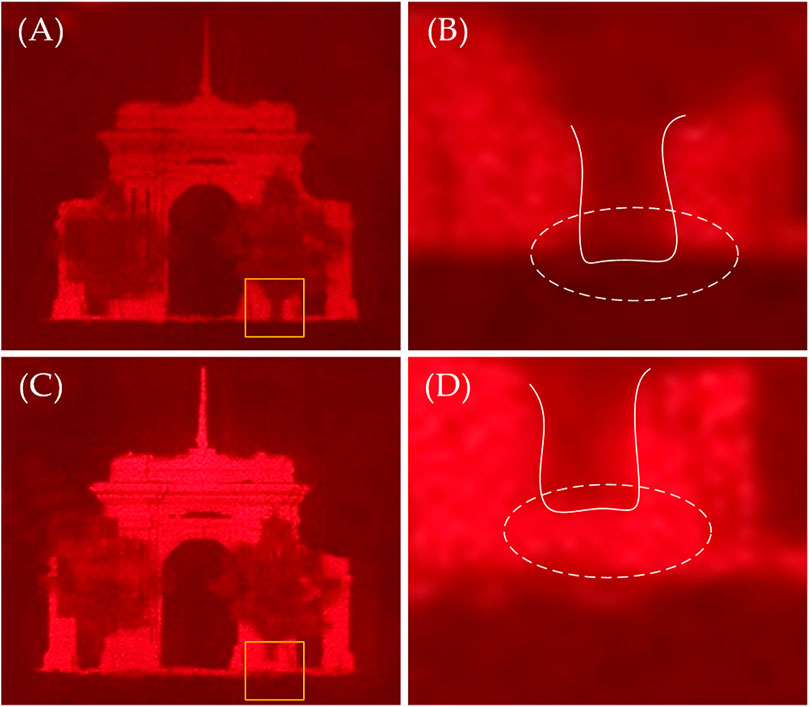
FIGURE 10. Vertical parallax information of the reconstructed image (A) Head up view (B) detail of (A) (C) bottom view, and (D) detail of (C).
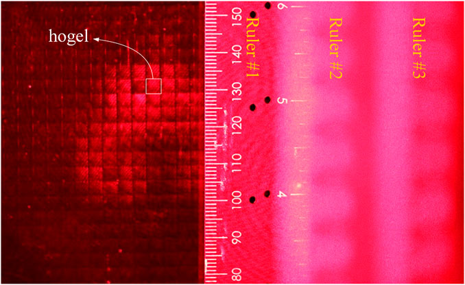
Figures 11,12 show the depth information of the reconstructed image. Here, only the left-hand side of the fusion scene is of importance. To facilitate analysis, three rulers are placed in the reconstructed light field, one is in the hologram plate, one is 13.8 cm away from the hologram, and the other is 15.3 cm away from the hologram. When the camera focuses on Ruler #1, as shown in Figure 11, the grid shape of the hogel is clearly visible, and the reconstructed image cannot be observed.
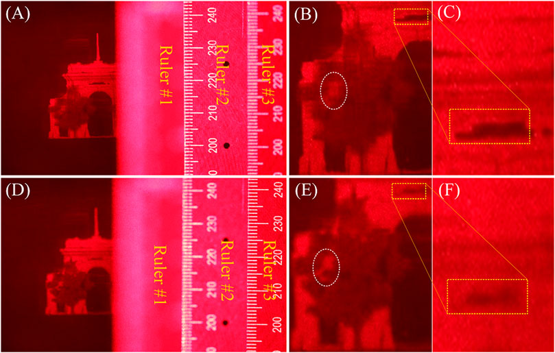
FIGURE 12. Comparation of depth information (A) Camera focused on Ruler #2 (B) detail of (A), and (C) detail of (B) (D) Camera focused on Ruler #3 (E) detail of (D), and (F) detail of (E).
When the camera focuses on Ruler #2, as shown in Figure 12 (A-C), the details of the tree circled by the white elliptical curve are blurred, but an incomplete part of the school gate in the yellow box is clearly displayed. When the camera focuses on Ruler #3, as shown in Figure 12 (D-F), the opposite is true. This shows that the scene protrudes from the holographic plate display, and that the distance is equal to the sampling distance; in addition, the depth information between the scenes also conforms to the preset relationship during sampling. The depth information of the scene can be expressed effectively.
Conclusion
In this paper, an augmented reality–holographic stereogram based on 3D reconstruction is proposed that provides an effective means for augmented holographic 3D display of a scene. The relevant research results can be applied to medical, military, and other fields. In the 3D reconstruction, two software programs were used—VisualSFM and MeshLab. The basic principle of the 3D reconstruction algorithm employed in the software is introduced, and the 3D reconstruction completed by using an image dataset depicting the “old school gate of Tsinghua University.” We rendered, sampled, and encoded the 3D model and the virtual scene at the same time, and then holographic printing was carried out to obtain the holographic stereogram with full parallax. Results and analysis verified the effectiveness of the proposed method. Since we were concerned about the effectiveness of the method, we selectively ignored the poor effect of the 3D reconstruction approach used, especially the loss of texture information when the model was imported into the 3D modeling software. The 3D model obtained from 68 images has obvious holes. To obtain better results, we must increase the number of images or use other methods to complete 3D reconstruction, which is also our next planned research direction.
Data Availability Statement
The original contributions presented in the study are included in the article/supplementary material further inquiries can be directed to the corresponding authors.
Author Contributions
Conceptualization, YL and XY; methodology, YL, TJ, and XY; software, QQ, PZ, and TJ; validation, PL, X.J, and QY; formal analysis, YL and TJ; resources, XY and PZ; data curation, PZ and XJ; writing—original draft preparation, YL, QQ, and QY; writing—review and editing, YL and QZ; visualization, PZ and QQ; supervision, XJ and XY; project administration, XY; funding acquisition, XY All authors have read and agreed to the published version of the manuscript.
Funding
This research was funded by the National Key Research and Development Program of China (Grant No. 2017YFB1104500), National Natural Science Foundation of China (Grant No. 61775240), and Foundation for the Author of National Excellent Doctoral Dissertation of the People’s Republic of China (Grant No. 201432).
Conflict of Interest
The authors declare that the research was conducted in the absence of any commercial or financial relationships that could be construed as a potential conflict of interest.
Publisher’s Note
All claims expressed in this article are solely those of the authors and do not necessarily represent those of their affiliated organizations, or those of the publisher, the editors and the reviewers. Any product that may be evaluated in this article, or claim that may be made by its manufacturer, is not guaranteed or endorsed by the publisher.
References
1. Su J, Yan X, Huang Y, Jiang X, Chen Y, Zhang T. Progress in the Synthetic Holographic Stereogram Printing Technique. Appl Sci (2018) 8(6):851. doi:10.3390/app8060851
2. Yamaguchi M. Light-field and Holographic Three-Dimensional Displays [Invited]. J Opt Soc Am A (2016) 33(12):2348–64. doi:10.1364/JOSAA.33.002348
3. Choi YS, Lee S, Jung JY, Jeong KY, Park HG, Seo MK. Optical Metasurface‐Based Holographic Stereogram. Adv Opt Mater. (2020) 8(8):1901970. doi:10.1002/adom.201901970
4. Liu P, Sun X, Zhao Y, Li Z. Ultrafast Volume Holographic Recording with Exposure Reciprocity Matching for TI/PMMAs Application. Opt Express (2019) 27(14):19583–95. doi:10.1364/OE.27.019583
5. Jiang Q, Jin G, Cao L. When Metasurface Meets Hologram: Principle and Advances. Adv Opt Photon (2019) 11(3):518–76. doi:10.1364/AOP.11.000518
6. Ning Q. Binocular Disparity and the Perception of Depth. Neuron (1997) 18(3):359–68. doi:10.1016/S0896-6273(00)81238-6
7. He Z, Sui X, Jin G, Cao L. Progress in Virtual Reality and Augmented Reality Based on Holographic Display. Appl Opt (2019) 58(5):A74–A81. doi:10.1364/AO.58.000A74
8. Breen DE, Whitaker RT, Rose E, Tuceryan M. Interactive Occlusion and Automatic Object Placement for Augmented Reality. Computer Graphics Forum (1996) 15(3):11–22. doi:10.1111/1467-8659.1530011
9. Wloka MM, Anderson BG. Resolving Occlusion in Augmented Reality. In: Proceedings of the 1995 symposium on Interactive 3D graphics, April 9–12, 1995, Monterey, CA. New York, NY, USA (1995). p. 5–12. doi:10.1145/199404.199405
10. Roxas M, Hori T, Fukiage T, Okamoto Y, Oishi T. Occlusion Handling Using Semantic Segmentation and Visibility-Based Rendering for Mixed Reality. In: Proceedings of the 24th ACM Symposium on Virtual Reality Software and Technology, November 28, 2018–December 1, 2018, Tokyo, Japan. New York, NY, USA (2018). doi:10.1145/3281505.3281546
11. Li Q, He W, Deng H, Zhong F-Y, Chen Y. High-performance Reflection-type Augmented Reality 3D Display Using a Reflective Polarizer. Opt Express (2021) 29(6):9446–53. doi:10.1364/OE.421879
12. Shi L, Li B, Kim C, Kellnhofer P, Matusik W. Author Correction: Towards Real-Time Photorealistic 3D Holography with Deep Neural Networks. Nature (2021) 593(7849):E13. doi:10.1038/s41586-021-03476-5
13. Yang X, Zhang H, Wang Q-H. A Fast Computer-Generated Holographic Method for VR and AR Near-Eye 3D Display. Appl Sci (2019) 9(19):4164. doi:10.3390/app9194164
14. Liu Y, Yan X, Liu X, Wang X, Jing T, Lin M, et al. Fusion Coding of 3D Real and Virtual Scenes Information for Augmented Reality-Based Holographic Stereogram. Front Phys (2021) 9:736268. doi:10.3389/fphy.2021.736268
15. Su J, Yuan Q, Huang Y, Jiang X, Yan X. Method of Single-step Full Parallax Synthetic Holographic Stereogram Printing Based on Effective Perspective Images' Segmentation and Mosaicking. Opt Express (2017) 25(19):23523–44. doi:10.1364/OE.25.023523
16. Lowe DG. Distinctive Image Features from Scale-Invariant Keypoints. Int J Computer Vis (2004) 60:91–110. doi:10.1023/B:VISI.0000029664.99615.94
17. Lowe DG. Object Recognition from Local Scale-Invariant Features. In: Proceedings of the seventh IEEE international conference on computer vision; 20-27 Sept.1999; Kerkyra, Greece. IEEE (1999). p. 1150–7. doi:10.1109/ICCV.1999.790410
18. Lucieer A, Jong SMd., Turner D. Mapping Landslide Displacements Using Structure from Motion (SfM) and Image Correlation of Multi-Temporal UAV Photography. Prog Phys Geogr Earth Environ (2014) 38(1):97–116. doi:10.1177/0309133313515293
19. Wallace L, Lucieer A, Malenovský Z, Turner D, Vopěnka P. Assessment of forest Structure Using Two UAV Techniques: A Comparison of Airborne Laser Scanning and Structure from Motion (SfM) point Clouds. Forests (2016) 7(3):62. doi:10.3390/f7030062
20. Kazhdan M, Bolitho M, Hoppe H. Poisson Surface Reconstruction. In: Proceedings of the Fourth Eurographics Symposium on Geometry Processing. Sardinia, Italy: Cagliari (2006). June 26-28. doi:10.5555/1281957.1281965
21.Robot Vision Group. 3D Reconstruction Dataset (nd). Available at: http://vision.ia.ac.cn/data.
Keywords: holography, holographic stereogram, optical field information manipulation, augmented reality, 3D display
Citation: Liu Y, Jing T, Qu Q, Zhang P, Li P, Yang Q, Jiang X and Yan X (2022) An Augmented-Reality Holographic Stereogram Based on 3D Optical Field Information Manipulation and Reconstruction. Front. Phys. 9:828825. doi: 10.3389/fphy.2021.828825
Received: 04 December 2021; Accepted: 09 December 2021;
Published: 17 January 2022.
Edited by:
Xing Fu, Tsinghua University, ChinaReviewed by:
Binbin Yan, Beijing University of Posts and Telecommunications (BUPT), ChinaPing Su, Tsinghua University, China
Copyright © 2022 Liu, Jing, Qu, Zhang, Li, Yang, Jiang and Yan. This is an open-access article distributed under the terms of the Creative Commons Attribution License (CC BY). The use, distribution or reproduction in other forums is permitted, provided the original author(s) and the copyright owner(s) are credited and that the original publication in this journal is cited, in accordance with accepted academic practice. No use, distribution or reproduction is permitted which does not comply with these terms.
*Correspondence: Xiaoyu Jiang, amlhbmd4aWFveXUyMDA3QGdtYWlsLmNvbQ==; Xingpeng Yan, eWFueHAwMkBnbWFpbC5jb20=
†These authors have contributed equally to this work
 Yunpeng Liu1†
 Xingpeng Yan