- 1Applied Physics Division, Soreq NRC, Yavne, Israel
- 2Physics Department, Weizmann Institute, Rehovot, Israel
Optical vortex beams are light beams that can carry orbital angular momentum (OAM). Hence, such beams may serve as potential candidates for carriers of information in optical communication and quantum optics applications. This is owing to their spatial orthogonality, as these beams can be combined (multiplex) or separated (demultiplexed). We recently demonstrated a new method to detect OAM states by using a 3D-direct laser printing fabrication process. Measuring the mode-sorter performance was challenging, mainly due to mechanical and optical sensitivities originated from misalignments. In this work, this sensitivity was thoroughly examined. Pure OAM states having lateral and angular misalignments relative to the mode-sorter were introduced, and cross-talk between resolved states was theoretically simulated. The system is relatively vulnerable to small misalignments, which challenge its implementations in free-space communication systems. However, this might be an advantage for counseled communication, in which eavesdropping becomes more challenging, due to the angle-dependent increased modal cross-talk.
Introduction
Optical vortex beams are characterized by a winding azimuthal phase, exp (ilϕ), where l is the topological charge and ϕ the azimuthal angle [2]. These beams can carry orbital angular momentum (OAM). This unique property enables implementations of such beams in various applications, including particle manipulation [3], microfabrication [4], astronomy [5], quantum optics [6], high-resolution microscopy [7], and space-division multiplexed communication systems [8]. There are several types of beams that can carry OAM. A commonly used type is the Laguerre-Gaussian (LG) family of beams which is an example of a set of vortex beams that are also solutions of the paraxial Helmholtz equation. In this case, beams with different OAM values are orthogonal; hence, they can be spatially multiplexed and demultiplexed on the same physical channel. These beams can then be used as carriers of information, thereby increasing the information capacity of an optical communication channel [9]. An efficient way to separate OAM states is by applying a Cartesian to log-polar transformation, based on two refractive optical elements [10]. This transformation maps the azimuthal phase profile of an OAM mode into a tilted planar wavefront. As a result, linear combination of OAM states can be simultaneously transformed into a set of planar waves with tilted wavefronts, where the tilt angle depends on the topological charge. These tilted waves can therefore be easily separated in the far field by a lens, enabling OAM analysis, as each mode is located at a different location on a detector. The desired two refractive optical elements are characterized by a non-trivial 3D shapes. Hence, reaching small scale, 3D, and high optical quality is a challenging task. Conventional implementations of such transformation are based on spatial light modulators (SLMs) [11], or large-scale (cm) diamond-turned surfaces [10]. In general, fabrication or manufacturing of small-scale (below hundreds of micrometers) high-quality optical surfaces, characterized by tens of nanometer surface roughness (RMS) is a challenging task. An innovative new approach was able to minimize the two elements into only one, along with 2D high-resolution diffractive surfaces using electron beam lithography [12, 13]. Furthermore, the generation of vortex beams (l ≤ 1) and mode analysis was demonstrated in an all-fiber device [14]. However, all mentioned approaches do not provide direct integration to other optical elements (such as optical fiber), enable cost-effective processes, or provide simple and straightforward lithography procedures for various states. Our recent work showed a new fabrication method that provides high-quality and integrated mode-sorter, based on the two optical elements [1]. This method used a 3D-Direct laser writing (3D-DLW) [15] system, which is based on a nonlinear two-photon absorption process [16]. This concept allows reaching accurate 3D elements of complicated surfaces using the polymerization of a light-sensitive material volume (Voxel). Although implementations of 3D-DLW technology for micro-optics devices are widely reported [15–20], we were able to harness, for the first time, this platform for analyzing OAM modes using the transformation optics theory [21, 22]. This approach may induce new and exciting opportunities for vortex beam detection and analysis in integrated devices, in communication systems, or for quantum optical applications. In our previous work [1], we demonstrated that the two-element 3D-printed free-space mode sorter is capable of handling both pure and mixed vortex beams with topological charges
Principle of the OAM mode-sorter
The Cartesian to log-polar transformation is constructed by two refractive optical elements [11]. These two elements map the coordinates of the incoming beam (in the x-y plane) to an output plane (u-v) using the following relations:
The coordinates u and v describe the Cartesian coordinates at the first element’s Fourier plane. The parameter a is a scaling factor, equals to d/2π, as d is the width of the second element, and b determines the beam location along the v axis. The elements’ surfaces are hereby described:
Z1 and Z2 describe the height profiles of the first and second element, accordingly. The distance between the elements is determined by f, and the material and air refractive indices are denoted as nm and nair accordingly. Modes carrying OAM values that pass through the second element are characterized by rectangular shapes and tilted wave-fronts, dictated by 2πl. Introducing a lens to the tilted waves will result in a focus movement perpendicular to the elongated diffraction limited spot size, by the following connection:
Theoretical design and calculations
In order to reach optimal phase elements, based on the two surfaces provided in Eqs 3, 4, a simulation code based on a split-step Fourier method [23] was used to study the OAM beam propagation through those surfaces. In this way, the elements’ functionality was explored and tailored to the experimental system, as the free parameters were determined. The parameters a, b, and f were chosen to be 19, 25, and 800 μm, accordingly. The final obtained elements are brought in Figure 1, as 3D structural representation (top) and 2D surfaces and phase modulations (bottom) can be seen. The lateral dimensions of the first element were chosen to be 100 × 100 μm2 reaching 12.5 μm at maximum height. The second element lateral size was 160 × 100 μm2 with maximal height of 30 μm. Figure 2 provides a schematic illustration of the operating principle. Here, an OAM mode of l = 1, characterized by a ring-shaped intensity profile passes through the first element, as the ring gradually becomes open until reaching a rectangular shape at the second element plane. The second element return the mode’s initial phase. Then, a lens focuses the mode into an elongated shape at the detector. Combined representations of the mode’s intensity and phase are also provided before and after the elements, as brightness and colors refer, respectively, to intensity and phase of each beam. Figure 3 provides further understanding of the OAM mode sorter operation, as front view intensity and phase calculations of l = 0 and l = 1 modes can be seen in the vicinity of Element 2 (surface Z2). Here, the two modes possess unresolved phase distribution prior entering the element. However, passing through the second element reorganizes the phases according to the OAM values. It is worth emphasizing that the intensity profile of all modes remains the same before and after each element, as only the phase is transformed, which enables a gradient phase change that is manifested in the focused spot position variations on the detector.
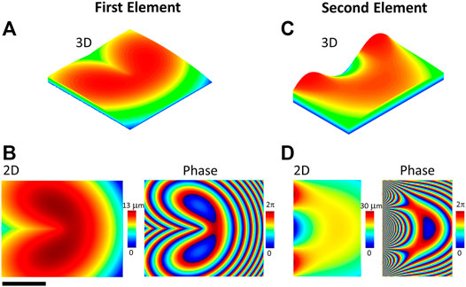
FIGURE 1. The mode-sorter comprising two elements. 3D (A,C) and 2D (B,D) representations of the first (A,B) and second (C,D) elements are presented. In 2D, both height and phase accumulation are described. Scale bar, 50 μm.
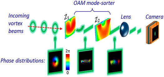
FIGURE 2. Schematic illustration of the mode-sorter as incoming l = 1 OAM mode propagates through the elements. Additional phase and intensity profiles are presented at certain locations with respect to the two elements.
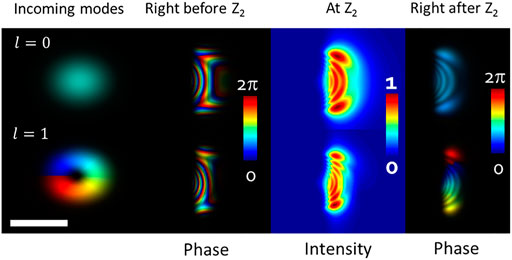
FIGURE 3. Combined representations of the intensities and phases of modes l = 0, 1 are provided before and as after the elements, as brightness and colors refer, respectively, to intensity and phase of each beam. Scale bar, 50 μm.
Nominal performance of the mode-sorter
The nominal performance of the OAM mode-sorter is hereby described. This means that OAM states were injected to the mode-sorter perpendicular to the elements, with no tilt or spherical aberration. The detector that registered the incoming mode-dependent spots was also located at the center of the beam’s axis (for l = 0). This provides a reference point for further understanding the sensitivity and misalignment issues. By using a measurement system, consisting of a CW laser source (690 nm), phase-only spatial light modulator (SLM), and additional optics, the mode-sorter performance was examined, according to a previous work [1]. The SLM provided various OAM modes, −3 ≤l ≤ 3, that propagated toward the mode sorter two-element system, which were than detected using a CCD. The element fabrication process, detailed measurement system, and additional results and information are further elaborated in a previous work [1]. Figure 4 provides the experimental results along with predicted simulations of the mode-sorter functionality for the mentioned OAM values at the detector plane. The incoming modes are also provided for convenience. It can be seen that the modes are clearly resolved, as various states are introduced to the system. High l values may cause fringes that lower the ability to determine the OAM state. In general, small beams have short Reighley length. When working with longer distances, the beam carries a spherical phase front rather a plane one. This induces fringes and reduces the device performance to detect accurately OAM states. Furthermore, the influence of production inaccuracies tends to minimize as dimensions increase. The mode sorter consists of two refractive phase elements. The coupling loss for an incoming LG10 mode in this system is 30%. The main cause for such losses is due to Fresnel reflections. Additional losses such as absorption and diffraction caused by the device itself are negligible. This is because it is a phase-only device that is made of a transparent polymer.
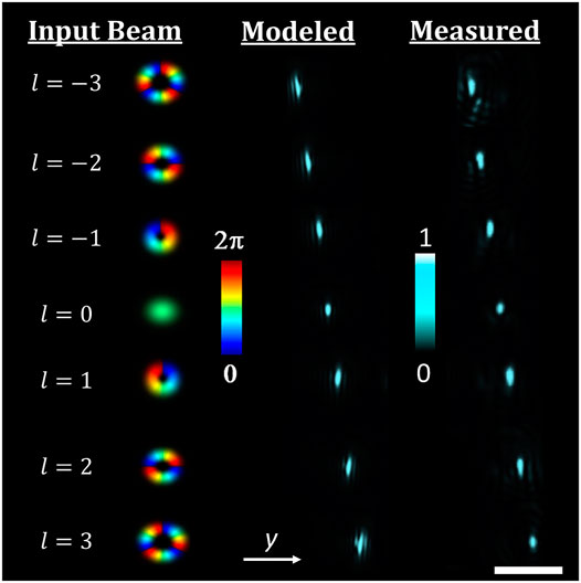
FIGURE 4. Simulation results of a free-space OAM mode-sorter followed by experimental results. Each OAM state propagates onto a different location on the detector, with correlation to the state’s topological charge. Scale bar, 100 μm.
Sorting sensitivity
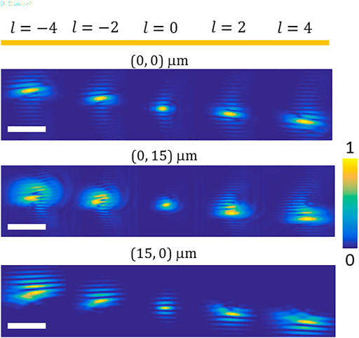
In this chapter, the system performance is investigated under lateral misalignment of the incoming beam. Such misalignment often happens in free optic applications. This was carried out by moving the mode-sorter laterally to the beam propagation axis. Since the two-phase structures consisting the mode-sorter device have a complex 3D surface, the performance and OAM spectral purity are expected to be affected. It is convenient to describe the OAM of an LG light beam by its optical axis. Hence, by choosing different axis, these light beams could be represented by a span of various LG modes, which also serve as orthogonal states of the paraxial wave equation, providing discrete OAM spectrum. A lateral displacement of a symmetric beam will not alter its OAM value [24]. However, such a displacement may alter a single photon OAM state, with respect to the reference axis. Meaning, the pure OAM state of an individual photon will be represented by a superposition of many OAM states in the new displaced coordinate system [25]. In other words, by changing the observation axis, the mode purity is disturbed and redistributed as a span of discrete states. Hence, the ability to analyze the OAM state of a certain mode becomes more challenging due to this spectrum broadening. As shown here and in [1], the mode-sorter is capable of detecting various OAM states. However, exploring the system’s performance upon displacements or due to beam wondering effects should be further investigated. In this work, we characterize theoretically the system ability to detect incoming OAM states, when the whole mode-sorter system is displaced from its center
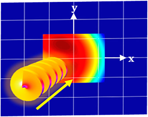
FIGURE 5. Schematic representation of the lateral displacement calculative method. The entire two-element system moves together in each direction (only the first element is shown).
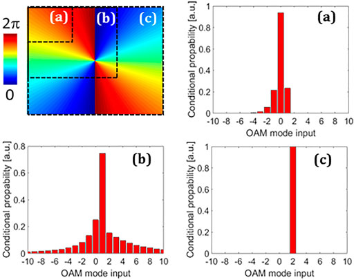
FIGURE 6. OAM attained spectrum, in the case of l = 2, when phase analysis is carried out for different areas and locations in the phase distribution. The pure state is screened, as modal spanning is formed.
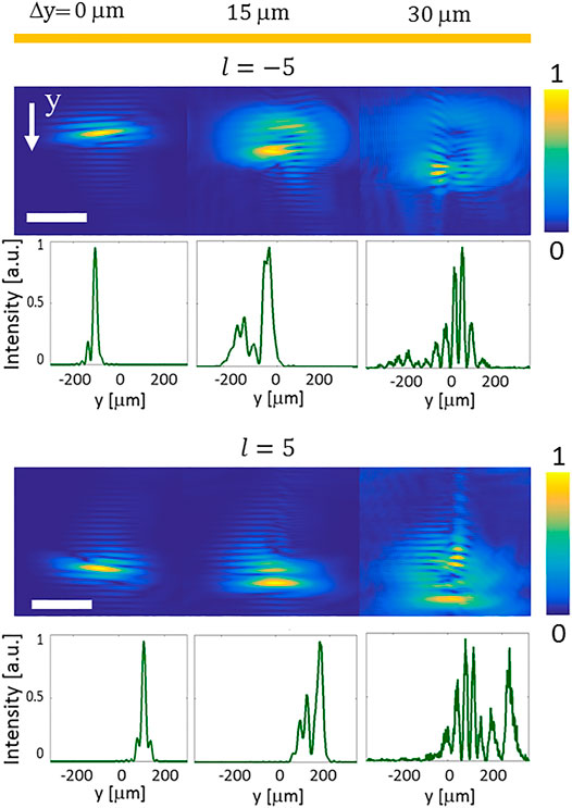
FIGURE 8. Intensity profiles of the
The system’s modal cross-talk
Here, the cross-talk between various OAM states due to lateral and angular misalignment is investigated. This provides a two dimensional map of all modes there were sent and detected.
Another representation of the modal purity could be described as the modal cross-talk. In this approach, the system misalignment
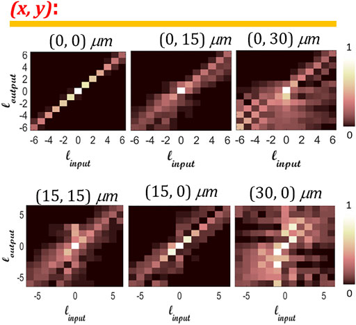
FIGURE 9. Calculated cross-talk matrix for 13 modes, for various cases of system displacements (15, 30 μm).
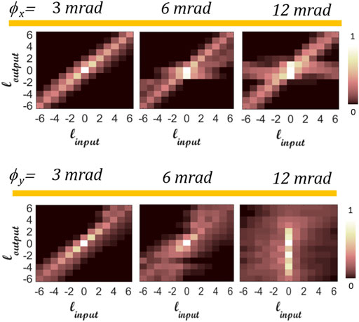
FIGURE 10. Calculated cross-talk matrix for 13 modes, as the incoming modes propagate off-axis to the mode-sorter center. Each case describes modes that propagate with an additional linear phase gradient terms.
Conclusion
The system is highly sensitive to misalignments, which is a disadvantage in most cases. However, this might be an advantage for private/secret communication, in which “listening” is almost impossible. The operation of the 3D-miniature mode-sorter system was examined. Two concerns were theoretically investigated, shedding more light on the system functionality to serve as a key element for future OAM-based communication systems: first, the system performance when misalignments (respect to the optical axis) are introduced; second, the ability of the mode-sorter to distinguish the OAM states as the beams arrive from various directions, as each beam has a different tilt, but still reach the center of the system. All calculations were based on a mode-sorter that was experimentally capable to separate pure and mixed OAM states, up to
The conclusion of the carried out analysis of the mode-sorter exhibits high sensitivity to optical and mechanical misalignments. This is commonly conceived as a disadvantage in most cases. However, this might be an advantage for secure communication, where the eavesdropper encounters signal broadening and impure states. Thus, our future goal is to construct a free-space integrated communication system, based on the reported insights. Furthermore, the mode-sorter could also be integrated on top of a suitable optical vortex fibers [26–28], combined with a collimating lens. This would enable precise alignment between the fiber core and the mode-sorter center, with low-probability for tilted modes, along with fiber-based communication system foothold.
Data Availability Statement
The original contributions presented in the study are included in the article/Supplementary Material, further inquiries can be directed to the corresponding authors.
Author Contributions
All authors listed have made a substantial, direct, and intellectual contribution to the work and approved it for publication.
Funding
This work was supported by the Pazy foundation.
Conflict of Interest
The authors declare that the research was conducted in the absence of any commercial or financial relationships that could be construed as a potential conflict of interest.
Publisher’s Note
All claims expressed in this article are solely those of the authors and do not necessarily represent those of their affiliated organizations, or those of the publisher, the editors, and the reviewers. Any product that may be evaluated in this article, or claim that may be made by its manufacturer, is not guaranteed or endorsed by the publisher.
References
1. Lightman S, Hurvitz G, Gvishi R, Arie A. Miniature Wide-Spectrum Mode Sorter for Vortex Beams Produced by 3D Laser Printing. Optica (2017) 4:605–10. doi:10.1364/optica.4.000605
2. Allen L, Beijersbergen MW, Spreeuw RJC, Woerdman JP. Orbital Angular Momentum of Light and the Transformation of Laguerre-Gaussian Laser Modes. Phys Rev A (1992) 45:8185–9. doi:10.1103/physreva.45.8185
3. Garcés-Chávez V, McGloin D, Padgett MJ, Dultz W, Schmitzer H, Dholakia K. Observation of the Transfer of the Local Angular Momentum Density of a Multiringed Light Beam to an Optically Trapped Particle. Phys Rev Lett (2003) 91:93602. United States.
4. Hamazaki J, Morita R, Chujo K, Kobayashi Y, Tanda S, Omatsu T. Optical-vortex Laser Ablation. Opt Express (2010) 18:2144–51. doi:10.1364/oe.18.002144
5. Swartzlander, Jr. GA, Ford EL, Abdul-Malik RS, Close LM, Peters MA, Palacios DM, et al. Astronomical Demonstration of an Optical Vortex Coronagraph. Opt Express (2008) 16:10200–7. OSA. doi:10.1364/oe.16.010200
6. García-Escartín JC, Chamorro-Posada P. Quantum Multiplexing with the Orbital Angular Momentum of Light. Phys Rev A - Mol Opt Phys (2008) 78:1–10.
7. Hell SW, Wichmann J. Breaking the Diffraction Resolution Limit by Stimulated Emission: Stimulated-Emission-Depletion Fluorescence Microscopy. Opt Lett (1994) 19:780–2. doi:10.1364/ol.19.000780
8. Bozinovic N, Yue Y, Ren Y, Tur M, Kristensen P, Huang H, et al. Terabit-Scale Orbital Angular Momentum Mode Division Multiplexing in Fibers. Science (2013) 340:1545–8.
9. Baghdady J, Miller K, Morgan K, Byrd M, Osler S, Ragusa R, et al. Multi-gigabit/s Underwater Optical Communication Link Using Orbital Angular Momentum Multiplexing. Opt Express (2016) 24:9794. doi:10.1364/oe.24.009794
10. Lavery MPJ, Robertson DJ, Berkhout GCG, Love GD, Padgett MJ, Courtial J. Refractive Elements for the Measurement of the Orbital Angular Momentum of a Single Photon. Opt Express (2012) 20:2110–5. doi:10.1364/oe.20.002110
11. Berkhout GC, Lavery MP, Courtial J, Beijersbergen MW, Padgett MJ. Efficient Sorting of Orbital Angular Momentum States of Light. Phys Rev Lett (2010) 105:153601–11. doi:10.1103/PhysRevLett.105.153601
12. Ruffato G, Massari M, Parisi G, Romanato F. Test of Mode-Division Multiplexing and Demultiplexing in Free-Space with Diffractive Transformation Optics. Opt Express (2017) 25:7859. doi:10.1364/oe.25.007859
13. Ruffato G, Massari M, Romanato F. Compact Sorting of Optical Vortices by Means of Diffractive Transformation Optics. Opt Lett (2017) 42:551. doi:10.1364/ol.42.000551
14. Mao D, Zheng Y, Zeng C, Lu H, Wang C, Zhang H, et al. Generation of Polarization and Phase Singular Beams in Fibers and Fiber Lasers. Adv Photon (2021) 3:1–18. doi:10.1117/1.ap.3.1.014002
15. Zhou X, Hou Y, Lin J. A Review on the Processing Accuracy of Two-Photon Polymerization. AIP Adv (2015) 5. doi:10.1063/1.4916886
16. Chichkov BN, Ostendorf A. Two-Photon Polymerization: A New Approach to Micromachining. Photon Spectra (2006) 40:72–9.
17. Schiappelli F, Kumar R, Prasciolu M, Cojoc D, Cabrini S, De Vittorio M, et al. Efficient Fiber-To-Waveguide Coupling by a Lens on the End of the Optical Fiber Fabricated by Focused Ion Beam Milling. Microelectronic Eng (2004) 73-74:397–404. doi:10.1016/s0167-9317(04)00143-1
18. Kabouraki E, Giakoumaki AN, Danilevicius P, Gray D, Vamvakaki M, Farsari M. Redox Multiphoton Polymerization for 3D Nanofabrication. Nano Lett (2013) 13:3831–5. doi:10.1021/nl401853k
19. Thiel M, Fischer J, Von Freymann G, Wegener M. Direct Laser Writing of Three-Dimensional Submicron Structures Using a Continuous-Wave Laser at 532 Nm. Appl Phys Lett (2010) 97:10–3. doi:10.1063/1.3521464
20. Lightman S, Gvishi R, Hurvitz G, Arie A. Shaping of Light Beams by 3D Direct Laser Writing on Facets of Nonlinear Crystals. Opt Lett (2015) 40:4460. doi:10.1364/ol.40.004460
21. Hossack WJ, Darling AM, Dahdouh A. Coordinate Transformations with Multiple Computer-Generated Optical Elements. J Mod Opt (1987) 34:1235–50. doi:10.1080/09500348714551121
22. Bryngdahl O. Geometrical Transformations in Optics*. J Opt Soc Am (1974) 64:1092. doi:10.1364/josa.64.001092
23. Sinkin OV, Holzlohner R, Zweck J, Menyuk CR. Optimization of the Split-step Fourier Method in Modeling Optical-Fiber Communications Systems. J Lightwave Technol (2003) 21:61–8. OSA. doi:10.1109/jlt.2003.808628
25. Molina-Terriza G, Torres JP, Torner L. Management of the Angular Momentum of Light: Preparation of Photons in Multidimensional Vector States of Angular Momentum. Phys Rev Lett (2002) 88:4.
26. Jiang Y, Ren G, Shen Y, Xu Y, Jin W, Wu Y, et al. Two-dimensional Tunable Orbital Angular Momentum Generation Using a Vortex Fiber. Opt Lett (2017) 42:5014–7. doi:10.1364/ol.42.005014
27. Ramachandran S, Kristensen P. Optical Vortices in Fiber. Nanophotonics (2013) 2:455–74. doi:10.1515/nanoph-2013-0047
Keywords: vortex beam, 3D printing, orbital angular moment, mode sorter, phase modulated
Citation: Lightman S, Wengrowitcz JM, Teitelboim A, Gvishi R and Hurvitz G (2022) Exploring for New Insights in the Performance of a 3D Orbital Angular Momentum Mode-Sorter. Front. Phys. 10:835159. doi: 10.3389/fphy.2022.835159
Received: 14 December 2021; Accepted: 17 January 2022;
Published: 04 March 2022.
Edited by:
Pei Zhang, Xi’an Jiaotong University, ChinaReviewed by:
Dong Mao, Northwestern Polytechnical University, ChinaCuicui Lu, Beijing Institute of Technology, China
Copyright © 2022 Lightman, Wengrowitcz, Teitelboim, Gvishi and Hurvitz. This is an open-access article distributed under the terms of the Creative Commons Attribution License (CC BY). The use, distribution or reproduction in other forums is permitted, provided the original author(s) and the copyright owner(s) are credited and that the original publication in this journal is cited, in accordance with accepted academic practice. No use, distribution or reproduction is permitted which does not comply with these terms.
*Correspondence: Shlomi Lightman, c2hsb21pbGlAc29yZXEuZ292Lmls
 Shlomi Lightman
 Jonathan M. Wengrowitcz2