 Levi Madden
 Lois Holloway
 Anatoly Rosenfeld1,6
- 1Centre for Medical Radiation Physics, University of Wollongong, Wollongong, NSW, Australia
- 2Northern Sydney Cancer Centre, Royal North Shore Hospital, St Leonards, NSW, Australia
- 3Ingham Institute for Applied Medical Research, Liverpool, NSW, Australia
- 4Liverpool Cancer Therapy Centre, Liverpool, NSW, Australia
- 5Macarthur Cancer Therapy Centre, Campbelltown, NSW, Australia
- 6Illawarra Medical and Health Research Institute, University of Wollongong, Wollongong, NSW, Australia
For the past few decades, fibre-optic dosimeters (FODs) have been a focus of research for dosimetry with LINACs, owing to a unique set of advantageous qualities: compact dosimeter sizes, an all optical composition (i.e. no wires or electronics around their sensitive volume), real-time response proportional to the absorbed dose-rate in their sensitive volumes and direct water equivalence. Such a set of qualities makes FODs “near-correctionless” for dosimetry with LINACs, such that they have been recommended as in vivo dosimeters and small field dosimeters. Further, their scintillation and luminescence response mechanisms are not affected by magnetic fields. Given this set of qualities, FODs are attractive candidates for dosimetry with MRI-LINACs. This mini-review aims to provide an overview of FODs to the wider medical physics community, and present the current challenges and opportunities for FODs given previous investigations into MRI-LINAC dosimetry.
Introduction
In recent years, the combination of diagnostic magnetic resonance imaging (MRI) scanners with therapeutic linear accelerators (LINACs) has presented a new opportunity for real-time image guidance during radiotherapy treatments, with the MRI scanner capable of imaging a patient’s soft tissues in high contrast [1–6]. This new modality referred to as MRI-LINACs is capable of real-time adaptive radiotherapy, which offers improved treatment efficacies and patient outcomes. However, this combination of technologies presents new challenges that need to be solved in order to ensure that treatments are delivered accurately. One such challenging aspect is dosimetry in the presence of strong magnetic fields. The MRI scanner’s magnetic field imparts a Lorentz force on the charged particles traversing through the magnetic field, causing them to follow curved trajectories [2,7,8]. This effect is significant as it alters the dose distributions delivered at a macroscopic level, and can perturb the response of many dosimeters [2,9,10]. The dosimeter perturbations depend on several factors, including orientation of the LINAC’s photon beam to the MRI scanner’s magnetic field [7], magnetic field strength [11], beam quality [12,13], field size [14], dosimeter density [15], the presence of air gaps around a dosimeter [16,17], dosimeter geometry [15] and the dosimeter’s orientation with respect to the photon beam [12]. Many dosimeters have been thoroughly investigated to determine whether they are affected by such perturbations. Fibre-optic dosimeters (FODs) have not received as much attention in the MRI-LINAC dosimetry literature, however they are attractive in the scope of MRI-LINAC dosimetry as many FODs are theoretically immune to many of the potential dosimeter perturbations. This potential immunity arises from their unique combination of dosimetric properties that often includes direct water equivalence, compact sizes, angular independence, their all-optical compositions (i.e. no electronics or wires around their sensitive volumes) and an insensitivity of the luminescence mechanism to magnetic fields [18–20]. This mini-review will provide an overview of FOD dosimetry with LINACs, detail the current literature pertaining to MRI-LINAC dosimetry with FODs and discuss challenges and potential applications for FODs with MRI-LINACs.
Overview of Fibre-Optic Dosimeters
Principle of Operation and Dosimetric Properties
FODs are point-dosimeters comprised of a scintillator material sensitive volume that is coupled to an optical fibre, and a photodetector connected to the opposite end of the optical fibre. When irradiated, the scintillator emits photons that can be collected by the optical fibre and measured by the photodetector [21–23]. This scintillation response is produced promptly and in real-time, providing FODs with high temporal resolution, real-time responses [22,23]. For high energy photons and electrons, the number of emitted scintillation photons is proportional to the energy deposited in the scintillator. For dosimetry with LINACs, the FOD’s scintillation response is generally independent of most irradiation conditions such as irradiation angle and dose-rate [22,23]. Properties such as energy dependence, water equivalence and temperature dependence are related to the chemical compositions of their scintillator, hence the scintillator material can be chosen to suit specific beam qualities. Plastic scintillators are frequently employed when the FOD is used for dosimetry with LINACs as plastic scintillators are highly water equivalent for photons and electrons with energies greater than approximately 125 keV [21,24]. Properties such as spatial resolution and sensitivity are tied to the size and geometry of their scintillator sensitive volume. Typically, the scintillator is manufactured to be small in size e.g. dimensions of the order of millimetres and smaller [25]. These small, water equivalent scintillator volumes provide FODs high spatial resolutions whilst minimising the perturbation of the radiation beam in water. Given such a set of advantageous dosimetric properties, FODs using plastic scintillators are near-correctionless for dosimetry with LINACs [23]. Further, a number of studies have determined that the FOD’s scintillation mechanism is not affected by magnetic fields [18–20], making FODs potentially attractive candidates for MRI-LINAC dosimetry.
One main challenge is faced when applying FODs for dosimetry with LINACs. When the optical fibre is irradiated by high energy photons and electrons, the optical fibre generates its own photon emissions (referred to as the stem signal), which can then be measured by the photodetector, perturbing the FOD’s response [22,23]. For dosimetry with LINACs, this stem signal mainly arises due to the Cerenkov effect, in which a charged particle travels through an optical medium (e.g. the optical fibre) at a speed greater than the local speed of light allowed in that optical medium [26,27]. When this occurs, the charged particle emits photons to decelerate; these photon emissions are referred to as Cerenkov radiation. For common plastic optical fibre materials such as polymethyl methacrylate (PMMA), photons and electrons with energies of the order of hundreds of keV can generate Cerenkov radiation [28], thus stem signals will be generated in plastic optical fibres during LINAC dosimetry. Cerenkov radiation is emitted with a significant directional dependence and a continuous energy distribution [27]. The intensity of the stem signal also depends on the volume of optical fibre that is irradiated, being independent of the dose deposited in the scintillator volume [27]. Given this combination of factors, dedicated stem correction methods must be used to correct a FOD’s response when applying FODs for dosimetry with LINACs [22,23].
A number of stem correction techniques have been developed, each with their own advantages and disadvantages. The most common corrections are detailed below, including the Background Subtraction and Chromatic Removal. The reader is referred to studies by Lambert et al. [29] and Darafsheh et al. [30] in which stem signals are avoided through the use of air-core optical fibres, and Archer et al. [31] and Madden et al. [32,33], where stem signals are corrected through temporal analysis.
It should be noted that stem correction is particularly challenging when the stem signal’s magnitude is much greater than that of the scintillation signal [34]. This can occur when maximal lengths of the optical fibre are irradiated and the scintillator volume is positioned outside the primary radiation field as may occur for the out of field regions in off axis profiles [34,35]. In these conditions, there is the potential for inflation of the FOD’s relative uncertainties, though inflations in the absolute uncertainty have been reported to be near negligible in magnitude provided that the stem correction remains accurate [35]. Alternatively, the stem signal may dominate scintillation when the FOD is orientated with its central axis is aligned at an oblique angle with respect to the photon beam [36,37], though FODs are typically orientated with their central axis orthogonal to the photon beam to circumvent such a challenge [23].
Stem Correction Methods
In Background Subtraction, a bare optical fibre (no scintillator attached) that has matching materials and geometry to the FOD’s optical fibre and a second photodetector that matches the FOD’s photodetector are applied to estimate the stem signal produced in the FOD [38]. In this method, the bare optical fibre is aligned parallel to the FOD, placed abreast to the FOD and positioned tip to tip with the FOD so that equal lengths of optical material are irradiated by the LINAC’s primary radiation beam. Theoretically, in fields with low spatial dose gradients, the bare optical fibre produces an identical stem signal to that of the FOD, hence the FOD’s scintillation is corrected through the subtraction of the bare optical fibre’s signal. It should be noted that the accuracy of Background Subtraction is degraded when this method is used in radiation fields with high spatial dose gradients [39].
The gold standard stem correction method, Chromatic Removal, applies spectral analysis to measured optical signals [34,40]. In Chromatic Removal, a bifurcated optical fibre is used to produce two identical optical signals from the FOD. These two optical signals are then optically filtered using significantly different filtration schemes and measured by two matching photodetectors. Prior to dosimetry, the two photodetectors are calibrated by measuring the FOD’s optical signals in two different measurement conditions. Typically one of these measurements sets up the FOD so that a maximum intensity of stem signal is produced, and the other measurement condition sets up the FOD so that the luminescent material volume is positioned in the primary field and a minimal length of optical fibre is irradiated by the primary radiation beam. Once calibrated, measured stem signals can be analysed so that the scintillation can be decoupled from the accompanying stem signal. The accuracy of Chromatic Removal methods are not prone to degradations in radiation fields with high spatial dose gradients, and the accuracy of such spectral methods are superior to Background Subtraction [39].
MRI-LINAC Dosimetry
Changes to Dose Depositions Due to Magnetic Field
The potential perturbations and physical effects that arise during MRI-LINAC dosimetry are dependent on the orientation of the photon beam with respect to the magnetic field [8,10,42,43]. For MRI-LINACs with their photon beam aligned parallel to the magnetic field (referred to as in-line MRI-LINACs, parallel MRI-LINACs or longitudinal MRI-LINACs in the literature; shown in Figure 1A), the Lorentz force is imparted on charged particles with velocity components that are perpendicular to the magnetic field, orthogonal to the magnetic field and perpendicular component of velocity. As a result, the charged particles follow helical trajectories with the axis of gyration parallel to the magnetic field direction [4,8]. As these charged particles interact with matter and decrease in energy, their radius of gyration decreases. This leads to a decrease in the penetration depth of electrons, a reduction in lateral scattering of secondary electrons and a narrowing of the penumbras that becomes more severe as the density of the medium decreases. Additionally, with the in-line alignment of the magnetic field and photon beam, fringe fields from the MRI scanner can focus contaminant electrons from the LINAC and scattered electrons upstream of the patient towards magnetic isocentre [44,45].
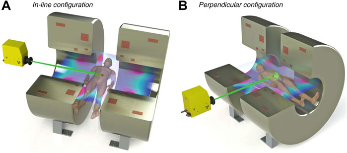
FIGURE 1. Diagram showing the MRI-LINAC orientations. In (A), the in-line orientation is shown; in (B), the perpendicular orientation is shown. Figure adapted from MRI for radiotherapy by Whelan et al. [41].
The two current in-line MRI-LINAC systems, the Australian MRI-LINAC [4,46] and the Aurora-RT system (MagnetTx Oncology Solutions, Edmonton, Alberta, Canada) [3] are both preclinical systems, though the Australian MRI-LINAC has been commissioned and approved for use under a clinical trial. The Australian MRI-LINAC uses a 1 T open bore MRI scanner and a 6 MV LINAC fitted with a clinical multileaf collimator (MLC), with the LINAC and MLC mounted on rails to allow for variable source-isocentre distances. For the Australian MRI-LINAC, a significant fringe magnetic field permeates upstream of isocentre towards the LINAC. The focusing of contaminant electrons is significant, and leads to high entrance doses along the central axis [45,47,48]. The Aurora-RT system uses a 0.6 T bi-planar open bore MRI scanner and a 6 MV LINAC [3]. In the Aurora-RT system, an iron yoke magnetically shields the LINAC from the MRI scanner’s fringe fields, thereby reducing the focusing of contaminant electrons upstream of isocentre; increases in entrance doses have been reported for the Aurora-RT system [49,50], though these increases are much less severe than those that occur with the Australian MRI-LINAC.
For MRI-LINACs with the photon beam orientated perpendicular to the magnetic field (referred to as perpendicular MRI-LINACs or transverse MRI-LINACs in the literature; shown in Figure 1B), the Lorentz force is imparted orthogonal to both the photon beam and the magnetic field. As a result, the charged particles are focused laterally and tend to follow circular trajectories [1,51]. At the macroscopic level, this causes the off-axis dose distributions to become skewed asymmetrically, the dose kernel to shift laterally and the penetration depth to decrease. Additionally, there is the potential for increased doses at interfaces between low density media and high density media (such as air-tissue interfaces) [1]. This increase in dose occurs as the electrons can exit the high density media, gyrate 180° in the low density media and penetrate the high density media. This effect has been termed as the electron return effect (ERE).
The two current perpendicular MRI-LINAC systems, the Elekta Unity (Elekta Instrument AB, Stockholm, Sweden) [1,52] and the ViewRay MRIdian (ViewRay Inc., Oakwood, Ohio, United States) are both clinical systems [5,53,54]. The Elekta Unity consists of a 1.5 T wide bore MRI scanner and a 7 MV LINAC. Initial installations of the ViewRay MRIdian consisted of a 0.35 T split bore MRI scanner and 3 60Co sources [5]; more recently, newer installations of the ViewRay MRIdian system consist of a 0.35 T split bore MRI scanner and a 6 MV LINAC [54].
Dosimeter Perturbations
Dosimeter perturbations can arise from multiple sources. Many dosimeters experience changes in sensitivity in the presence of strong magnetic fields [7,55,56]. Dosimeters that have angular or orientation dependent sensitivities can be brought into effect by the curved trajectories followed by charged particles [57,58]. The characteristics and severity of such dependence and change in sensitivity are specific to each dosimeter, being influenced by sensitive volume size [14,15], geometry [11,13], density [14,15] and by any high Z extracameral components [14,15]. The physics responsible for the sensitivity dependence are influenced by experimental factors such as magnetic field strength [11,15], MRI-LINAC orientation [7,59], orientation of the dosimeter with respect to the photon beam [11,12,15], beam quality [12,13] and field size [14], hence the dosimeter’s sensitivity dependence also vary with these factors. Additionally, the presence of small air gaps around a dosimeter’s sensitive volume can cause non-negligible perturbations to the measured response, making the measured responses deviate from the expected dose in water [16,17,60]. Detector and setup specific correction factors are required to correct the calibration of dosimeters for reference dosimetry with MRI-LINACs [12,14,15,56,59].
When performing dosimetry, the introduction of a dosimeter into a water volume perturbs the electron fluence in water at the volume occupied by the dosimeter [15]. The severity of such electron fluence perturbations depends on the dosimeter’s size, its physical and electron densities, and its photonic and electronic interaction coefficients [15]; electron fluence perturbations are also setup specific [14,15]. Such perturbations are problematic given dosimeters are typically calibrated for absorbed dose to water no magnetic field present [61], and contributes to a dosimeter’s energy dependence with MRI-LINACs. Dosimeters comprised of water equivalent materials with matching densities and interaction coefficients to those of water, such as entirely plastic FODs are theoretically immune to such perturbations [15].
The strong magnetic fields influence the trajectories of charged particles, causing dosimeters to experience a shift in their effective point of measurement (EPOM) compared to their EPOM with no magnetic field present [12,43,57,62]. In perpendicular magnetic fields, dosimeters experience EPOM shifts that are directed both laterally and depth-wise [43]; in in-line magnetic fields, dosimeters experience EPOM shifts that are directed depth-wise only [43]. The magnitude of such shifts increase as sensitive volume density decreases. Consequently, dosimeters with sensitive volumes that are less dense than water (e.g. ionisation chambers) experience more severe EPOM shifts than those theoretically experienced by equivalent volumes of water [43,57]. Conversely, dosimeters with sensitive volumes that are more dense than water (e.g. semiconductor and diamond detectors) experience less severe EPOM shifts than those theoretically experienced by equivalent volumes of water [43,57]. As a result, non water-equivalent dosimeters measured dose distributions can deviate from the expected dose distributions deposited in water [43,57].
Fibre Optic Dosimeter Studies With MRI-LINAC
Numerous studies have investigated the magnetic field dependence of many plastic scintillators with radioactive sources in the scope of hadron calorimetry. Bloemker et al. [18] irradiated three plastic scintillators with 25 MeV protons, 5.9 keV X-rays and UV light for magnetic fields with strengths up to 0.45 T. Increases in light output were observed independent of the magnetic field direction and orientation; a 3.3% increase in light output was observed for a polyvinyl toluene and polystyrene based scintillators, and a greater increase in response was reported for a PMMA based scintillator. Green et al. [19] and Bertoldi et al. [20] irradiated several plastic scintillators with 226Ra α sources, 137Cs β sources and 60Co γ sources in magnetic fields with strengths up to 20 T. All scintillators exhibited increasing light outputs up to 2 T ranging between 6% and 8%, and a plateau in light output above 2.0 T; this was dependent on the plastic scintillator’s base material and independent of radiation source [19,20]. The authors concluded that the scintillation mechanism was not affected by strong magnetic fields, and that the increased light output per unit absorbed dose arose from changes in the spatial distribution of energy depositions at a microscopic level [19,20].
Several groups have characterised how the response of FODs were affected by magnetic fields using conventional LINACs and external magnets. Stefanowicz et al. investigated two in-house FODs using a conventional LINAC and a perpendicular magnetic field and reported asymmetric behaviour that could not be explained [63]. In their study, they reported a maximum 7% increase in relative response at +0.8 T (relative to the response in the 0 T field), and a maximum 3.8% increase in relative response at −0.8 T (relative to the response in the 0 T field). It should be noted that the stem correction method employed assumed that the ratio of stem signal to luminescence remained constant, independent of magnetic field strength. Therriault-Proulx et al. investigated an in-house FOD and a commercial FOD using a conventional LINAC and perpendicular magnetic field [64], similar to Stefanowicz et al. [63]. In this study, the FOD’s stem corrected responses were compared against their raw, uncorrected responses. With the stem signals corrected by Chromatic Removal, a maximum increase of 2.4% was reported for a 1.5 T field (relative to the corrected response at 0 T). The authors concluded that this behaviour had arisen with an increase in the dose deposited in the scintillator, caused by the electron’s curved trajectories. With no stem correction applied, the FOD’s raw responses experienced a maximum increase of 20% relative to the raw response at 0 T. The authors suggested that the asymmetric behaviour reported by Stefanowicz et al. [63] had arisen as their stem correction method was not suitable for use in the perpendicular MRI-LINAC setup.
Simiele et al. investigated the accuracy of several stem correction methods with an in-house FOD using a conventional LINAC and a perpendicular magnetic field (generated by an electromagnet) [65]. In their study, Background Subtraction corrected responses experienced asymmetric behaviour similar to that reported by Stefanowicz et al. [63]: the Background Subtraction responses experienced a maximum increase in response of 5.5% at +1.4 T and a maximum increase in response of 2.5% at -1.4 T (relative to the background subtraction corrected responses at 0 T). Symmetric behaviour was expected for their entirely plastic FOD given the FOD was positioned in the centre of the radiation field, its direct water equivalence and its symmetrical geometry. Theoretically, for the small, entirely plastic FODs set up along the central axis in a water phantom, the FODs should exhibit symmetric behaviour with respect to magnetic field polarity due to their direct water equivalence, minimal perturbation of radiation beam in water and their intrinsic angular independent response. Simiele et al. concluded that Background Subtraction was suboptimal for applications with perpendicular MRI-LINACs [65]. For Chromatic Removal, symmetric behaviour was reported, though there was a 4% maximum increase in the corrected response relative to their corresponding responses at 0 T. Simiele et al. concluded that Chromatic Removal methods were more suitable for application with perpendicular MRI-LINACs [65]. The aforementioned studies, as well as studies by Maraghechi et al. [66] and Simiele et al. [67] highlight that accurate stem correction methods are important in ensuring the FODs remain accurate for dosimetry with MRI-LINACs.
Yoon et al. investigated the angular and field size dependence of the commercial FOD, Exradin W1 (Standard Imaging, United States) for MRI-LINAC dosimetry with a 0.35 T perpendicular MRI-LINAC [68]. Chromatic Removal was applied to correct the stem signal for all measurements in this study. The Exradin W1 FOD had negligible angular dependencies, with all measurements within 1% of the response at 0° in the presence of the 0.35 T field. For square fields with side lengths ≤10.5 cm, negligible field size dependences were observed. However, for square fields with side lengths
Madden et al. applied an in-house FOD (using a plastic scintillator) with the Australian MRI-LINAC to measure output factors along the central axis [69], beam profiles along the cross-plane axis [70] and percent depth dose distributions (PDDs) along the central axis [71]. For each set of measurements, the FOD was orientated perpendicular to the magnetic field, with a bare optical fibre downstream of the FOD. Background Subtraction was applied to correct the stem signals for all measurements. FOD measured output factors and beam profiles were generally within agreement of reference data. For depths beyond the classical depth of maximum dose, the FOD measured PDDs were generally within agreement of reference data. A systematic disagreement was reported between the FOD and reference PDD for the 2.6 cm × 2.6 cm field size that could not be explained, though there was the potential for detector misalignment in the small field. Unacceptable disagreements were reported between the FOD and reference PDDs in the entrance region of the PDDs, arising due to a combination of volume averaging and poor performance of the background subtraction stem correction method in the high spatial dose gradients in the entrance region of these PDDs. The collective results from this set of studies supported that FODs using plastic scintillators were generally well-suited for relative MRI-LINAC dosimetry in most measurement conditions, and it was recommended that a FOD should be investigated prior to clinical use to ensure that it remains accurate in the desired measurement conditions.
Cusumano et al. characterised a commercial FOD using an inorganic scintillator (DoseWire Series 2000, DoseVue, Belgium) for dosimetry with a 0.35 T perpendicular MRI-LINAC [72]. The commercial FOD’s relative response was demonstrated to be orientation independent, irradiation angle independent, stable with temperature, repeatable within 1% and stable during real-time measurements. The inorganic FOD’s output factors remained within 1% of reference measurements with field sizes between 0.83 × 0.83 cm and 12.45 × 12.45 cm. Additionally, the PDD measured at 3.32 × 3.32 cm remained within 1% of the reference PDDs. However, the inorganic FOD’s PDD deviated from the reference PDD in the 9.96 × 9.96 cm field, owing to an energy dependence of the inorganic FOD. The authors concluded that the DoseWire Series 2000 was particularly effective for small-field dosimetry and promising for in-vivo dose measurements.
Discussion: Challenges and Opportunities
Challenges
Accurate stem correction is vital for ensuring that FODs are accurate with MRI-LINACs. In studies with perpendicular MRI-LINACs, Background Subtraction has been reported to be suboptimal as its requirement that the FOD and bare optical fibre receive matching irradiations cannot be ensured [65]. Chromatic Removal avoids such constraints and has been demonstrated suitable for use during MRI-LINAC dosimetry.
In response to low energy electrons, scintillators experience a decrease in scintillation output and under-estimate the dose deposited in the scintillator [73]. This effect is not typically significant during megavoltage photon and electron beam dosimetry with LINACs [73], however it may be significant in specific circumstances with MRI-LINACs. For perpendicular MRI-LINACs, measurements near air-phantom interfaces may be prone to significant fluences of low energy electrons due to the electron return effect. For in-line MRI-LINACs, near-surface measurements along the central axis are prone to significant fluences of low energy electrons due to the electron focusing effect [48]. Further measurements in these conditions are required to determine the degree to which FODs are affected, and whether or not corrections are required in the desired conditions.
Energy dependence is common for FODs using inorganic scintillators. The energy dependence of a scintillator is tied to the scintillator’s chemical composition, thus it is material dependent. Corrections for energy dependence are necessary for ensuring that inorganic scintillators are accurate in the measurement of absorbed dose to water, and must be characterised prior to the application of FODs using inorganic scintillators for MRI-LINAC dosimetry [72].
Opportunities
Ionisation chambers and calibrated dosimeters require correction factors to account for changes in their absolute dose sensitivity arising from the presence of the magnetic fields. From the studies investigating a plastic scintillator’s dependence on magnetic field strength, it appears as though the scintillation response is insensitive to magnetic fields and dependent only on the physical dose deposited in their volume provided the stem correction remains accurate. For FODs using plastic scintillators, their direct water equivalence, near-correctionless properties and insensitivity with respect to magnetic fields should allow for the direct measurement of detector specific correction factors with MRI-LINACs.
There are currently a lack of instruments capable of validating MR guided treatments with MRI-LINACs through in vivo dosimetry [74,75]; this includes suitable anthropomorphic phantoms and real-time dosimeters that do not distort the MRI’s magnetic field. Many common dosimeters are comprised of materials such as graphite or metals that distort the MRI’s magnetic field, inducing image artifacts [76,77]. Dosimeters comprised of non-ferromagnetic materials can reduce and eliminate such distortions, making them advantageous for in vivo verification of MR guided treatments. Entirely plastic FODs, i.e. FODs comprised of plastic scintillators and plastic optical fibres do not the distort the MRI’s magnetic field given their favourable chemical composition, typically small sizes, and passive optical response [78]. Further, the entirely plastic FODs inherit high temporal resolution and real-time responses from their scintillators. In previous studies, entirely plastic FODs have successfully been applied for time-resolved dosimetry in a dynamic thorax phantom during LINAC treatments [79–81] and for in vivo dosimetry in an anthropomorphic phantom [82]. Recently, two in-house, entirely plastic FODs were demonstrated accurate and successful for time-resolved dosimetric verification of gated MR guided treatments using a dynamic phantom [78]. Entirely plastic FODs are expected to be crucial in clinical dosimetric verifications of MR guided treatments. It is anticipated that other highly specialised dosimeters such as the MOSFET [83] and MoSkin detector [48] will also be suitable for in vivo measurements [83].
Conclusion
There has been increasing interest in the use of FODs for dosimetry with MRI-LINACs, owing to their unique combination of advantageous dosimetric qualities. Such a set of qualities makes FODs attractive for general dosimetry measurements with MRI-LINACs, as well as for the direct measurement of detector specific correction factors for other dosimeters. Given the FOD’s real-time responses in high temporal resolutions, entirely plastic FODs appear promising for time-resolved in vivo dosimetry with MRI-LINACs. Accurate stem correction remains imperative in ensuring that FOD’s responses are degraded by stem signals.
Author Contributions
LM wrote the first draft of the manuscript. All authors contributed to manuscript revision, read and approved the submitted version.
Funding
The Australian MRI-LINAC program is supported by the Australian NHMRC Program Grant APP1132471 and Cancer Council NSW, Grant Number: APP1128336. LM received scholarship support from the South West Sydney Local Health District and the Australian Government Research Training Program.
Conflict of Interest
The authors declare that the research was conducted in the absence of any commercial or financial relationships that could be construed as a potential conflict of interest.
Publisher’s Note
All claims expressed in this article are solely those of the authors and do not necessarily represent those of their affiliated organizations, or those of the publisher, the editors and the reviewers. Any product that may be evaluated in this article, or claim that may be made by its manufacturer, is not guaranteed or endorsed by the publisher.
References
1. Raaijmakers AJE, Raaymakers BW, Lagendijk JJW. Integrating a MRI Scanner with a 6 MV Radiotherapy Accelerator: Dose Increase at Tissue-Air Interfaces in a Lateral Magnetic Field Due to Returning Electrons. Phys Med Biol (2005) 50:1363–76. doi:10.1088/0031-9155/50/7/002
2. Lagendijk JJW, Raaymakers BW, Raaijmakers AJE, Overweg J, Brown KJ, Kerkhof EM, et al. Mri/linac Integration. Radiother Oncol (2008) 86:25–9. doi:10.1016/j.radonc.2007.10.034
3. Fallone BG. The Rotating Biplanar Linac-Magnetic Resonance Imaging System. Semin Radiat Oncol (2014) 24:200–2. doi:10.1016/j.semradonc.2014.02.011
4. Keall PJ, Barton M, Crozier S. The Australian Magnetic Resonance Imaging-Linac Program. Semin Radiat Oncol (2014) 24:203–6. doi:10.1016/j.semradonc.2014.02.015
5. Mutic S, Dempsey JF. The ViewRay System: Magnetic Resonance-Guided and Controlled Radiotherapy. Semin Radiat Oncol (2014) 24:196–9. doi:10.1016/j.semradonc.2014.02.008
6. Kerkmeijer LGW, Fuller CD, Verkooijen HM, Verheij M, Choudhury A, Harrington KJ, et al. The MRI-Linear Accelerator Consortium: Evidence-Based Clinical Introduction of an Innovation in Radiation Oncology Connecting Researchers, Methodology, Data Collection, Quality Assurance, and Technical Development. Front Oncol (2016) 6:215. doi:10.3389/fonc.2016.00215
7. Meijsing I, Raaymakers BW, Raaijmakers AJE, Kok JGM, Hogeweg L, Liu B, et al. Dosimetry for the Mri Accelerator: The Impact of a Magnetic Field on the Response of a Farmer Ne2571 Ionization Chamber. Phys Med Biol (2009) 54:2993–3002. doi:10.1088/0031-9155/54/10/002
8. Liney GP, Whelan B, Oborn B, Barton M, Keall P. MRI-linear Accelerator Radiotherapy Systems. Clin Oncol (2018) 30:686–91. doi:10.1016/j.clon.2018.08.003
9. Raaymakers BW, Raaijmakers AJE, Kotte ANTJ, Jette D, Lagendijk JJW. Integrating a MRI Scanner with a 6 MV Radiotherapy Accelerator: Dose Deposition in a Transverse Magnetic Field. Phys Med Biol (2004) 49:4109–18. doi:10.1088/0031-9155/49/17/019
10. Jelen U, Begg J. Dosimetry Needs for MRI-Linacs. J Phys Conf Ser (2019) 1305:012010. doi:10.1088/1742-6596/1305/1/012010
11. Pojtinger S, Dohm OS, Kapsch R-P, Thorwarth D. Ionization Chamber Correction Factors for MR-Linacs. Phys Med Biol (2018) 63:11NT03. doi:10.1088/1361-6560/aac4f2
12. O'Brien DJ, Roberts DA, Ibbott GS, Sawakuchi GO. Reference Dosimetry in Magnetic fields: Formalism and Ionization Chamber Correction Factors. Med Phys (2016) 43:4915–27. doi:10.1118/1.4959785
13. Malkov VN, Rogers DWO. Sensitive Volume Effects on Monte Carlo Calculated Ion Chamber Response in Magnetic fields. Med Phys (2017) 44:4854–8. doi:10.1002/mp.12421
14. Cervantes Y, Duchaine J, Billas I, Duane S, Bouchard H. Monte Carlo Calculation of Detector Perturbation and Quality Correction Factors in a 1.5 T Magnetic Resonance Guided Radiation Therapy Small Photon Beams. Phys Med Biol (2021) 66:225004. doi:10.1088/1361-6560/ac3344
15. Cervantes Y, Duane S, Bouchard H. Monte Carlo Investigation of Electron Fluence Perturbation in MRI Guidedradiotherapy Beams Using Six Commercial Radiation Detectors. Phys Med Biol (2022) 67:035001. doi:10.1088/1361-6560/ac4b36
16. Hackett SL, van Asselen B, Wolthaus JWH, Kok JGM, Woodings SJ, Lagendijk JJW, et al. Consequences of Air Around an Ionization Chamber: Are Existing Solid Phantoms Suitable for Reference Dosimetry on an MR-LINAC? Med Phys (2016) 43:3961–8. doi:10.1118/1.4952727
17. Agnew J, O’Grady F, Young R, Duane S, Budgell GJ. Quantification of Static Magnetic Field Effects on Radiotherapy Ionization chambers. Phys Med Biol (2017) 62:1731–43. doi:10.1088/1361-6560/aa5876
18. Bloemker D, Holm U, Klanner R, Krebs B. Plastic Scintillators in Magnetic fields. Nucl Instrum Meth A (1992) 311:505–11. doi:10.1016/0168-9002(92)90648-N
19. Green D, Ronzhin A, Hagopian V. Magnetic fields and Scintillator Performance (1995). doi:10.2172/87823
20. Bertoldi M, Green DR, Hagopian V, Marraffino J, Ronzhin A, Thomaston J. Scintillators in Magnetic fields up to 20 T. Nucl Instr Methods Phys Res Section A: Acc Spectrometers, Detectors Associated Equipment (1997) 386:301–6. doi:10.1016/S0168-9002(96)01178-3
21. Beddar AS, Mackie TR, Attix FH. Water-equivalent Plastic Scintillation Detectors for High-Energy Beam Dosimetry: I. Physical Characteristics and Theoretical Considerations. Phys Med Biol (1992) 37:1883–900. doi:10.1088/0031-9155/37/10/006
22. Andersen CE, Damkjær SMS, Kertzscher G, Greilich S, Aznar MC. Fiber-coupled Radioluminescence Dosimetry with Saturated Al 2 O 3 :C Crystals: Characterization in 6 and 18 MV Photon Beams. Radiat Measurements (2011) 46:1090–8. doi:10.1016/j.radmeas.2011.06.063
23. Beaulieu L, Beddar S. Review of Plastic and Liquid Scintillation Dosimetry for Photon, Electron, and Proton Therapy. Phys Med Biol (2016) 61:R305–R343. doi:10.1088/0031-9155/61/20/R305
24. Clift MA, Sutton RA, Webb DV. Water Equivalence of Plastic Organic Scintillators in Megavoltage Radiotherapy Bremsstrahlung Beams. Phys Med Biol (2000) 45:1885–95. doi:10.1088/0031-9155/45/7/313
25. Archer J, Li E, Davis J, Cameron M, Rosenfeld A, Lerch M. High Spatial Resolution Scintillator Dosimetry of Synchrotron Microbeams. Sci Rep (2019) 9. doi:10.1038/s41598-019-43349-6
26. Jelley JV. Cerenkov Radiation and its Applications. Br J Appl Phys (1955) 6:227–32. doi:10.1088/0508-3443/6/7/301
27. Beddar AS, Mackie TR, Attix FH. Cerenkov Light Generated in Optical Fibres and Other Light Pipes Irradiated by Electron Beams. Phys Med Biol (1992) 37:925–35. doi:10.1088/0031-9155/37/4/007
28. Jang K, Shin S, Kim S, Kim J, Yoo W, Ji Y, et al. Measurement of Cerenkov Radiation Induced by the Gamma-Rays of Co-60 Therapy Units Using Wavelength Shifting Fiber. Sensors (2014) 14:7013–25. doi:10.3390/s140407013
29. Lambert J, Yin Y, McKenzie DR, Law S, Suchowerska N. Cerenkov-free Scintillation Dosimetry in External Beam Radiotherapy with an Air Core Light Guide. Phys Med Biol (2008) 53:3071–80. doi:10.1088/0031-9155/53/11/021
30. Darafsheh A, Melzer JE, Harrington JA, Kassaee A, Finlay JC. Radiotherapy Fiber Dosimeter Probes Based on Silver-Only Coated Hollow Glass Waveguides. J Biomed Opt (2018) 23:1–7. doi:10.1117/1.JBO.23.1.015006
31. Archer J, Madden L, Li E, Wilkinson D, Rosenfeld AB. An Algorithmic Approach to Single‐probe Cherenkov Removal in Pulsed X‐ray Beams. Med Phys (2019) 46:1833–9. doi:10.1002/mp.13383
32. Madden L, Archer J, Li E, Wilkinson D, Rosenfeld A. Temporal Separation of Cerenkov Radiation and Scintillation Using Artificial Neural Networks in Clinical LINACs. Physica Med (2018) 54:131–6. doi:10.1016/j.ejmp.2018.10.007
33. Madden L, Archer J, Li E, Wilkinson D, Rosenfeld A. Temporal Separation of Cerenkov Radiation and Scintillation Using a Clinical LINAC and Artificial Intelligence. Phys Med Biol (2018) 63:225004. doi:10.1088/1361-6560/aae938
34. Guillot M, Gingras L, Archambault L, Beddar S, Beaulieu L. Spectral Method for the Correction of the Cerenkov Light Effect in Plastic Scintillation Detectors: A Comparison Study of Calibration Procedures and Validation in Cerenkov Light-Dominated Situations. Med Phys (2011) 38:2140–50. doi:10.1118/1.3562896
35. Beierholm AR, Behrens CF, Andersen CE. Dosimetric Characterization of the Exradin W1 Plastic Scintillator Detector through Comparison with an In-House Developed Scintillator System. Radiat Measurements (2014) 69:50–6. doi:10.1016/j.radmeas.2014.08.005
36. Boer SFd., Beddar AS, Rawlinson JA. Optical Filtering and Spectral Measurements of Radiation-Induced Light in Plastic Scintillation Dosimetry. Phys Med Biol (1993) 38:945–58. doi:10.1088/0031-9155/38/7/005
37. Dimitriadis A, Patallo IS, Billas I, Duane S, Nisbet A, Clark CH. Characterisation of a Plastic Scintillation Detector to Be Used in a Multicentre Stereotactic Radiosurgery Dosimetry Audit. Radiat Phys Chem (2017) 140:373–8. doi:10.1016/j.radphyschem.2017.02.023
38. Beddar AS, Mackie TR, Attix FH. Water-equivalent Plastic Scintillation Detectors for High-Energy Beam Dosimetry: II. Properties and Measurements. Phys Med Biol (1992) 37:1901–13. doi:10.1088/0031-9155/37/10/007
39. Archambault L, Beddar AS, Gingras L, Roy R, Beaulieu L. Measurement Accuracy and Cerenkov Removal for High Performance, High Spatial Resolution Scintillation Dosimetry. Med Phys (2005) 33:128–35. doi:10.1118/1.2138010
40. Fontbonne JM, Iltis G, Ban G, Battala A, Vernhes JC, Tillier J, et al. Scintillating Fiber Dosimeter for Radiation Therapy Accelerator. IEEE Trans Nucl Sci (2002) 49:2223–7. doi:10.1109/TNS.2002.803680
41. Whelan B, Oborn B, Liney G, Keall P. MRI Linac Systems. Berlin, Germany: Springer International Publishing (2019). p. 155–68. doi:10.1007/978-3-030-14442-5_10
42. Reynolds M, Fallone BG, Rathee S. Dose Response of Selected Ion chambers in Applied Homogeneous Transverse and Longitudinal Magnetic fields. Med Phys (2013) 40:042102. doi:10.1118/1.4794496
43. Looe HK, Delfs B, Poppinga D, Harder D, Poppe B. Magnetic Field Influences on the Lateral Dose Response Functions of Photon-Beam Detectors: MC Study of wall-less Water-Filled Detectors with Various Densities. Phys Med Biol (2017) 62:5131–48. doi:10.1088/1361-6560/aa6ca0
44. Oborn BM, Metcalfe PE, Butson MJ, Rosenfeld AB, Keall PJ. Electron Contamination Modeling and Skin Dose in 6 Mv Longitudinal Field Mrigrt: Impact of the Mri and Mri Fringe Field. Med Phys (2012) 39:874–90. doi:10.1118/1.3676181
45. Liney GP, Dong B, Begg J, Vial P, Zhang K, Lee F, et al. Technical Note: Experimental Results from a Prototype High-Field Inline MRI-Linac. Med Phys (2016) 43:5188–94. doi:10.1118/1.4961395
46. Jelen U, Dong B, Begg J, Roberts N, Whelan B, Keall P, et al. Dosimetric Optimization and Commissioning of a High Field Inline Mri-Linac. Front Oncol (2020) 10. doi:10.3389/fonc.2020.00136
47. Begg J, Alnaghy SJ, Causer T, Alharthi T, George A, Glaubes L, et al. Technical Note: Experimental Characterization of the Dose Deposition in Parallel MRI‐linacs at Various Magnetic Field Strengths. Med Phys (2019) 46:5152–8. doi:10.1002/mp.13767
48. Roberts NF, Patterson E, Jelen U, Causer T, Holloway L, Liney G, et al. Experimental Characterization of Magnetically Focused Electron Contamination at the Surface of a High‐field Inline MRI‐linac. Med Phys (2019) 46:5780–9. doi:10.1002/mp.13847
49. Ghila A, Steciw S, Fallone BG, Rathee S. Experimental Verification of Egsnrc Monte Carlo Calculated Depth Doses within a Realistic Parallel Magnetic Field in a Polystyrene Phantom. Med Phys (2017) 44:4804–15. doi:10.1002/mp.12413
50. Ghila A, Fallone BG, Rathee S. Technical Note: Experimental Verification of EGS Nrc Calculated Depth Dose within a Parallel Magnetic Field in a Lung Phantom. Med Phys (2018) 45:5653–8. doi:10.1002/mp.13215
51. Raaijmakers AJE, Raaymakers BW, Lagendijk JJW. Experimental Verification of Magnetic Field Dose Effects for the MRI-Accelerator. Phys Med Biol (2007) 52:4283–91. doi:10.1088/0031-9155/52/14/017
52. Raaymakers BW, Jürgenliemk-Schulz IM, Bol GH, Glitzner M, Kotte ANTJ, van Asselen B, et al. First Patients Treated with a 1.5 T MRI-Linac: Clinical Proof of Concept of a High-Precision, High-Field MRI Guided Radiotherapy Treatment. Phys Med Biol (2017) 62:L41–L50. doi:10.1088/1361-6560/aa9517
53. Acharya S, Fischer-Valuck BW, Kashani R, Parikh P, Yang D, Zhao T, et al. Online Magnetic Resonance Image Guided Adaptive Radiation Therapy: First Clinical Applications. Int J Radiat Oncol Biol Phys (2016) 94:394–403. doi:10.1016/j.ijrobp.2015.10.015
54. Klüter S. Technical Design and Concept of a 0.35 T Mr-Linac. Clin Translational Radiat Oncol (2019) 18:98–101. doi:10.1016/j.ctro.2019.04.007
55. Spindeldreier CK, Schrenk O, Bakenecker A, Kawrakow I, Burigo L, Karger CP, et al. Radiation Dosimetry in Magnetic fields with Farmer-type Ionization chambers: Determination of Magnetic Field Correction Factors for Different Magnetic Field Strengths and Field Orientations. Phys Med Biol (2017) 62:6708–28. doi:10.1088/1361-6560/aa7ae4
56. de Prez L, Woodings S, de Pooter J, van Asselen B, Wolthaus J, Jansen B, et al. Direct Measurement of Ion Chamber Correction Factors, kQ and kB, in a 7 MV MRI-Linac. Phys Med Biol (2019) 64:105025. doi:10.1088/1361-6560/ab1511
57. O'Brien DJ, Dolan J, Pencea S, Schupp N, Sawakuchi GO. Relative Dosimetry with an MR-LINAC: Response of Ion chambers, diamond, and Diode Detectors for off-axis, Depth Dose, and Output Factor Measurements. Med Phys (2018) 45:884–97. doi:10.1002/mp.12699
58. Woodings SJ, Wolthaus JWH, van Asselen B, de Vries JHW, Kok JGM, Lagendijk JJW, et al. Performance of a PTW 60019 microDiamond Detector in a 1.5 T MRI-LINAC. Phys Med Biol (2018) 63:05NT04. doi:10.1088/1361-6560/aaa1c6
59. de Pooter J, Billas I, de Prez L, Duane S, Kapsch R-P, Karger CP, et al. Reference Dosimetry in MRI-Linacs: Evaluation of Available Protocols and Data to Establish a Code of Practice. Phys Med Biol (2021) 66:05TR02. doi:10.1088/1361-6560/ab9efe
60. O'Brien DJ, Sawakuchi GO. Monte Carlo Study of the Chamber-Phantom Air gap Effect in a Magnetic Field. Med Phys (2017) 44:3830–8. doi:10.1002/mp.12290
61.IAE. Absorbed Dose Determination in External Beam Radiotherapy. No. 398 in Technical Reports Series. Vienna: International Atomic Energy Agency (2001).
62. Smit K, van Asselen B, Kok JGM, Aalbers AHL, Lagendijk JJW, Raaymakers BW. Towards Reference Dosimetry for the MR-LINAC: Magnetic Field Correction of the Ionization Chamber reading. Phys Med Biol (2013) 58:5945–57. doi:10.1088/0031-9155/58/17/5945
63. Stefanowicz S, Latzel H, Lindvold LR, Andersen CE, Jäkel O, Greilich S. Dosimetry in Clinical Static Magnetic fields Using Plastic Scintillation Detectors. Radiat Measurements (2013) 56:357–60. doi:10.1016/j.radmeas.2013.03.012
64. Therriault-Proulx F, Wen Z, Ibbott G, Beddar S. Effect of Magnetic Field Strength on Plastic Scintillation Detector Response. Radiat measurements (2018) 116:10–3. doi:10.1016/j.radmeas.2018.06.011
65. Simiele E, Kapsch R-P, Ankerhold U, Culberson W, Dewerd L. Spectral Characterization of Plastic Scintillation Detector Response as a Function of Magnetic Field Strength. Phys Med Biol (2018) 63:085001. doi:10.1088/1361-6560/aab56c
66. Maraghechi B, Hao Y, Hong S, Li H, Mutic S, Darafsheh A. Effect of External Magnetic Field on the Collected Cherenkov Radiation by Fiber Optic Dosimeters. In: BW Pogue, editor. Optics and Ionizing Radiation. International Society for Optics and Photonics (SPIE), Vol. 11224 (2020). p. 37–41. doi:10.1117/12.2543246
67. Simiele E, Viscariello N, DeWerd L. Monte Carlo Modeling of the Influence of strong Magnetic fields on the Stem‐effect in Plastic Scintillation Detectors Used in Radiotherapy Dosimetry. Med Phys (2021) 48:1381–94. doi:10.1002/mp.14637
68. Yoon J, Kim JI, Choi CH, Park JM. Characteristics of the Exradin W1 Scintillator in the Magnetic Field. J Appl Clin Med Phys (2019) 20:149–56. doi:10.1002/acm2.12707
69. Madden L, Archer J, Li E, Jelen U, Dong B, Roberts N, et al. First Measurements with a Plastic Scintillation Dosimeter at the Australian MRI-LINAC. Phys Med Biol (2019) 64:175015. doi:10.1088/1361-6560/ab324b
70. Madden L, Archer J, Li E, Jelen U, Dong B, Holloway L, et al. MRI-LINAC Beam Profile Measurements Using a Plastic Scintillation Dosimeter. Physica Med (2020) 73:111–6. doi:10.1016/j.ejmp.2020.04.016
71. Madden L, Roberts N, Jelen U, Dong B, Holloway L, Metcalfe P, et al. In-line MRI-LINAC Depth Dose Measurements Using an In-House Plastic Scintillation Dosimeter. Biomed Phys Eng Express (2021) 7:025012. doi:10.1088/2057-1976/abe295
72. Cusumano D, Placidi L, D'Agostino E, Boldrini L, Menna S, Valentini V, et al. Characterization of an Inorganic Scintillator for Small‐field Dosimetry in MR‐guided Radiotherapy. J Appl Clin Med Phys (2020) 21:244–51. doi:10.1002/acm2.13012
73. Santurio GV, Andersen CE. Quantifying the Ionization Quenching Effect in Organic Plastic Scintillators Used in Mv Photon Dosimetry. Radiat Measurements (2019) 129:106200. doi:10.1016/j.radmeas.2019.106200
74. Corradini S, Alongi F, Andratschke N, Belka C, Boldrini L, Cellini F, et al. Mr-guidance in Clinical Reality: Current Treatment Challenges and Future Perspectives. Radiat Oncol (2019) 14:19. doi:10.1186/s13014-019-1308-y
75. Weidner A, Stengl C, Dinkel F, Dorsch S, Murillo C, Seeber S, et al. An Abdominal Phantom with Anthropomorphic Organ Motion and Multimodal Imaging Contrast for Mr-Guided Radiotherapy. Phys Med Biol (2022) 67:045009. doi:10.1088/1361-6560/ac4ef8
76. Stadler A, Schima W, Ba-Ssalamah A, Kettenbach J, Eisenhuber E. Artifacts in Body Mr Imaging: Their Appearance and How to Eliminate Them. Eur Radiol (2007) 17:1242–55. doi:10.1007/s00330-006-0470-4
77. Choudhri AF, Patel BJ, Phillips ME, Mills KA, Whitehead MT, Fleming JC. Diamagnetic Susceptibility Artifact Associated with Graphite Foreign Body of the Orbit. Ophthalmic Plast Reconstr Surg (2013) 29:e105–e107. doi:10.1097/IOP.0b013e31827df017
78. Klavsen MF, Ankjærgaard C, Behrens CP, Vogelius IR, Boye K, Hansen RH, et al. Time-resolved Plastic Scintillator Dosimetry in Mr Linear Accelerators without Image Distortion. Radiat Measurements (2022) 154:106759. doi:10.1016/j.radmeas.2022.106759
79. Beierholm AR, Andersen CE, Lindvold LR, Kjær-Kristoffersen F, Medin J. A Comparison of Bcf-12 Organic Scintillators and Al2o3:c Crystals for Real-Time Medical Dosimetry. Radiat Measurements (2008) 43:898–903. doi:10.1016/j.radmeas.2007.12.032
80. Beierholm AR, Behrens CF, Andersen CE. Studying the Potential of point Detectors in Time-Resolved Dose Verification of Dynamic Radiotherapy. Radiat Measurements (2015) 82:129–37. doi:10.1016/j.radmeas.2015.09.007
81. Sibolt P, Andersen CE, Ottosson W, Behrens CF. Time-resolved Plastic Scintillator Dosimetry in a Dynamic Thorax Phantom. Radiat Measurements (2017) 106:373–7. doi:10.1016/j.radmeas.2017.04.016
82. Archambault L, Briere TM, Pönisch F, Beaulieu L, Kuban DA, Lee A, et al. Toward a Real-Time In Vivo Dosimetry System Using Plastic Scintillation Detectors. Int J Radiat Oncol Biol Phys (2010) 78:280–7. doi:10.1016/j.ijrobp.2009.11.025
Keywords: fibre-optics, scintillators, luminescence, MRI-LINACs, dosimetry
Citation: Madden L, Holloway L, Rosenfeld A and Li E (2022) Fibre-Optic Dosimetry for MRI-LINACs: A Mini-Review. Front. Phys. 10:879624. doi: 10.3389/fphy.2022.879624
Received: 19 February 2022; Accepted: 11 May 2022;
Published: 30 May 2022.
Edited by:
Christian Karger, German Cancer Research Center (DKFZ), GermanyReviewed by:
Luc Beaulieu, Laval University, CanadaClaus Andersen, Technical University of Denmark, Denmark
Copyright © 2022 Madden, Holloway, Rosenfeld and Li. This is an open-access article distributed under the terms of the Creative Commons Attribution License (CC BY). The use, distribution or reproduction in other forums is permitted, provided the original author(s) and the copyright owner(s) are credited and that the original publication in this journal is cited, in accordance with accepted academic practice. No use, distribution or reproduction is permitted which does not comply with these terms.
*Correspondence: Enbang Li, ZW5iYW5nQHVvdy5lZHUuYXU=