 Sergey Belomestnykh
- Fermi National Accelerator Laboratory, Batavia, IL, United States
Particle colliders remain indispensable scientific instruments to discover and study new elementary particles and fundamental forces of nature. Whether the collider is a factory (used to improve precision of measuring properties of already discovered particles or to enable studies of rare decay channels), an energy frontier machine (aimed at discovering new particles and forces), a heavy ion collider (allowing studies of what the universe looked like in the early moments after its creation), or an electron-hadron collider (where electrons are used for probing heavy ions or protons to study the fundamental force binding all visible matter), the radio frequency technologies play a key role in enabling the machine to reach its goals. This article considers challenges presented to the radio frequency technologies by the next generation of particle colliders and reviews R&D approaches and directions to address these challenges.
1 Introduction
The quest for fundamental laws of nature requires studying interactions of elementary particles at smaller and smaller scales, shorter and shorter time intervals, and hence higher and higher energies. The colliders for high-energy physics and nuclear physics experiments are arguably the main scientific tools that allow such studies. However, each step to higher interaction energies demands building bigger and more technologically challenging accelerators. While over the last few decades other application of accelerators, for example, free electron lasers and storage-ring-based light sources began to present new challenges, the colliders remain the main driving force behind advancing accelerator technologies. Large accelerators are costly to build and operate. So, in addition to technological challenges, there are always efforts to develop cost-saving technologies for building colliders and making them more efficient to operate. For a comprehensive review of modern and future colliders, the readers are referred to a recent article [1].
Radio frequency (RF) is one of the key technologies for modern particle accelerators [2, 3]. The main function of radio frequency systems in colliders is to accelerate particles either to increase their energy or to compensate the energy loss, for example, due to synchrotron radiation and thus maintain the energy of the experiment constant. The acceleration is achieved via interaction of the particle beam with the time-varying longitudinal electric field in an accelerating structure. The particles traverse the accelerating structure along its axis, where the electric field of the fundamental mode is at maximum. Resonant frequencies of the collider’s RF structures are in the range from tens of megahertz to tens of gigahertz. Some colliders use a “crab-crossing” collision scheme when instead of head-on, the counter-rotating bunches are colliding at a small crossing angle [4]. To avoid the geometrical loss of luminosity, special RF deflecting cavities, called crab cavities, are used to “chirp” the bunches before the collision so they are oriented head-on at the interaction point and then “de-chirp” them afterward.
In addition to accelerating and crabbing/deflecting structures, the RF systems include auxiliary or peripheral sub-systems and components. Among those are fundamental RF power couplers, higher-order mode couplers, resonance control sub-systems, RF power amplifiers and distribution sub-systems, low level RF controls, and some others.
In this article, first and foremost, the challenges faced by RF technologies of the next-generation particle colliders are addressed, those sufficiently developed to be built in the next few decades. The challenges of linear and circular colliders are distinctly different for the most part and will be considered separately. However, some RF technologies, such as crab cavities and high-efficiency, low-cost klystrons have enough commonality for both collider types, so they are considered as common RF technologies. Finally, specific challenges put forward by muon collider concepts are touched upon.
While the mainstream technologies are the focus of this article, some recent exotic (if not far-fetched) technological proposals as well as challenges of some collider concepts that require longer-term R&D efforts will be briefly mentioned.
2 Radio Frequency Technologies for Future e+e− Linear Colliders
In a linear collider configuration, two beams are accelerated in two linear accelerators (linacs) and then transported to a collision point inside a detector, as shown in Figure 1. The luminosity of a symmetric (two beams having equal energies) linear collider is given by [5].
where
with e being the elementary charge,
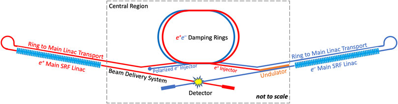
FIGURE 1. Layout of a “generic” SRF linear collider.
As one can see, a high beam power and very small spot sizes at the collision point are required to obtain high luminosity. Thus, achieving a high efficiency of transferring RF to beam power and wall-plug to RF power is very important to colliders. The overall site wall-plug power is usually limited to a few hundreds of megawatts, while the wall-plug to beam power efficiency for linear colliders is of the order of 10%. This constraint necessitates running of linear colliders in a pulsed mode.
On the other hand, it is desirable to reach the collision energy with a linac of a reasonable length. Hence, the RF structures must provide as high rate of acceleration as possible while still maintaining reliable operation. The pulsed mode of operation is beneficial for reaching this goal.
Two types of linear electron–positron colliders under consideration are based on either superconducting or normal-conducting RF accelerating structures. Both have a long history of technology development: a superconducting RF (SRF) linear collider was first proposed in 1965 by Tigner [6]; colliders based on normal-conducting RF accelerating structures are under discussion since the 1970s [7]. The only linear collider realized so far was the Stanford Linear Collider (SLC) at SLAC [8], based on a normal-conducting S-band linac. Among the potential next-generation SRF colliders are the International Linear Collider (ILC) [9], recently proposed HELEN collider [10], and two concepts based on energy recovery linacs: ERLC [11] and ReLiC [12]. The normal-conducting RF linacs are utilized in the Compact Linear Collider (CLIC) [13] and Cool Copper Collider (C3) [14] proposals. In this section, state of the art for the two linear collider technology options and ongoing R&D are considered.
2.1 Superconducting Radio Frequency Linear Colliders
Development of the SRF technology for a linear collider had begun in the 1980’s with a world-wide effort which focused on the TESLA collider proposal [15]. By early 2000’s, the TESLA technology was well-developed already [5, 16], and the SRF option was eventually selected for the ILC. However, the SRF technology continued to make advances to improve the cavity performance, and new e+e− linear collider proposals (including ILC upgrades) have been put forward recently that would utilize the most recent achievements in the SRF technology.
2.1.1 Baseline Superconducting Radio Frequency Technology for the International Linear Collider
The ILC has been the prime candidate for the next e+e− collider, especially since the discovery of the Higgs boson in 2012. The machine was baselined in 2013 [17, 18] and is under consideration to be hosted by Japan [9]. At the first stage, the machine is proposed to operate as a Higgs factory with a center-of-mass energy of 250 GeV. Each of the two Main Linacs accelerate beams from 5 to 125 GeV. The linacs are based on the TESLA technology: 1.3 GHz nine-cell SRF cavities made of bulk niobium (Figure 2), operating at 2 K with an intrinsic cavity quality factor of 1·1010 and providing accelerating gradients of 31.5 MV/m. Because the power dissipation in the cavity walls is extremely small, the accelerating field can be produced with long, ∼0.7 ms, low peak power RF pulses, and a high RF-to-beam-power transfer efficiency, even considering the need to operate at 2 K.

FIGURE 2. 1.3 GHz nine-cell SRF TESLA cavity made of bulk niobium. Courtesy of linearcollider.org.
The TESLA cavities are enclosed in helium vessels, which are filled with 2 K superfluid liquid helium during operation and equipped with fundamental RF power couplers, frequency tuning mechanisms, magnetic shield, and other peripherals. These “dressed” cavities are then assembled into cryomodules comprising either nine cavities or (every third module) eight cavities plus a quadrupole/corrector/beam position monitor unit and all necessary cryogenic supply lines, heat shields, multilayer insulation, etc. Nine cryomodules are powered by two 10-MW L-band multibeam klystrons, thus forming two RF units or one cryostring. RF sources meeting the ILC specifications are commercially available from two vendors, both of which provided klystrons for the European XFEL. The ILC specifications ask for a 65% RF efficiency (drive beam to output RF power). In total, 987 cryomodules will be installed for operation at 250 GeV.
The baseline ILC SRF technology is well-established and was used to build several SRF linacs, with free electron lasers (FELs) European XFEL at DESY, Hamburg, Germany [19], and LCLS-II at SLAC in the United States [20] being the biggest ones. More SRF linacs utilizing this technology are on the horizon, for example, LCLS-II-HE—the high-energy upgrade of LCLS-II at SLAC—and SHINE FEL in China. The European XFEL linac is the largest application of the ILC SRF technology to date. The performance of European XFEL cavities is close to the requirements of the ILC Technical Design Report [17, 18]. For example, 420 cavities from one vendor, which followed the ILC cavity treatment recipe, reached an average gradient of 33.0 ± 6.5 MV/m. More than 10% of cavities from this vendor exceeded 40 MV/m. It is extremely rare that demonstration of a core technology for a future machine exists at such a large scale. Furthermore, ILC-related R&D efforts produced additional proofs of technology readiness. The studies of the cavity performance yield resulted in a (94 ± 6)% yield for cavities with accelerating gradients greater than 28 MV/m and (75 ± 11)% for 35 MV/m. The ensemble of cavities had an average gradient of 37.1 MV/m. Two cryomodules, one at FNAL [21] and one at KEK [22], were tested with beams reaching and even exceeding the ILC specifications. Thus, the baseline ILC SRF technology has been demonstrated and industrialized on a mid-scale and is ready to be deployed.
2.1.2 Superconducting Radio Frequency Advances for International Linear Collider Upgrades, HELEN Collider, and Other Applications
Since the development of baseline ILC technology, the SRF field has continued to make progress in several areas. The key directions for SRF cavity R&D to support future needs of high-energy physics are outlined in the recently published article [23]. Some of the recent advances and results expected in the near future can be applied to the ILC luminosity and energy upgrades [9, 24, 25] or to the recently proposed HELEN collider [10]. Some of the developments discussed below are relevant to other future colliders that utilize SRF technology.
It is important to note that the improvements in gradients should be accompanied by improvements in cavity quality factors to avoid excessively high cavity wall losses and associated thermal effects. This follows from the expression for RF power dissipation in the cavity walls
where
Superconducting properties of niobium—including its surface resistance and breakdown magnetic field—are determined by the state of material within first few tens of nanometers of the surface subjected to the RF field, as the magnetic field penetration depth for clean niobium is about 40 nm. Studies demonstrate that depending on the surface treatment applied to SRF cavities, their surface resistance (and hence quality factor) can vary by almost an order of magnitude. The surface treatment also affects the maximum accelerating gradient that the cavities can operate at.
There was a rapid progress in developing advanced surface treatments over the last decade [23]. Most notably, a nitrogen doping technology allowed reaching unprecedented high-quality factors greater than
In the next sections, a brief review of three possible pathways to achieve higher accelerating gradients in SRF cavities is given.
2.1.2.1 Higher Gradients in Bulk Niobium Standing Wave Accelerating Structures
As mentioned above, over the last decade, a remarkable progress was achieved in improving quality factors and accelerating gradients of bulk niobium cavities. In a recent development, a quench field near 50 MV/m for 1.3 GHz niobium TESLA-shaped SRF single-cell cavities has been achieved with a new 75/120°C two-step bake treatment [29], as shown in Figure 3. The statistics of over 50 cavity tests shows gradients in the range 40–50 MV/m with an average value of 45 MV/m [30].
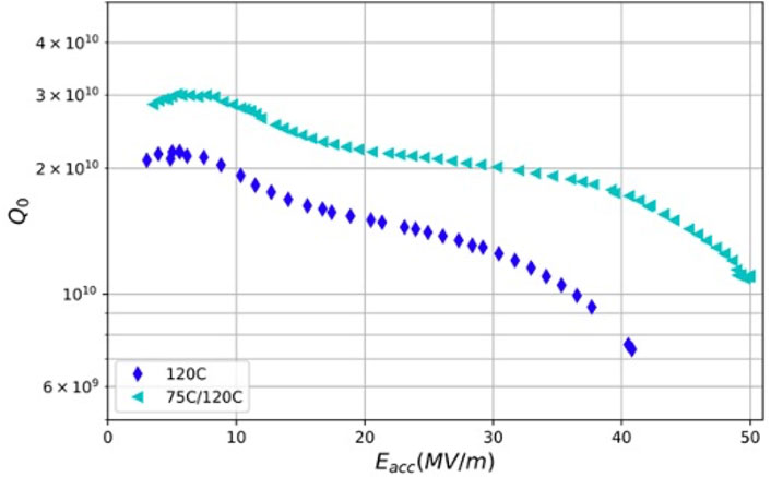
FIGURE 3. Q vs. E curve of single-cell cavity reaching 49 MV/m from cold EP/optimized baking (75/120°C) compared to the curve of a cavity prepared by the standard ILC recipe.
The peak surface magnetic field
Combining the two-step bake with one of the advanced cavity shapes, one can possibly improve the accelerating gradients up to ∼60 MV/m. This combination of advanced cavity treatments and cavity shapes still must be tried and demonstrated, but if successful, it will provide a relatively straightforward path to operating SRF linear colliders at higher gradients with standing wave structures.
2.1.2.2 Traveling Wave Superconducting Radio Frequency Structures
Traveling wave (TW) structures [32] offer several main advantages compared to standing wave ones: substantially lower peak magnetic field, lower peak electric field, and substantially higher
A TW structure provides high stability of the field distribution along the structure with respect to geometrical perturbations. This allows for much longer accelerating structures than TESLA cavities. However, as we can see in Figure 4, an example TW structure with a phase advance of 105 degrees requires almost twice the number of cells per meter—as compared to the TESLA structure—and needs a feedback waveguide for redirecting power from the end to the front of the accelerating structure. The feedback requires careful tuning to compensate reflections along the TW ring and thus obtain a pure traveling wave regime. The challenges of fabricating and surface treatment remain to be addressed to demonstrate feasibility of traveling wave SRF structures, and efforts are underway for a proof-of-principle demonstration [35]. The potential payback of developing full-scale traveling wave SRF cavities is big. It would pave the way for the HELEN collider and/or ILC upgrades to center-of-mass energies beyond 1 TeV.
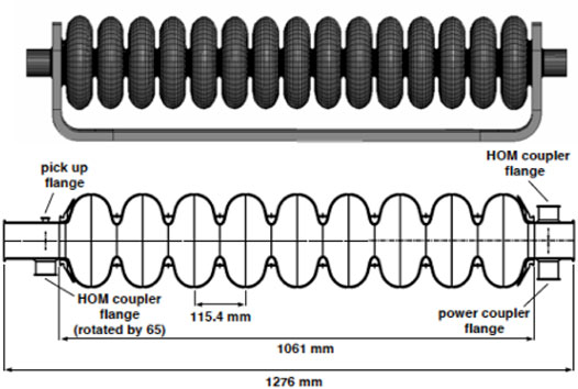
FIGURE 4. Traveling wave structure with a 105° phase advance per cell (top) [34] compared to the one-meter standing wave TESLA structure [16].
2.1.2.3 Advanced Superconducting Radio Frequency Materials
All significant SRF cavity performance results for linear colliders have been achieved with structures made of bulk niobium. There are two main reasons: 1) Nb has the highest critical temperature and critical magnetic field of all elemental superconductors, and 2) it is a ductile metal that can easily be formed into complex geometries of SRF cavities. With niobium cavity gradients approaching the fundamental limit (determined by the Nb superheating magnetic field
In cavity studies, Nb3Sn has a critical temperature of ∼18 K, twice that of Nb, and has already shown high
2.1.3 Other Superconducting Radio Frequency Linear Collider Concepts
Two SRF linear collider proposals based on the energy recovery linac (ERL) concept were published recently: ERLC [11] and ReLiC [12]. While both are still early concepts and require more detailed studies, their main challenges for RF technologies are briefly discussed. The main advantage of using an ERL is that most of the beam energy is recovered after interactions in the detector and re-used for acceleration of the fresh beam. As ERLs operate in either continuous wave (CW) or high-duty factor mode, they promise to deliver much higher luminosities. However, the ERL-based machines face significant challenges that must be addressed when the concepts are developed further. Here, a few of them are listed. First, to keep the cryogenic losses at a reasonable level during CW operation, the accelerating gradients in these two machines are chosen at ∼20 MV/m, which makes the SRF linac significantly longer than the ILC baseline at 31.5 MV/m. Second, the CW beam will produce large higher-order mode (HOM) power. This must be dealt with using beam line HOM absorbers [2], which will further lengthen the linacs. Third, both concepts would need much more expensive SRF cavities compared to the ILC. The ERLC will utilize either twin 1.3 GHz SRF cavities in a single linac or two parallel linacs connected by RF couplers. In either case, the number of cavities increases twofold. ReLiC plans to use five-cell 500 MHz cavities with strong HOM damping, which are much larger than the nine-cell 1.3 GHz TESLA cavities of ILC. These and other challenges make the ERL-based concepts more expensive and power-hungry than ILC, HELEN, or normal conducting linear colliders CLIC and C3. Nevertheless, due to their potential higher luminosities, these two concepts need further detailed scientific and technical validations to address the challenges.
2.2 Normal Conducting Linear Colliders
Two normal conducting linear colliders are being actively developed at present: Compact Linear Collider (CLIC) [13] and Cool Copper Collider (C3) [14]. To limit average power dissipation in the cavity walls at high accelerating gradients, normal conducting structures must operate in the pulsed mode with very short pulses. In addition, the RF power loss per unit length in normal conducting cavities scales as
2.2.1 Radio Frequency for the Compact Linear Collider
The CLIC [13] has been optimized for three center-of-mass energies: 380 GeV, 1.5 TeV, and 3 TeV. It utilizes a novel two-beam acceleration technique. The main linacs accelerate particles from 9 GeV to the collision energy in normal-conducting X-band accelerating structures operating in the range of 70–100 MV/m. The RF power for each main linac is provided by a high-current, low-energy drive beam that runs parallel to the colliding beam through a sequence of power extraction and transfer structures (PETS). The drive beam generates RF power in the PETS that is then transferred to the accelerating structures using a waveguide network. The drive beam is generated centrally with a fundamental frequency of 1 GHz. This concept significantly reduces the cost and power consumption compared with powering the structures directly by klystrons.
CLIC uses 12 GHz traveling wave accelerating structures with a tapered inner aperture diameter ranging from 8.2 to 5.2 mm and are approximately 25 cm in length. The copper structures are assembled from disks machined with micron precision that are joined together using diffusion bonding. HOM suppression is provided by a combination of heavy damping via four terminated waveguides connected to each cell and detuning accomplished through the iris aperture tapering. Figure 5 illustrates the micron-precision disk (the basic assembly block of the CLIC structure) and an assembly drawing of the acceleration unit.
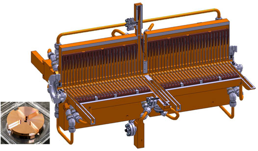
FIGURE 5. Left: The basic assembly block of the CLIC structure with four waveguides providing HOM damping. Right: Assembly drawing of the double-structure acceleration unit (Image credit: CLIC) [13].
For the collision energy of 380 GeV, the main linac structures accelerate a train of bunches with a gradient of 72 MV/m and must maintain a breakdown rate of less than 3·10–7 m−1. The pulse length is 233 ns, and the repetition rate is 50 Hz. The linacs operate at very high beam loading to enable high beam current and high RF-to-beam efficiency. The performance aspects of the structures have been validated in a series of dedicated tests. The tests included an experiment at CTF3 at CERN to determine the effect of heavy beam loading. Fully assembled two-beam modules have been tested with and without the beam. All elements for the waveguide system have been designed, fabricated, and operated to full specifications. All these efforts demonstrated that the CLIC RF design parameters are well-understood and can be reliably reproduced in tests. Further studies will put an emphasis on optimizing cost and energy efficiency of the RF system.
2.2.2 Optimized C-Band RF Structures for C3
C3 [14] is an e+e− linear collider based on a novel approach to normal conducting linacs that achieves both high gradient and high efficiency. C3 would be a Higgs factory operating at 250 GeV with a straightforward upgrade path to 550 GeV, while staying on the same short facility footprint.
There are several distinct features that set the C3 accelerating structures apart from traditional electron linacs. First, the cavity cells are optimized for high shunt impedance and low surface electric and magnetic fields. This necessarily led to a spherical reentrant geometry with “nose cones” that is typical, for example, for single-cell cavities of synchrotrons and storage rings [41]. However, such cells have beam apertures that are too small for sufficient cell-to-cell coupling of the fundamental RF mode, thus precluding on-axis coupling of RF power to the structure. Second, to circumvent this, a distributed coupling scheme (previously used at other laboratories in different configurations, see for example, [42, 43]) via parallel manifold RF waveguides provides side-coupling into each cell with the proper RF phase. Figure 6 shows a 3D model of the proposed C-band (5.712 GHz) structure and magnitude of electric and magnetic field in the accelerating cell. While this structure is relatively complex, it was demonstrated that it could be machined in two halves (or four quarters) by a CNC milling machine [44]. This fabrication process provides ultra-high-vacuum (UHV) quality surfaces that need no further finishing apart from a standard copper surface etch. Finally, the copper structures will operate in a liquid nitrogen bath at a cryogenic temperature of about 80 K. The advantage is two-fold: the increase of electrical conductivity and improvement of the material strength. The increased electrical conductivity results in reduction of RF losses in the cavity walls and the required RF power. The lower thermal stresses in the material and improved material strength reduce the probability of breakdown. Theoretical predictions of the copper surface resistance, confirmed by the experiment [45], show that almost all the improvement (factor of 2.55 compared to 300 K for RRR = 400 copper at 5.712 GHz) is achieved by cooling the material down to liquid nitrogen temperature.
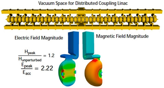
FIGURE 6. Top: C3 accelerating structure. Bottom: 3D model of a 1-m-long 40-cell C-band accelerating structure operating in the π mode. The magnitude of the electric and magnetic field in each cell. The peak surface electric field to accelerating gradient ratio is 2.22. The perturbation to the magnetic field from the RF coupler increases the peak magnetic field by 1.2 [14].
The main linac will consist of one-meter-long structures operating at an accelerating gradient of 70 MV/m with pulse length of 700 ns and repetition rate of 120 Hz. For 550 GeV upgrade, the gradient will be raised to 120 MV/m with a shorter, 250 ns, pulse length. Prototype one-meter structures have been fabricated and tested at high gradient and at cryogenic temperatures. The next step is to develop an HOM damped and detuned design to mitigate the effect of the long-range wakefields. This will be accomplished differently from the CLIC design. Detuning of HOMs will be achieved by modifying the geometry of each cavity, while maintaining constant frequency of the fundamental mode. For damping, longitudinal damping slots in quadrature will be added to the structure design. While for the Higgs factory operation, C3 can use commercially available 50 MW C-band klystrons and modulators, it is highly desirable to develop RF sources with better efficiency and higher power (especially for the energy upgrade).
3 Future Circular Colliders
First lepton circular colliders began operating in mid-1960s, see overview of collider development in [1]. Since that time, all colliders except the SLC at SLAC have been of this type. The energy and luminosity of every new generation of the particle colliders grew steadily in tandem with advances in key accelerator technologies and beam physics techniques. All contemporary colliders consist of two rings storing counter-rotating beams that intersect at one or more interaction points. The two rings may store particles of the same type or particles and their anti-particles or particles of two different types. The collisions may be symmetric (two beams having the same energy) or asymmetric. The current frontier colliders are the 13-TeV Large Hadron Collider (LHC) at CERN and asymmetric 4 by 7 GeV e+e− Super B factory (Super-KEKB) at KEK in Japan.
Several new colliders are under consideration to be built in the next couple of decades. For hadrons, the luminosity of the LHC will be upgraded first to the HL-LHC to improve the discovery reach of the machine at center-of-mass energies up to 14 TeV. The next-generation energy frontier hadron machines would be ∼100-km circumference colliders FCC-hh [46] at CERN and SppC [47] in China, both of which have a target energy of ∼100 TeV. However, to reach their design energies, these colliders need to develop superconducting magnet technology beyond state of the art that would take some time. Thus, before building hadron colliders, both teams consider building symmetric circular e+e− colliders in the same tunnels first. These are called FCC-ee [48] and CEPC [49], respectively. They will be able to run in a range of center-of-mass energies from 91 GeV (Z-pole) to ∼360 GeV (
where
Now, for flat beams (
where
The synchrotron radiation power must be compensated by the collider’s RF system. Thus, achieving a high efficiency of transferring RF power to beam and wall-plug to RF power is very important to colliders, resembling the case of linear colliders.
In addition to FCC-ee and CEPC, an ERL-based e+e− collider CERC was proposed recently [51]. Finally, there is an interest in electron-hadron colliders. In particular, an electron-ion collider EIC is being designed at BNL in the United States [52]. EIC will be built in the existing RHIC tunnel by adding three new rings, strong hadron cooling, and upgrading the injector complex.
All circular colliders will need advanced radio frequency systems that must be able to deliver high CW RF power to ampere-class beams via strongly HOM-damped SRF cavities. In this section, the designs and challenges of several such cavities are reviewed.
3.1 Higher-Order Mode Damped Superconducting Radio Frequency Cavities for Circular Colliders
The first strongly HOM damped SRF cavities [53] were developed in the early 1990s for e+e− colliders CESR at Cornell in the United States and KEKB in Japan. These single-cell cavities are made of bulk niobium and operate at 500 and 509 MHz, respectively. Both cavities have very large beam pipes allowing HOMs to propagate toward water-cooled ferrite absorbers located outside the cryomodules. The 400-MHz LHC cavities use niobium-film-on-copper (Nb/Cu) technology, developed originally for LEP2 cavities. HOM damping is achieved with two types of coaxial HOM couplers attached to the large beam tubes. The first type is a narrow-band coupler (one per cavity) which damps the first two dipole modes, while two couplers of the second type are broad-band to damp all other HOMs [54]. These three HOM damped cavities have been state of the art for colliders and storage ring-based light sources since their development and implementation. The next-generation particle colliders require updated, custom designs.
CEPC will use two-cell 650 MHz cavities. Two coaxial HOM couplers with double-notch filters are installed on both sides of the cavity, as shown in Figure 7, with orientation optimized for best damping [55]. 240 such cavities will be installed for the Higgs operation. For the
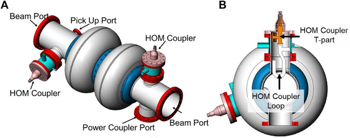
FIGURE 7. CEPC cavity model with HOM couplers (A) and a cross-sectional view at the fundamental power port (B) [55].
The conceptual design of FCC-ee envisages using cavities at two frequencies. Fifty-two single-cell, LHC-like, 400 MHz Nb/Cu cavities will be used at the Z-pole energy. At the WW threshold and ZH modes of operation, four-cell 400 MHz Nb/Cu cavities (52 and 136, respectively) will replace the single-cell cavities. Five-cell 800 MHz cavities made of bulk niobium will be added to boost the required RF voltage to 11.25 GV at the highest energy, where HOM damping requirements are relaxed, and smaller cavities would provide better efficiency and cost savings. The 400 MHz cavities would operate at 4.5 K and the 800 MHz cavities—at 2 K. A new design concept of a two-cell 600 MHz superconducting Slotted Waveguide Elliptical cavity (SWELL) was recently proposed as a potential option for FCC-ee [56]. The design (Figure 8) borrows the idea from normal conducting structures where a similar approach was realized, for example, in Slotted Irises Constant Aperture (SICA) 3 GHz accelerating structure used in CTF3 [57]. It is proposed that the SWELL cavity quadrant would be machined from copper and then coated with a thin film of niobium. While computer simulations show good HOM damping, the design looks quite exotic for a superconducting cavity. There are still many technological challenges to be addressed—fabrication tolerances, niobium coating, clean assembly, tuning, etc.—before one can discuss practicality of this proposal.
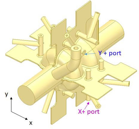
FIGURE 8. 3D model showing two coaxial HOM ports located on the orthogonal branches of the SWELL cavity [56].
Several new SRF and normal conducting cavities of different types will be installed in the new EIC accelerators at BNL [52]. Consider, for example, the electron storage ring, which will operate in a beam energy range from 2.5 to 18 GeV, with beam current up to 2.5 A. Seventeen single-cell 591 MHz SRF cavities will have to deal with compensating 9 MW of beam power loss to synchrotron radiation and 1 MW of HOM losses. Each cavity has dual 400-kW fundamental power couplers. Strong HOM damping is provided by broad-band SiC HOM absorbers located outside cryomodules as shown in Figure 9.
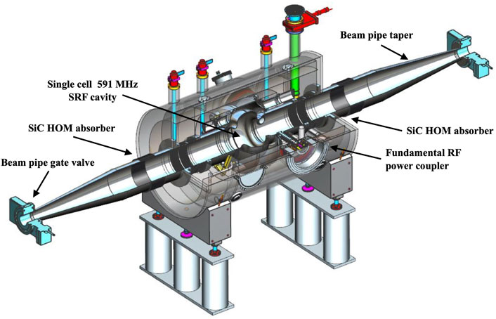
FIGURE 9. Cut-out view of the EIC electron storage ring SRF cryomodule concept (adapted from [52]).
4 Common Radio Frequency Technologies
There are RF technology areas that are common to linear and circular colliders. Here, two such areas: crab cavities and high-efficiency, low-cost klystrons are considered.
4.1 Crab Cavities
In future machines, the colliding beam trajectories will intersect at interaction points (IPs) at a small crossing angle. This is carried out to mitigate parasitic collisions, simplify removing of spent beams, etc. Such an intersection reduces the geometric overlap of the beams and the peak luminosity, as a result. In some cases, for example, with a relatively large crossing angle or with mismatch of the bunch lengths, the effect can be large. Using a crab crossing scheme, proposed by Palmer in 1988 [4], allows reestablishing full bunch overlapping during collision.
A deflecting (crab) cavity operates in such a way that the bunch center gets a zero kick, while its head and tail receive opposite transverse kicks with equal magnitude. The bunch is “chirped” and it moves along the trajectory in a crab-like manner. After the IP, another crab cavity can be installed to un-crab the bunch. Figure 10 illustrates the crab crossing concept.
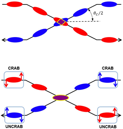
FIGURE 10. Sketch illustrating crab crossing concept. Top: Beam collision scheme with crossing angle. Bottom: Crab crossing restores full bunch overlapping (Adapted from [58]).
The crab crossing scheme was first implemented at the KEK B factory. The KEKB crab cavities were single-cell elliptical SRF structures operating at 4.5 K. The TM110-like mode with a resonant frequency of 509 MHz was used for crabbing the beams. The cavity had a special coaxial coupler to damp the fundamental mode and large beam pipes for suppressing HOMs. The cell had a squashed shape to split two deflecting modes and select one polarization [59]. The cavities successfully crabbed the KEKB bunches to provide head-on collisions in the detector. To date, this has been the only operational collider with the crab crossing collision scheme.
HL-LHC will increase the LHC luminosity via several upgrades of the machine. As part of these upgrades, a crab crossing scheme will be implemented. The HL-LHC SRF crab cavities will operate at 400 MHz. As the real estate available for crab cavities in the collider is very tight, design studies were initiated to develop very compact deflecting cavities that would fit into the available space. Two novel compact designs were selected: RF Dipole (RFD) and Double Quarter Wave (DQW) resonators. For more details, see [58, 60] and the references therein.
ILC is currently following a similar path, going through a design study of various crab cavity proposals, including multi-cell elliptical cavity, RFD, DQW, and other design options with operating frequencies from 1.3 to 3.9 GHz.
Due to different bunch lengths of hadron and electron beams in the EIC, the crab crossing scheme will utilize cavities at two frequencies, 197 and 394 MHz. The hadron storage ring will use eight and four cavities at these two frequencies, respectively, while the electron ring will need only two cavities at 394 MHz [52]. The design studies are underway with the two main options being RFD and DQW. EIC imposes more stringent requirements on the HOM impedance of crab cavities than HL-LHC. As a result, the HL-LHC crab cavity HOM dampers cannot be adopted to EIC directly. The design updates are in progress. Figure 11 illustrates the design of the baseline 197 MHz RFD crab cavity with two waveguide HOM couplers.
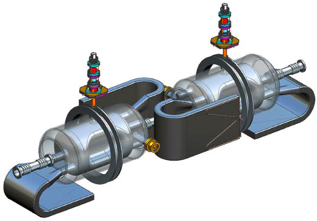
FIGURE 11. 3D model of the RFD cavity concept showing two cavities with HOM waveguides [52].
4.2 High-Efficiency, Low-Cost Klystrons
As it was mentioned already, achieving high efficiency is very important, especially for the RF systems of future colliders. Here, several recent developments in this area are mentioned. The High-Efficiency International Klystron Activity (HEIKA) collaboration [61, 62] investigates novel techniques for high-efficiency klystrons. Techniques such as the Bunching, Alignment, and Collecting (BAC) method [63] and the Core Oscillation Method (COM) [64] have been developed that promise increased efficiencies up to 90% [65]. One advantage of these methods is that it is possible to increase the efficiency of existing klystrons by equipping them with a new electron optics, as was demonstrated retrofitting an existing tube: the output power was increased by almost 50% and the klystron efficiency from 42% to 66% [66]. Incorporating periodic permanent magnet focusing can further reduce fabrication and operation costs. Another approach is to develop a simple modular system that would combine power of several low-voltage, highly efficient klystrons [44, 67].
5 Radio Frequency Technology Challenges of Muon Collider
The muon collider can potentially extend the energy reach of lepton colliders to much higher energies, up to a 10 TeV center of mass [68]. Thus, such a machine can serve for both precision and discovery studies. It is expected that the collider’s overall power consumption will be lower than that of the CLIC at 3 TeV. The machine would be relatively compact and could accommodate two experiments. While past efforts have demonstrated several key technologies, more R&D is needed before a fully integrated design could be developed. RF is one of the key technologies for the muon collider that must be part of a future R&D program.
Both normal conducting and superconducting RF will be utilized in different accelerators of the muon collider complex. A muon ionization cooling employs normal conducting 325 and 650 MHz RF cavities capable of providing high accelerating gradients in the presence of multi-tesla DC solenoid magnetic fields. Following that, a beam acceleration system includes SRF cavities operating at frequencies of 325, 650, and 1,300 MHz. These cavities must be robust to beam loading and capable of delivering significant gradients for rapid muon acceleration. No such cavities have been developed yet.
To yield good cooling performance in the cooling system, a compact lattice with large real-estate RF gradient is required. This results in RF cavities operating near to the breakdown limit while immersed in a strong solenoid field and poses specific challenges. The solenoid field guides electrons that are emitted at one location of the cavity surface to another location on the opposing wall and leads to localized heating that can result in breakdown and cavity damage. Operation of copper cavities in a 3 T magnetic field showed a maximum useable gradient of only 10 MV/m. It was proposed to use lower-Z materials such as beryllium to limit the energy loss density. Experiments with an 805 MHz beryllium cavity under vacuum yielded a gradient of 50 MV/m in an external magnetic field of 3 T [69]. Further efforts are needed to study alternative materials, for example, aluminum and fully develop the cavities at required frequencies.
6 Summary
Radio frequency technologies will continue to be critical to the success of future colliders regardless of the collider configuration or particles being collided. In this article, we have tried to give the readers a broad, high-level overview of the field, highlighting recent advances, new ideas to pursue, and challenges that future colliders need to address. While most of the article was focused on accelerating structures, a couple of other technologies were mentioned: crab cavities and high-efficiency, high-power klystrons. Performance of the RF systems strongly influences the luminosity and energy reach of the colliders either directly or indirectly via the capital and operational costs. Advances in RF technologies will continue to enable new proposals, such as the recently put forward linear colliders C3 and HELEN.
Author Contributions
The author confirms being the sole contributor of this work and has approved it for publication.
Funding
Work supported by the Fermi National Accelerator Laboratory, managed and operated by Fermi Research Alliance, LLC under Contract No. DE-AC02-07CH11359 with the US Department of Energy. The US Government retains and the publisher, by accepting the article for publication, acknowledges that the US Government retains a non-exclusive, paid-up, irrevocable, world-wide license to publish or reproduce the published form of this manuscript, or allow others to do so, for US Government purposes.
Conflict of Interest
The author declares that the research was conducted in the absence of any commercial or financial relationships that could be construed as a potential conflict of interest.
Publisher’s Note
All claims expressed in this article are solely those of the authors and do not necessarily represent those of their affiliated organizations, or those of the publisher, the editors, and the reviewers. Any product that may be evaluated in this article, or claim that may be made by its manufacturer, is not guaranteed or endorsed by the publisher.
References
1. Shiltsev V, Zimmermann F. Modern and Future Colliders. Rev Mod Phys (2021) 93(61):015006. doi:10.1103/revmodphys.93.015006
2. Belomestnykh S. Superconducting Radio-Frequency Systems for High-β Particle Accelerators. Rev Accel Sci Tech (2012) 05:147–84. doi:10.1142/s179362681230006x
3. Nassiri A, Chase B, Craievich P, Fabris A, Frischholz H, Jacob J, et al. History and Technology Developments of Radio Frequency (RF) Systems for Particle Accelerators. IEEE Trans Nucl Sci (2016) 63:707–50. doi:10.1109/tns.2015.2485164
4. Palmer R. B. Energy Scaling, Cab Crossing and the Pair Problem. C8806271:613-619. SLAC-PUB-4707 (1988).
5.TESLA Technical Design Report. Part II: The Accelerator. R Brinkmann, K Flöttmann, J Roßbach, P Schmüser, N Walker, and H Weise, editors (2001). Available from: https://flash.desy.de/sites2009/site_vuvfel/content/e1549/e1506/e1509/infoboxContent1511/partII.pdf (Accessed May 26, 2022).
6. Tigner M. A Possible Apparatus for Electron Clashing-Beam Experiments. Nuovo Cim (1965) 37:1228–31. doi:10.1007/bf02773204
7. Balakin VE, Skinsky AN. A Superhigh Energy Colliding Electron-Positron Beam Facility (VLEPP). In: Proc. 2nd ICFA Workshop on Possibilities and Limitations of Accelerators and Detectors (1979). p. 31.
9.The ILC International Development Team and the ILC Community: Report to Snowmass 2021. arXiv:2203.07622 [physics.acc-ph] (2022).
10. Belomestnykh S, Bhat PC, Grassellion A, Checchin M, Denisov D, Geng RL, et al. Higgs-Energy LEptoN (HELEN) Collider Based on Advanced Superconducting Radio Frequency Technology. arXiv:2203.08211 [physics.acc-ph] (2022).
11. Telnov VI. A High-Luminosity Superconducting Twin e+e- Linear Collider with Energy Recovery. J Inst (2021) 16:P12025. doi:10.1088/1748-0221/16/12/p12025
12. Litvinenko VN, Bachhawat N, Chamizo-Llatas M, Jing Y, Méot F, Petrushina I, et al. The ReLiC: Recycling Linear e+e– collider. arXiv:2203.06476 [hep-ex] (2022).
13. Brunner O, Burrows PN, Calatroni S, Catalan Lasheras N, Corsini R, D’Auria G, et al. The CLIC Project. arXiv:2203.09186 [physics.acc-ph] (2022).
14. Bai M, Barklow T, Bartoldus R, Breidenbach M, Grenier P, Huang Z, et al. C3: A “Cool” Route to the Higgs Boson and Beyond. arXiv:2110.15800 [hep-ex] (2021).
15.The First TESLA Collider Workshop. Cornell Report CLNS 90-1029. Ithaca, NY: Cornell University (1990).
16. Aune B, Bandelmann R, Bloess D, Bonin B, Bosotti A, Champion M, et al. Superconducting TESLA Cavities. Phys Rev Accel Beams (2000) 3:092001. doi:10.1103/PhysRevSTAB.3.092001
17. Adolphsen C, Barone M, Barish B, Buesser K, Burrows P, Carwardine J, et al. The International Linear Collider Technical Design Report – Volume 3.I: Accelerator R&D in the Technical Design Phase. arXiv:1306.6353 [physics.acc-ph] (2013).
18. Adolphsen C, Barone M, Barish B, Buesser K, Burrows P, Carwardine J, et al. The International Linear Collider Technical Design Report – Volume 3.II: Accelerator Baseline Design. arXiv:1306.6328 [physics.acc-ph] (2013).
19.The European X-Ray Free-Electron Laser: Technical Design Report. (2007). Available from: https://bib-pubdb1.desy.de/record/77248/files/european-xfel-tdr.pdf. (Accessed May 26, 2022).
20. Raubenheimer TO for the LCLS-II Collaboration. Technical Challenges of the LCLS-II CW X-Ray FEL. In: Proc. 6th Int. Particle Accel. Conf. IPAC2015. Richmond, VA, USA (2015). p. 2434–8.
21. Broemmelsiek D, Chase B, Edstrom D, Harms E, Leibfritz J, Nagaitsev S, et al. Record High-Gradient SRF Beam Acceleration at Fermilab. New J Phys (2018) 20:113018. doi:10.1088/1367-2630/aaec57
22. Yamamoto Y, Kako E, Umemori K, Sakai H, Saeki T, Dohmae T, et al. Stable Beam Operation at 33 MV/m in STF-2 Cryomodules at KEK. In: Proc. SRF2021. East Lansing, MI, USA (2021).
23. Belomestnykh S, Posen S, Bafia D, Balachandran S, Bertucci M, Burrill A, et al. Key Directions for Research and Development of Superconducting Radio Frequency Cavities. arXiv:2204.01178 [physics.acc-ph] (2022).
24. Padamsee H, Grassellino A, Belomestnykh S, Posen S. Impact of High Q on ILC250 Upgrade for Record Luminosities and Path Toward ILC380. arXiv:1910.01276 [physics.acc-ph] (2019).
26. Gonnella D for the LCLS-II-HE Collaboration. LCLS-II-HE High Q0 & Gradient R&D Program, First CM Test Results, and CM Plasma Processing Results. In: Presentation at the Virtual TESLA Technology Collaboration Meeting (2022).
27. Martinello M, Bice DJ, Boffo C, Chandrasekeran SK, Eremeev GV, Furuta F, et al. Q-Factor Optimization for High-Beta 650 MHz Cavities for PIP-II. J Appl Phys (2021) 130:174501. doi:10.1063/5.0068531
28. Posen S, Romanenko A, Grassellino A, Melnychuk OS, Sergatskov DA, et al. Ultralow Surface Resistance via Vacuum Heat Treatment of Superconducting Radio-Frequency Cavities. Phys. Rev. Appl. (2020) 13:014024. doi:10.1103/PhysRevApplied.13.014024
29. Grassellino A, Romanenko A, Bice D, Melnychuk O, Crawford AC, Chandrasekaran S, et al. Accelerating Fields Up to 49 MV/m in TESLA-Shape Superconducting RF Niobium Cavities via 75C Vacuum Bake. arXiv:1806.09824 [physics.acc-ph] (2018).
30. Bafia D, Grassellino A, Sung Z, Romanenko A, Melnychuk OS, Zasadzinski JF. Gradients of 50 MV/m in TESLA Shaped Cavities via Modified Low Temperature Bake. In: Proc. 19th Int. Conf. on RF Superconductivity SRF2019. Dresden, Germany (2019). p. 586–91.
31. Padamsee H. New Cavity Geometries. In: RF Superconductivity: Science, Technology, and Applications. WILEY-VCH Verlag GmbH & Co. KGaA (2009). p. 10–8.
32. Avrakhov P, Kanareykin A, Solyak N. Traveling Wave Accelerating Structure for a Superconducting Accelerator. Knoxville, TN, USA: Proc. PAC2005 (2005). p. 4296–8.
33. Shemelin V, Padamsee H, Yakovlev V. Optimization of a Traveling Wavesuperconducting Rf Cavity for Upgrading the International Linear Collider. Phys Rev Accel Beams (2022) 25:021001. doi:10.1103/physrevaccelbeams.25.021001
34. Yakovlev V, Avrakhov P, Kanareykin A, Kazakov S, Solyak N. Progress Towards Development of a Superconducting Traveling Wave Accelerating Structure. Albuquerque, NM, USA: Proc. PAC2007 (2007), p. 2182-4.
35. Kostin R, Avrakhov P, Kanareykin A, Yakovlev V, Solyak N. Progress Towards 3-Cell Superconducting Traveling Wave Cavity Cryogenic Test. J Phys Conf Ser (2017) 941:012100. doi:10.1088/1742-6596/941/1/012100
36. Valente-Feliciano A-M, Antoine C, Anlage S, Ciovati G, Delayen J, Gerigk F, et al. Next-Generation Superconducting RF Technology Based on Advanced Thin Film Technologies and Innovative Materials for Accelerator Enhanced Performance & Energy Reach. arXiv:2204.02536 [physics.acc-ph] (2022).
37. Valente-Feliciano A-M. Superconducting RF Materials Other Than Bulk Niobium: A Review. Supercond Sci Technol (2016) 29:113002. doi:10.1088/0953-2048/29/11/113002
38. Posen S, Liepe M, Eremeev G, Pudasaini U, Reece CE. Nb3Sn Superconducting Radiofrequency Cavities: A Maturing Technology for Particle Accelerators and Detectors. arXiv:2203.06572 [physics.acc-ph] (2022).
39. Posen S, Lee J, Seidman DN, Romanenko A, Tennis B, Melnychuk OS, et al. Advances in Nb3Sn Superconducting Radiofrequency Cavities Towards First Practical Accelerator Applications. Supercond Sci Technol (2021) 34:025007. doi:10.1088/1361-6668/abc7f7
40. Dhuley RC, Gonin I, Kazakov S, Khabiboulline T, Sukhanov A, Yakovlev V, et al. Design of a 10 MeV, 1000 kW Average Power Electron-Beam Accelerator for Wastewater Treatment Applications. Phys Rev Accel Beams (2022) 25:041601. doi:10.1103/physrevaccelbeams.25.041601
41. Rimmer R. Single Cell Cavities. In: Handbook of Accelerator Physics and Engineering. 2nd ed. World Scientific (2013). p. 672–4.
42. Sundelin RM, Kirchgessner JL, Tigner M. Parallel Coupled Cavity Structure. IEEE Trans Nucl Sci (1977) 24(3):1686–8. doi:10.1109/tns.1977.4329052
43. Brezhnev ON, Logatchev PV, Pavlov VM, Pirogov OV, Shiyankov SV, Chernousov JD, et al. Parallel-Coupled Accelerating Structures. Gyeongju, Korea: Proc. LINAC2002 (2002). p. 213–5.
44. Nanni EA, Breidenbach M, Vernieri C, Belomestnykh S, Bhat PC, Nagaitsev S, et al. C3 Demonstration Research and Development Plan. arXiv:2203.09076 [physics.acc-ph] (2022).
45. Cahill A, Fukasawa A, Rosenzweig J, Higashi Y, Bowden GB, Dolgashev VA, et al. Measurements of Copper RF Surface Resistance at Cryogenic Temperatures for Applications to X-Band and S-Band Accelerators. Busan, Korea: Proc. IPAC2016 (2016). p. 487–90.
46. Benedikt M, Chance A, Dalena B, Denisov D, Giovannozzi M, Gutleber J, et al. Future Circular Hadron Collider FCC-hh: Overview and Status. arXiv:2203.07804 [physics.acc-ph] (2022).
47. Tang J, Zhang Y, Xu Q, Gao J, Lou X, Wang Y. Study Overview for Super Proton-Proton Collider. arXiv:2203.07987 [hep-ex] (2022).
48. Agapov I, Benedikt M, Blondel A, Boscolo M, Brunner O, Chamizo Llatas M, et al. Future Circular Lepton Collider FCC-Ee: Overview and Status. arXiv:2203.08310 [physics.acc-ph] (2022).
49.CEPC Accelerator Study Group. Snowmass2021 White Paper AF3- CEPC. arXiv:2203.09451 [physics.acc-ph] (2022).
50. Abada A, Abbrescia M, AbdusSalam SS, Abdyukhanov I, Abelleira Fernandez J, Abramov A, et al. FCC-ee: The Lepton Collider. Eur Phys J Spec Top (2019) 228:261–623. doi:10.1140/epjst/e2019-900045-4
51. Litvinenko VN, Bachhawat N, Chamizo-Llatas M, Meot F, Roser T. CERC – Circular e+e- Collider Using Energy-Recovery Linac. arXiv:2203.07358 [physics.acc-ph] (2022).
52.Electron-Ion Collider at Brookhaven National Laborator. Electron Ion Collider Conceptual Design Report (2021). Available from: https://www.bnl.gov/ec/files/eic_cdr_final.pdf (Accessed May 26, 2022).
53. Belomestnykh S, Kirchgessner J. Superconducting Single Cell Cavities. In: Handbook of Accelerator Physics and Engineering. World Scientific (2013). p. 683–7.
55. Zheng H, Sha P, Zhai J, Pan W, Li Z, Mi Z, et al. Development and Vertical Tests of 650 MHz 2-Cell Superconducting Cavities with Higher Order Mode Couplers. Nucl Instrum Methods Phys Res A (2021) 995–165093. doi:10.1016/j.nima.2021.165093
56. Syratchev I, Peauger F, Karpov I, Brunner O. A Superconducting Slotted Waveguide Elliptical Cavity for FCC-Ee. CERN Report FCC-2105010000-OBR (2021).
57. Jensen E. CTF3 Drive Beam Accelerating Structures. Gyeongju, Korea: Proc. LINAC2002 (2002). p. 34–6.
58. Verdú-Andrés S, Belomestnykh S, Ben-Zvi I, Calaga R, Wu Q, Xiao B. Crab Cavities for Colliders: Past, Present and Future. Nucl Part Phys Proc (2016) 273-275:193–7. doi:10.1016/j.nuclphysbps.2015.09.025
59. Abe T, Akai K, Akemoto M, Akiyama A, Arinaga M, Ebihara K, et al. Compensation of the Crossing Angle with Crab Cavities at KEKB. Albuquerque, NM, USA: Proc. PAC2007 (2007). p. 27–31.
60. Verdú-Andrés S, Ben-Zvi I, Wu Q, Calaga R. Crab Cavity Systems for Future Colliders. Copenhagen, Denmark: Proc. IPAC2017 (2017). p. 2474–7.
61. Syratchev I. Introduction to the High Efficiency International Klystron Activity HEIKA. Geneva, Switzerland: Presentation at CLIC Workshop 2015.
62. Gerigk F. Status and Future Strategy for Advanced High Power Microwave Sources for Accelerators. In: Proc. 9th International Particle Accelerator Conference (IPAC 2018). Vancouver, BC: Canada (2018). p. 12–7.
63. Guzilov IA. BAC Method of Increasing the Efficiency in Klystrons. In: Proc. 10th International Vacuum Electron Sources Conference (IVESC) (2014). p. 1–2.
64. Constable D, Baikov A, Burt G, Guzilov I, Hill V, Jensen A, et al. High Efficiency Klystron Development for Particle Accelerators. In: Proc. 58th ICFA Advanced Beam Dynamics Workshop on High Luminosity Circular e+e- Colliders (eeFACT2016). Daresbury, UK (2016). p. 185–7.
65. Baikov AY, Marrelli C, Syratchev I. Toward High-Power Klystrons with RF Power Conversion Efficiency on the Order of 90%. IEEE Trans Electron Dev (2015) 62:3406.
66. Jensen E. Recent Developments Towards Very High Efficiency Klystrons. In: Presentation at 9th CW and High average RF power workshop. Grenoble, France (2016).
67. Weatherford B, Nanni E, Tantawi S. Advanced RF Sources R&D for Economical Future Colliders. In: arXiv:2203.15984 [physics.acc-ph] (2022).
68. Stratakis D, Mokhov N, Palmer M, Pastrone N, Raubenheimer T, Rogers C, et al. A Muon Collider Facility for Physics Discovery. arXiv:2203.08033 [physics.acc-ph] (2022).
Keywords: acceleration, cavity, collider, klystron, linac, radio frequency, storage ring, superconductivity
Citation: Belomestnykh S (2022) RF Technologies for Future Colliders. Front. Phys. 10:933479. doi: 10.3389/fphy.2022.933479
Received: 30 April 2022; Accepted: 27 May 2022;
Published: 09 August 2022.
Edited by:
Patrizia Azzi, National Institute of Nuclear Physics of Padova, ItalyReviewed by:
Serkant Ali Çetin, University of Istinye, TurkeyJie Gao, Institute of High Energy Physics (CAS), China
Akira Yamamoto, High Energy Accelerator Research Organization, Japan
Copyright © 2022 Belomestnykh. This is an open-access article distributed under the terms of the Creative Commons Attribution License (CC BY). The use, distribution or reproduction in other forums is permitted, provided the original author(s) and the copyright owner(s) are credited and that the original publication in this journal is cited, in accordance with accepted academic practice. No use, distribution or reproduction is permitted which does not comply with these terms.
*Correspondence: Sergey Belomestnykh, c2JlbG9tZXNAZm5hbC5nb3Y=