 Jiang Chen
 Ji Wang1,2
- 1Science and Technology on Vacuum Technology and Physics Laboratory, Lanzhou, China
- 2Lanzhou Institute of Physics, Lanzhou, China
This paper introduces a compact magnetic state-selection cesium atomic clock called LIP Cs-3000 and analyses its characteristics. The test results reveal that the ranges of the line width, peak-to-valley ratio and signal-to-noise ratio of Ramsey pattern are 340–410 Hz, 2–13 and 2,000–8,000 respectively. The corresponding distributions of these parameters are derived by using statistical methods. According to these results, some suggestions are put forward for the further development of the clock. It is also pointed out that the most important factor affecting the accuracy of LIP Cs-3000 atomic clock is the uncertainty of cavity phase shift. In addition, the method to estimate the lifetime of a clock has been proposed. In the end, the paper gives some environmental adaptability designs of the clock, which enable the clock to be used in complex environments.
Introduction
The function of a compact cesium atomic clock with magnetic state selection is to realize the definition of SI second in a continuous and reliable manner, providing the user with frequency signals with high stability and accuracy. Thus this kind of clock has been widely used in time keeping, navigation, positioning, communication, and other fields in the world [1–7].
Presently, there are several brands of such atomic clock that can be available on the market. The cesium clock 5071A has specifications with an accuracy of
To solve this problem, the paper introduces a compact magnetic state-selection cesium clock called LIP Cs-3000 which was developed at Lanzhou Institute of Physics in China [10, 11]. The paper adopts statistical methods to obtain the distributions of the line width, signal-to-noise and peak-to-valley ratio of Ramsey pattern. Based on the results, the range of stability of LIP Cs-3000 is calculated and the further development of the clock is suggested. The paper also analyzes various factors affecting accuracy and points out that the most important factor is the uncertainty of cavity phase shift. We expect that this conclusion will help improve the accuracy of the atomic clock in the future. In addition, the paper studies how to estimate the lifetime of LIP Cs-3000 clock and derives that the lifetime of the clock is larger than 5 years. The formula for assessing lifetime can be also used in other brands of cesium atomic clocks. In the end, the paper gives some environmental tests of LIP Cs-3000, which show that the clock can be applied to some complex environments. The contents of this paper not only contribute to the further development of LIP Cs-3000, but also can be applied to other brands of compact cesium atomic clocks to improve performance.
Principle and scheme
LIP Cs-3000 (see Figure 1) uses an identical two-wire magnetic field which realized by Stern-Gerlach magnet to prepare and detect atomic states and Ramsey-separated field excitation to achieve the state transitions [6, 7]. The transition signal is sent to a servo system to tune a voltage controlled crystal oscillator (VCXO).
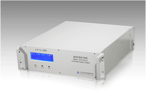
FIGURE 1. LIP Cs-3000 cesium atomic clock. The overall dimension of the LIP Cs-3000 is 435 mm × 133 mm × 500 mm. It is the standard dimension of the 3U case. Thus the LIP Cs-3000 could easily been installed on the standard 19 inch cabinet.
Figure 2A shows a schematic diagram of the cesium atomic clock of LIP Cs-3000. A beam of atoms emerges from the oven at a temperature near 110°C and travels through the state-preparation region (the A magnet in Figure 2A), where the beam is split into two beams of atoms with different atomic states. These states are characterized by two quantum number F and mF, where F = 3 or 4 and mF can have integer values between –F and +F (see Figure 2B). Therefore, there are 16 possible states of cesium, but only the transition between the
where
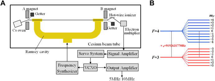
FIGURE 2. Principle of LIP Cs-3000 cesium atomic clock. (A) Schematic of LIP Cs-3000. (B) Cesium ground state sublevels in a magnetic field.
Performance and analysis
Important performance aspects of compact cesium atomic clocks include the stability and accuracy. The stability is the degree to which the atomic clock produces the same value of frequency throughout a specified time interval. The accuracy reflects the degree to which atomic clock output frequency agrees with the value corresponding to the definition of the SI second.
Stability
The frequency stability depends on the averaging time and on the Ramsey pattern of the cesium beam tube (CBT) of an atomic clock. The typical curve of Ramsey pattern of LIP Cs-3000 is shown in Figure 3. The curve can be described by three parameters including line width, peak-to-valley ratio and signal-to-noise ratio, which determine the Allan deviation
where
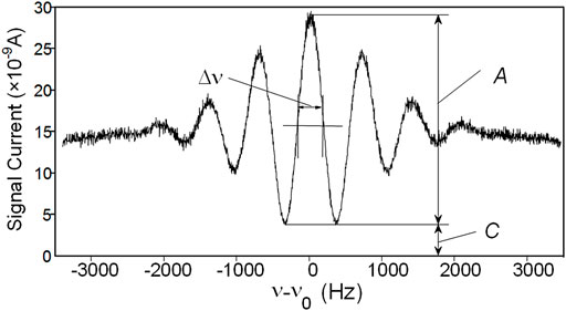
FIGURE 3. The Ramsey pattern of the CBT of LIP Cs-3000 (v0 = 9192631770 Hz).
The line width
where
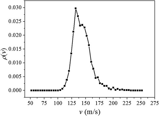
FIGURE 4. Velocity distribution of the signal atoms in CBT of LIP Cs-3000 clock.
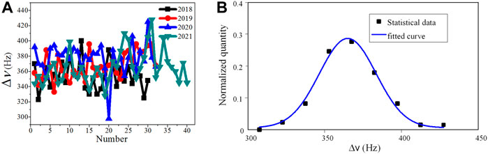
FIGURE 5. The line widths of CBTs. (A) Statistical chart of the line widths of CBTs from 2018 to 2021, and there are about 30 or 40 tubes every year considered. (B) Normal distribution fitting for line width of all tubes.
The peak-to-valley ratios of these clocks lie in the range of 2–13 in Figure 6. It can be seen that the peak-to-valley ratios approximately obey the Burr type XII distribution [16] with shape parameters of 0.8 and 7.0 and a scale parameter of 5.0 respectively. The peak-to-valley ratio of a cesium beam tube reveals the relative position of ionization detector (Hot-wire ionizer in Figure 2A) to the state-selection magnet where cesium atoms pass through. A higher peak-to-valley ratio represents a more accurate position of ionization detector where less cesium atoms without clock transition are collected. This wide distribution implies that the position of ionizer needs more accurate control in the manufacturing process.
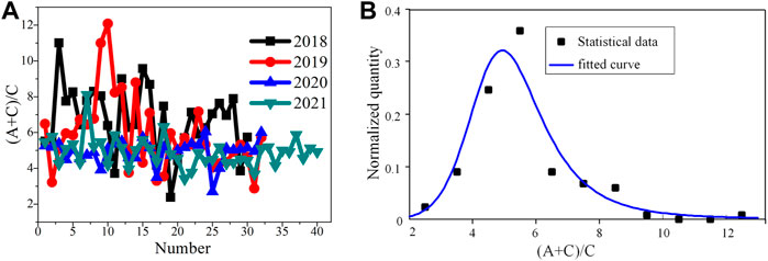
FIGURE 6. The peak-to-valley ratios of CBTs. (A) Statistical chart of the peak-to-valley ratios of CBTs from 2018 to 2021. (B) Burr type XII distribution fitting for the peak-to-valley ratios of all tubes.
The signal-to-noise ratio is the root mean square noise of the signal with 1 Hz bandwidth. Because square wave frequency modulation is employed near the central peak of Ramsey pattern, the signal of CBT is DC signal at each modulation frequency. The signal-to-noise ratio of the DC signal with noise depends on the bandwidth of measurement. The signal is filtered with the 1 Hz low pass filter centered at the frequency 0 Hz. In general, the signal-to-noise ratio increases with the increase of cesium oven temperature. For the convenience of comparison, we fixed the oven temperature at 110°C in the signal-to-noise ratio test of cesium beam tubes. The signal-to-noise ratio lies in 2,000–8,000 shown in Figure 7, which resulting in upmost predicted Allan deviation of less than
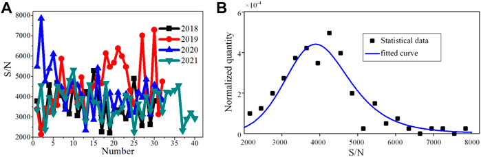
FIGURE 7. The signal-to-noise ratios of the CBTs. (A) Statistical chart of the signal-to-noise ratios of CBTs from 2018 to 2021. (B) Burr type XII distribution fitting for the signal-to-noise ratio of all tubes.
If we take
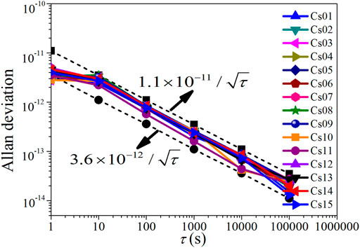
FIGURE 8. The Allan deviation data of LIP Cs-3000 atomic clocks. Csnn–LIP Cs-3000 clocks. The dotted lines are corresponding to
Accuracy
The accuracy of the LIP Cs-3000 clock is within the range of
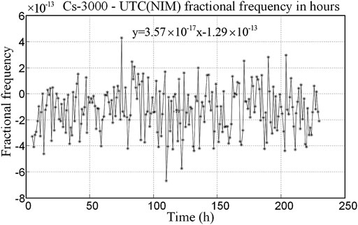
FIGURE 9. The fractional frequency of LIP Cs-3000 cesium atomic clock.
The second-order Zeeman frequency shift is given by [17].
where B is the C field and
The second-order Doppler effect originates from the time dilation phenomenon of relativity. For an atom of velocity
where c is the speed of light. Considering the velocities of the atoms are spread according to the distribution
The end-to-end cavity phase shift
where T is the transit time in the drift region between the cavity ends. The phase shift comes from the energy losses occurring in the cavity wall and in the two terminations and unequal lengths of the two cavity-arms. In general, the relative frequency shift amounts to the level of
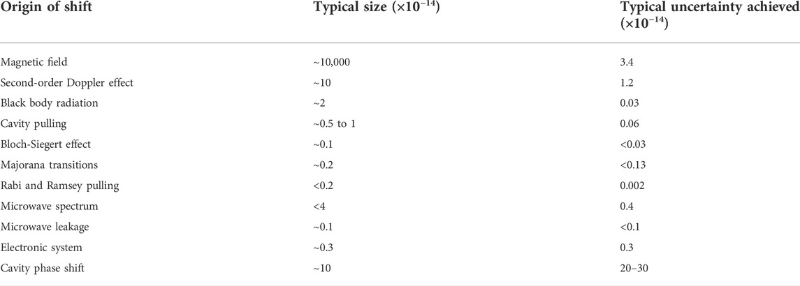
TABLE 1. Summary of frequency shifts and their uncertainties in LIP Cs-3000.
Lifetime evaluation
At present, the lifetime of LIP Cs-3000 cesium atomic clock is almost equal to that of electron multiplier. The multiplier is used to amplify the signal current of about 1 pA to tens or even hundreds of nA. However, this amplification ability will gradually decrease over time [19]. When it reduces to a certain extent, the life of multiplier, that is, the life of cesium clock, will end [20].
The lifetime of electron multiplier depends on two parameters called gain and decay rate of gain [21, 22]. The higher gain and lower decay rate of gain mean the longer lifetime of a electron multiplier. Gain is a multiple factor by which the electron multiplier amplifies the current signal. One of the characteristics of electron multiplier is that its gain value changes exponentially with the increase of the working voltage. Figure 10 shows the curve of the gain value of the electron multiplier of the LIP Cs-3000 clock changing with operating voltage. We can find from Figure 10 that under the working voltage of −2500 V, the gain value can reach
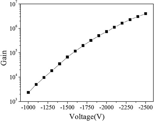
FIGURE10. The curve of the gain value of the electron multiplier changing with operating voltage.
To solve the deterioration problem, the function of automatically regulating the voltage of the electron multiplier is added into the circuit of LIP Cs-3000. When the gain of the multiplier varies, the circuit will changes its voltage accordingly to keep the current stable. Therefore, we can expect that as the gain continues to decrease, the voltage will continue to rise. It should be pointed out that in the initial stage of electron multiplier, one usually observes that the voltage does not increase but decreases (Figure 11). This is because at this stage, the dynode surface of the electron multiplier is covered with a layer of impurities, which will be gradually removed under the bombardment of electrons, so that the gain of the multiplier became higher and higher. This process lasts about 1 month to half a year.
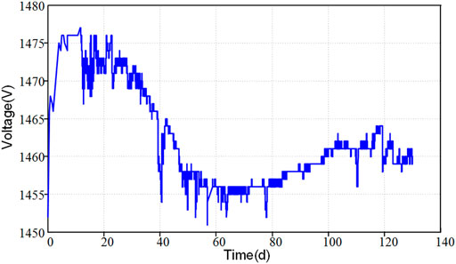
FIGURE11. The curve of the operating voltage of the electron multiplier with time in the early stage.
The added function that introduced to automatically regulate the voltage of the electron multiplier improves the long-term stability of the cesium atomic clock. In addition, it brings another advantage that the lifetime of an electron multiplier can be evaluated. When the cesium atomic clock enters the stable working stage, it can be observed that the voltage increases in a nearly linear form (see Figure 12). Consequently, as long as the daily voltage increase of a multiplier is measured, the lifetime of the multiplier can be calculated according to the following formula approximately
where
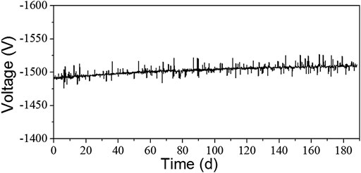
FIGURE12. The curve of the operating voltage of the electron multiplier with time after it enters the stable working stage.
If the initial stage life of the multiplier is considered, the lifetime Eq. 4 will be modified as follows
where
Environmental adaptability
In order to meet the requirements for the application of LIP Cs-3000 cesium clock in different environments, we have carried out a series of designs and tests on the environmental adaptability. These works ensure the quality characteristics of the clock in different environments during operation, transportation and storage. Up to now, the designs and tests are mainly related to mechanical vibration environment, thermal environment and electromagnetic field environment.
For the mechanical vibration environment, the finite element analysis method is adopted. The structure of the whole machine is analyzed, the weak area is found and the reinforcement is completed, highly reliable components of beam optics in CBT were designed. On this basis, a random vibration test with road-level was carried out with vibration frequency in the range of 10–500 Hz and the vibration order 1.04 g. As shown in Table 2, there is no significant change in the stability before and after the vibration test.
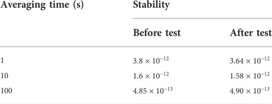
TABLE 2. Frequency stability before and after the random vibration test.
A variety of measures have been adopted in the thermal design. Using the thermal imaging technology, it was found that the module with the largest heat sources in a cesium atomic clock is the power supply. Thus the power supply module is installed on the side wall of the case to accelerate heat exchange. In addition, different passages of heat dissipation are designed in the clock. For example, the modules with high power such as microwave source and 1PPS source are also installed on the case wall, and the VCXO is positioned near CBT where temperature variation is relatively smaller. Meanwhile, the clock adopts constant-temperature VCXO with “SC-cut”, which has good temperature characteristics and small temperature coefficient. Therefore the clock can start up and operate normally after low and high temperature storage tests carried out at
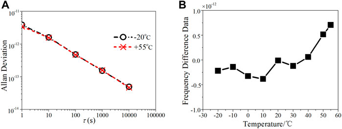
FIGURE 13. The frequency curves under the different working temperatures. (A) Frequency stability. (B) Relative frequency difference at different temperatures.
In terms of electromagnetic field environment, shielding technology is mainly used. By establishing the relation between magnetic sensitivity and permeability of magnetic shield in a cesium clock, a magnetic shield system with high permeability more than 150,000 is designed in CBT. As a result, the total shielding efficiency is greater than
Although the clock has passed the above tests, some other tests, such as drop, functional shock and temperature shock, need to be completed in the future. We expect that these new tests will help improve the adaptability of the clocks further and make the clocks be applied to the more complex environments such as vehicles and ships and so on.
Summary
This paper has studied and analyzed the performance of LIP Cs-3000 cesium clocks according to their technical characteristics and test data. The statistical data show that the range of value of line width, peak-to-valley ratio and signal-to-noise ratio of Ramsey pattern are 340–410 Hz, 2–13 and 2,000–8,000 respectively. These values assure that the Allan deviations of the clocks lies in the range of
Data availability statement
The original contributions presented in the study are included in the article/supplementary material, further inquiries can be directed to the corresponding author.
Author contributions
JC: conception and idea. JW: testing of CBT. LG: testing of electronic multiplier. JY: testing of environment. PM: testing of circuit. LH: pictures production. ZL: funding acquisition. Data analysis and writing of the paper by JC, JW, LG, JY, and PM.
Funding
National Defense Key Laboratory Stabilization Support Program of China under Grant No. HTKJ2020KL510006. National Natural Science Foundation of China under Grants No. 61971209.
Acknowledgments
The authors thank Professor Wang Yiqiu for his helpful discussions in developing LIP Cs-3000 clocks. The authors also thank the support from National Defense Key Laboratory Stabilization Support Program of China and National Natural Science Foundation of China.
Conflict of interest
The authors declare that the research was conducted in the absence of any commercial or financial relationships that could be construed as a potential conflict of interest.
Publisher’s note
All claims expressed in this article are solely those of the authors and do not necessarily represent those of their affiliated organizations, or those of the publisher, the editors and the reviewers. Any product that may be evaluated in this article, or claim that may be made by its manufacturer, is not guaranteed or endorsed by the publisher.
References
1.BIPM. BIPM annual report on time activities, volume 15 (2020). Available from: https://www.bipm.org/en/search?p_p_id=search_portlet&p_p_state=normal&p_p_mode=view&_search_portlet_javax.portlet.action=search&_search_portlet_source=BIPM&p_p_lifecycle=0 (Accessed April 24, 2022).
2. Yuan Hb., Qu LL, Dong SW, Li W, Zhang H. The hydrogen maser and cesium clocks in time keeping at NTSC. In: 2009 Joint Meeting of the European Frequency and Time Forum (EFTF'09) and the IEEE International Frequency Control Symposium (FCS'09) (2009). p. 639–42. doi:10.1109/FREQ.2009.5168261
3. Breakiron LA. Kalman filter characterization of cesium clocks and hydrogen masers. In: Proceedings of the 34th Annual Precise Time and Time Interval Systems and Applications Meeting (2002). p. 511–26. Available from: https://www.ion.org/publications/abstract.cfm?articleID=13966 (Accessed August 1, 2022).
4. Vannicola F, Beard R, White J, Seni K, Largay M, Buisson J. GPS block IIF atomic frequency standard analysis. In: 42nd Annual Precise Time and Time Interval (PTTI) Meeting (2010). p. 181–95. Available from: https://www.ion.org/publications/abstract.cfm?articleID=10732 (Accessed August 1, 2022).
5. Vannicola F, Beard R, Koch D, Kubik A, Wilson D, White J. GPS block IIF atomic frequency standard analysis. In: Proceedings of the 45th Annual Precise Time and Time Interval Systems and Applications Meeting (2013). p. 244–9. Available from: https://www.ion.org/publications/abstract.cfm?articleID=11597 (Accessed August 1, 2022).
6. Vanier J, Audoin C. The quantum Physics of atomic frequency standards. New York: Adam Hilger (1989). Available from: http://www.crcpress.com/The-Quantum-Physics-of-Atomic-Frequency-Standards/Vanier-Audoin/p/book/9781420050851 (Accessed August 1, 2022).
7.Fritz Riehle. Frequency standards: Basics and applications. Weinheim: WILEY-VCH Verlag GmbH (2004). doi:10.1109/MIM.2005.1578626
8.Microchip. Microchip (2022). Available from: https://www.microsemi.com/document-portal/doc_download/133269-5071a-datasheet (Accessed August 1, 2022).
9.Oscilloquartz. Oscilloquartz (2022). Available from: https://www.oscilloquartz.com/en/resources/downloads/data-sheets/osa-3235b-cesium-clock (Accessed August 1, 2022).
10. Chen J, Ma P, Wang J, Guo L, Liu ZD, Yang J, et al. Progress in commercialization of compact magnetically selected cesium atomic clocks. J Astronautic Metrology Meas (2020) 40(3):12–6. doi:10.12060/j.issn.1000-7202.2020.03.03
11. Chen J, Ma P, Wang J, Guo L, Tu JH, Yang W. Test of magnetic-selected cesium atomic clock LIP Cs3000C. J Time Frequency (2018) 41(3):190–3. doi:10.13875/j.issn.1674-0637.2018-03-0190-04
12. Cutler LS. Fifty years of commercial caesium clocks. Metrologia (2005) 42(3):90–9. doi:10.1088/0026-1394/42/3/S10
13. Wang YQ, Wang QJ, Fu JS, Dong TQ. The theory of frequency standards. Beijing: Science Press (1986). p. 168–73.
14. Sullivan DB, Bergquist JC, Bollinger JJ, Drullinger RE, Itano WM, Jefferts SR, et al. Primary atomic frequency standards at NIST. J Res Natl Inst Stand Technol (2001) 106(1):47. doi:10.6028/jres.106.004
15. Lombardi MA, Heavner TP, Jefferts SR. NIST primary frequency standards and the realization of the SI second. NCSLI Measure (2007) 2(4):74–89. doi:10.1080/19315775.2007.11721402
16. Burr IW. Cumulative frequency functions. Ann Math Statist (1942) 13(2):215–32. doi:10.1214/aoms/1177731607
17. Vanier J, Audoin C. The classical caesium beam frequency standard: Fifty years later. Metrologia (2005) 42(3):31–42. doi:10.1088/0026-1394/42/3/S05
18. Audoin C, Dimarcq N, Giodano V, Viennet J. Physical origin of the frequency shifts in cesium beam frequency standards-related environmental sensitivity. IEEE Trans Ultrason Ferroelectr Freq Control (1992) 39(3):412–21. doi:10.1109/58.143175
19. Hirashima M, Miyashiro S. Some factors affecting the decay of secondary electron emission of silver-magnesium alloys. J Phys Soc Jpn (1957) 12(7):770–7. doi:10.1143/JPSJ.12.770
20. Brock C, Tolman BW, Taylor RE. End-of-life indicators for nima's high-performance cesium frequency standards. In: Proceedings of the 34th Annual Precise Time and Time Interval Systems and Applications Meeting (2002). p. 117–26. Available from: https://www.ion.org/publications/abstract.cfm?articleID=13932 (Accessed August 1, 2022).
21. Straka ER. Performance characteristics of cesium beam tube electron multipliers. In: 36th Annual Frequency Control Symposium (1982). p. 230–5. doi:10.1109/FREQ.1982.200575
22. Kusters JA, Cutler LS, Powers ED. Long-term experience with cesium beam frequency standards. In: 1999 Joint Meeting EFTF - IEEE IFCS (1999). p. 159–63. doi:10.1109/FREQ.1999.840733
23.GJB-151B. Electromagnetic emission and susceptibility requirements and measurements for military equipment and subsystems (2013). p. 12–80. Available from: http://www.bzko.com/std/201059.html (Accessed August 1, 2022).
Keywords: cesium atomic clock, cesium beam tube, accuracy, stability, ramsey pattern, electron multiplier
Citation: Chen J, Wang J, Guo L, Yang J, Ma P, Huang L and Liu Z (2022) Characteristics analysis of compact cesium atomic clock with magnetic state selection. Front. Phys. 10:959343. doi: 10.3389/fphy.2022.959343
Received: 01 June 2022; Accepted: 18 July 2022;
Published: 02 September 2022.
Edited by:
Xuzong Chen, Peking University, ChinaCopyright © 2022 Chen, Wang, Guo, Yang, Ma, Huang and Liu. This is an open-access article distributed under the terms of the Creative Commons Attribution License (CC BY). The use, distribution or reproduction in other forums is permitted, provided the original author(s) and the copyright owner(s) are credited and that the original publication in this journal is cited, in accordance with accepted academic practice. No use, distribution or reproduction is permitted which does not comply with these terms.
*Correspondence: Jiang Chen, Y2hlcm5qaWFuZ0BhbGl5dW4uY29t