 Shuang Liu
 Yin Li2*
 Xiao Zhang
 Shiyan Wang
- 1College of Mathematics and Physics, Chengdu University of Technology, Chengdu, China
- 2Peng Cheng Laboratory, Shenzhen, China
- 3The College of Electronics and Information Engineering, Shenzhen University, Shenzhen, China
- 4Jiangsu Key Laboratory of 3D Printing Equipment and Manufacturing, Nanjing Normal University, Nanjing, China
- 5AVIC Research Institute for Special Structures of Aeronautical Composites, Jinan, China
- 6Department of Mechanical Engineering, Southeast University, Nanjing, China
This work proposes a low-profile circularly polarized folded reflectarray antenna (CPFRA). Compared to traditional CPFRA that comprise the main reflectarray, a polarization grid (PG), and a linear-to-circular polarization (LP-CP) converter, the proposed CPFRA utilizes a polarization-sensitive LP-CP converter that plays the roles of both PG and LP-CP converter to minimize the CPFRA profile. One period of the polarization-sensitive LP-CP converter consists of an LP and a CP patch on the bottom and top layer of the substrates, respectively, which are connected by a metalized via. Due to its frequency-selective characteristic, the polarization-sensitive LP-CP surface can simultaneously reflect the x-polarized waves and transfer the received y-polarized waves into the CP state. A 1-bit unit cell at the bottom layer is adopted for polarization conversion and phase shift. A planar patch antenna is integrated as the primary feeding source. A high-gain circularly polarized folded reflectarray antenna at the X-band is designed, fabricated, and measured. Both simulated and measured results demonstrate the advantages of high gain and a lower profile of the proposed CPFRA compared to those in its traditional counterparts.
Introduction
Printed reflectarrays (RAs) consist of numerous planar elements for phase compensation and a feeding source assembled over the planar elements at some distance. RA development has attracted increased attention in recent years due to the high gain, planar structure, and cost-effectiveness of RAs compared to traditional reflector antennas [1–6]. However, the common RA design has a high profile, including a bulky feeding horn and a distance between the feeding source and array that depends on the focal-length-to-diameter (F/D). The use of a low-profile antenna as the feeding source can reduce the overall profile [7, 8]. A folded reflectarray (FRA) was proposed to reduce the RA profile [9–14]. The FRA consists of a main reflectarray and a polarizer grid (PG) where the incident wave is reflected in one polarization and transmitted in the other polarization. The main reflectarray provides a phase shift to the suitable phase in the farfield zone and twists the polarization by 90°. Compared to that of traditional RAs, the profile of FRAs is reduced by one-half focal length (F). Based on this low-profile feature, various FRAs have been designed. The wideband polarization rotating metasurface (PRM) was used to design the wideband FRA [14–16]. Moreover, a sub-wavelength element was also used to improve RFA bandwidth [17]. A dual-band FRA was proposed for the downlink and uplink of VSAT links [18]. For beam-scanning applications, FRAs have been developed with reconfigurable beams [10, 19]. An FRA with a high-gain filtering function was recently reported [20], in which a polarization-sensitive frequency-selective surface (FSS) was used to replace the polarization grid of the transitional RFA.
Satellite communications demand high-performance antennas with high gain that are also circularly polarized (CP) and with a low profile [21]. CP RAs with high profiles were proposed in earlier works [22, 23]. FRAs can easily realize the high-gain and CP performance. Unfortunately, CPFRA is hard to realize as the polarization-selective polarization grid (PG) is on the top layer of FRAs. Metasurfaces can powerfully manipulate electromagnetic waves, including those of polarization, with easy fabrication and low costs [24–28]. Therefore, there is a simple method to design the CP antenna by locating the LP-CP converter or metasurface on the LP antenna [29–31]. Recently, CPFRA was achieved by locating the LP-CP converter on the top layer, with a suitable distance to the PG [32, 33], which increased both the FRA profile and assembly complexity.
The present work describes a polarization-sensitive LP-CP converter with a dual function to replace the PG and traditional LP-CP [32, 33]. The planar antenna is integrated as a primary source. Compared to traditional FRAs, it showed satisfactory performance with a lower profile.
Antenna design
Design concept
As shown in Figure 1A, the traditional CPFRA is composed of the polarization-insensitive LP-CP converter on the top layer to covert the LP plane wave to the CP wave. The main reflectarray can twist the x-polarized wave to y-polarization. The phase compensation is also provided by the main reflectarray for the focusing director, transforming the spherical wave into a plane wave. The distance between the PG and the LP-CP converter should be carefully selected for optimal performance. Nevertheless, the profile is inevitably increased as a consequence. To reduce the profile, the dual functions of LP-CP and PG can be integrated by a polarization-sensitive LP-CP converter, as shown in Figure 1B.
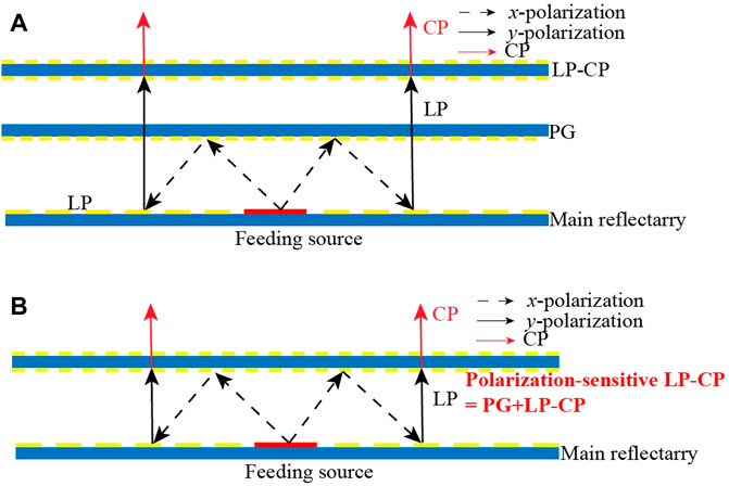
FIGURE 1. Topology of traditional and proposed CPFRAs. (A) Traditional CPFRA. (B) Proposed CPFRA.
Design of the polarization-sensitive LP-CP converter
The unit cell of the LP-CP converter is shown in Figure 2. It consisted of an LP and a CP patch that are connected to a metalized via-hole. Both patches and the ground layer are printed on surfaces of two substrates (Rogers 4003C) with a height of 1.524 mm, a relative permittivity of 3.5, and a loss tangent of 0.0027. The prepreg RO4450F with a relative permittivity of 3.7 and a thickness of 0.1 mm is adopted between the two dielectric substrates for integrated design. The top-layer metallic structure is shown in Figure 2B. Two corners of the patch are truncated, and one slot is embedded to separate two degenerate modes for CP radiation. As shown in Figure 2C, a circular clearance is used to void the metalized via-hole connecting to the ground. An LP patch with two slots is etched on the bottom layer for receiving LP waves, as shown in Figure 2D. The LP and CP patches and their interconnection work in an antenna-filter-antenna topology. It can receive the LP wave from the main reflectarray on the bottom layer and then transmit it to the CP patch on the top layer.
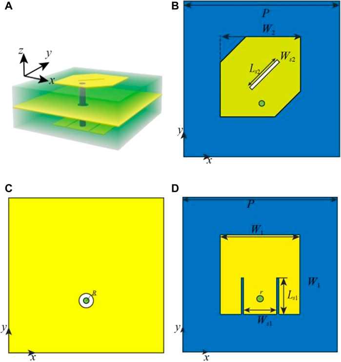
FIGURE 2. Layout of the polarization-sensitive LP-CP converter. (A) Perspective view. (B) Top layer. (C) Middle layer. (D) Bottom layer. The dimensions of the converter are W1 = 7.2 mm, W2 = 7.2 mm, Ws1 = 3 mm, Ls1 = 3.3 mm, r = 0.3 mm, R = 0.7 mm, Ws2 = 0.3 mm, Ls2 = 3.5 mm, p = 14 mm.
The CST-WMS with periodic boundary conditions was used to study the properties of the unit cell. Figure 3 shows the reflection coefficients of the polarization-sensitive LP-CP converter under different oblique incidences with x-polarization. The reflection coefficients (Rxx) were larger than -0.5 dB under different incident angles in the X-band. Therefore, the polarization-sensitive LP-CP converter can fully replace the PG, reflecting most of the incident waves with x-polarization. Figure 4 shows the reflection coefficients and axial ratios (ARs) under normal incidence waves with y-polarization, demonstrating a reflection coefficient better than −10 dB at 9.3–10.5 GHz. Figure 5A shows the transmission coefficients of the unit cells under the incidence wave with y-polarization. The magnitudes of Txy and Tyy were −3.3 dB, with a phase difference of 90°at 10.1 GHz; thus, a circular polarization wave was obtained with the y-polarization incident wave at approximately 10.1 GHz. As shown in Figure 5B, the polarization efficiency of y-polarization to left-handed circular polarization (LHCP) was >0.94 at 9.8–10.3 GHz. Therefore, the polarization-sensitive LP-CP converter effectively performed the functions of the PG and the polarization-insensitive LP-CP converter. The physical properties of the LP-CP converter can be described by the ellipticity and azimuth rotation angle, as defined by [34]:
where T++, T-- are the transmission coefficients for RHCP and LHCP waves, respectively. The ellipticity and azimuth rotation angle of the proposed LP-CP converter under the normal incident wave are plotted in Figure 6. The ellipticity and azimuth rotation angle are 45º and 180º at 10.1GHz, respectively, which represent a pure CP radiating wave. This result is inconsistent with that shown in Figure 5B.
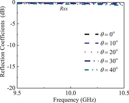
FIGURE 3. Simulated reflect coefficients of the polarization-sensitive LP-CP converter excited by x-polarized wave at different incidence angles.
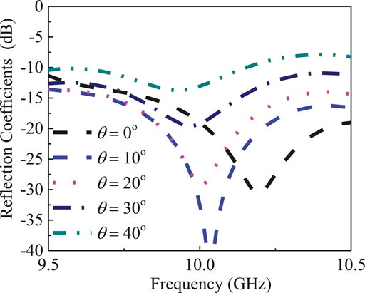
FIGURE 4. Simulated reflection coefficient of the polarization-sensitive LP-CP converter excited by y-polarized wave at different incidence angles.
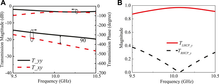
FIGURE 5. Simulated transmission coefficient and phase of the proposed unit cell. (A) Transmission coefficient and phase of x- and y-polarization under normal incident waves with y-polarization. (B) Transmission magnitudes of LHCP and RHCP under normal incident waves with y-polarization.
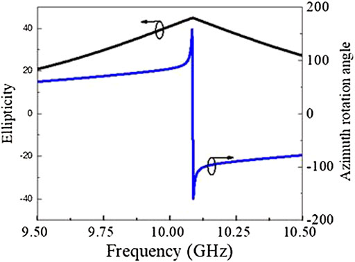
FIGURE 6. Ellipticity and azimuth rotation angle of the LP-CP converter.
1-Bit phase shift unit cell with 90-degree polarization twisting
An easily designed 1-bit unit cell is used in the main reflectarray to provide phase compensation and polarization twisting. The geometry of the 1-bit phase shift unit cell for the main reflectarray is shown in Figures 7A,B. The two states of unit cells were designed based on the Rogers 4003, with a thickness of 1.524 mm and a relative permittivity of 3.55. The 0°-state unit cell consisted of a circular patch with a stub, rotating 45°anticlockwise. The 180°-state unit cell was obtained by rotating the 0°-state unit cell clockwise by 90°. According to the theory in [35], a 180° phase difference exists between the two states. The simulated S-parameters of the two-state unit cells are plotted in Figure 7C. The reflection coefficients of the two unit cells under the normal incidence wave with x-polarization (Rxx) are better than −10 dB and the transmission coefficients of x-to y-polarization (Ryx) are approximately −0.25 dB in the range of 9.5–10.42 GHz. The simulated phase of the two-unit cells is shown in Figure 7D, with a phase difference of 180°. To analyze the angle stability, the reflection and transmission coefficients of unit cells were simulated under an oblique incident wave at 30° (Figure 7E,F). Figures 7E,F shows that the reflection coefficients are also better than −10 dB, while the phase difference of the two units maintains the stability of 180° at the operating frequency band.
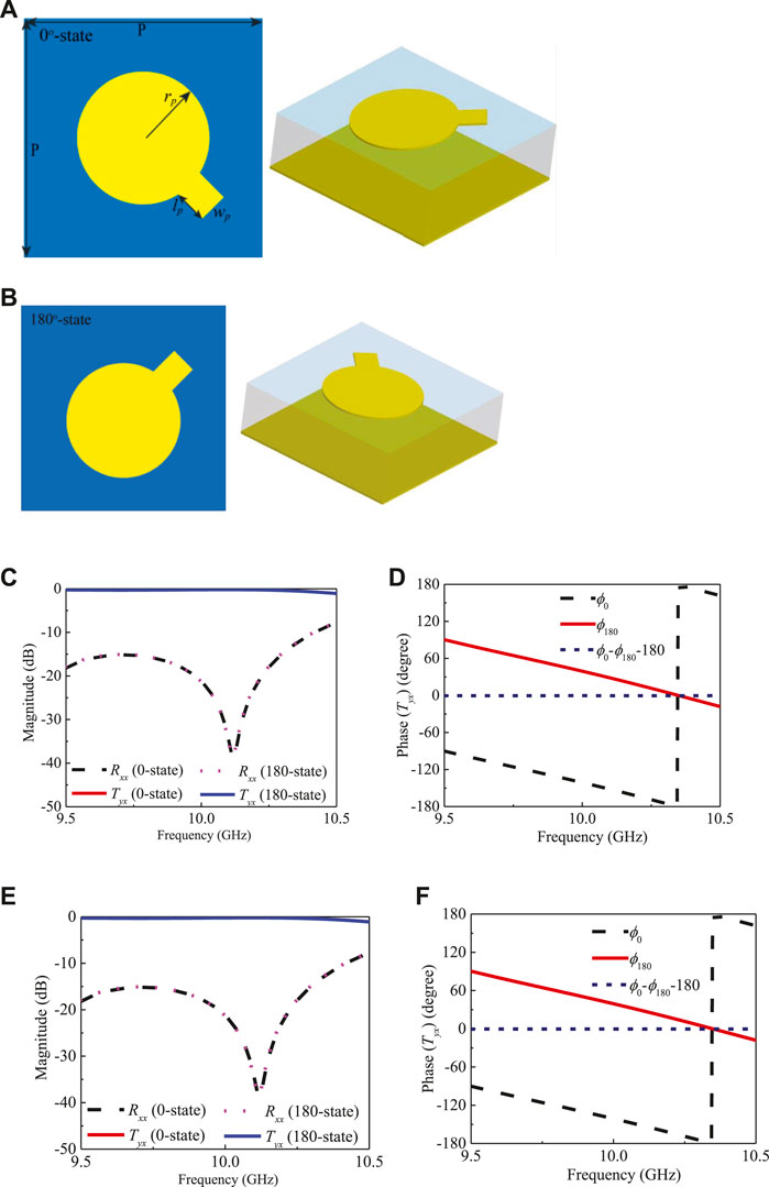
FIGURE 7. Geometry and simulated S-parameters of the 1-bit unit cell. (A) Layout of the 0°-state unit cell. (B) Layout of the 180°-state unit cell. (C) Reflection and transmission coefficients of the two unit cells under normal incident waves. (D) Phase difference under normal incident waves. (E) Reflection and transmission coefficients of the two unit cells under 30° oblique incident waves. (F) Phase difference under 30° oblique incident waves. The dimensions are p = 14 mm, Wp = 1.8 mm, Lp = 2.1 mm.
Design of the circularly polarized folded reflectarray antenna
As shown in Figures 8A, a low-profile and wideband microstrip antenna coupled with parasitic patches was designed as the primary source [36] and could be easily integrated into the bottom layer of the main reflectarray. The total size of the feeding source, replacing the area of 3 × 2 unit cells of the main reflectarray, was 42 mm × 28 mm. A coaxial probe was used to excite the microstrip antenna. The layout and dimensions of the microstrip antenna are also shown in Figure 8A. Simulated |S11| is shown in Figure 8B, while the normalized radiation pattern at 10.1 GHz is shown in Figure 8C. The microstrip antenna was well matched from 9 to 10.5 GHz, with an |S11| below −10 dB.
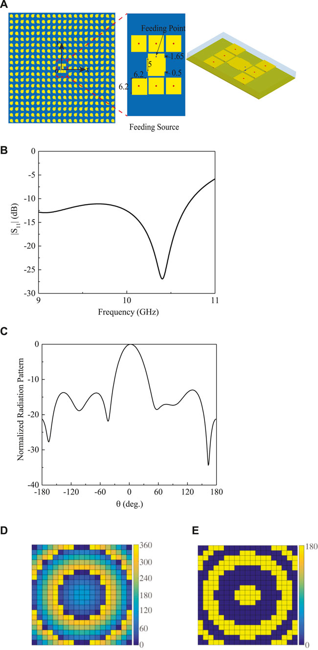
FIGURE 8. (A) Layout of the main reflect array with planar feeding source. (B) Simulated S-parameter of the feeding antenna. (C) Radiation pattern of the feeding antenna at 10.1 GHz. (D) Calculated phase distribution the proposed CPFRA at 10.1 GHz. (E) Discretized phase distribution.
The main reflect array consists of 19 × 20 elements and a total size of 266 mm × 280 mm. The focal-length-to-diameter (F/D) was set to 0.96, with the distance between the main reflectarray at the bottom layer and the LP-CP converter at the top layer set to half of the focal length. The total height of the antenna was 139.78 mm (NC43JiN4MDAzYmI7QDEwR0h6), while the distance between the main reflectarray at the bottom layer and the LP-CP converter at the top layer was 135 mm. As shown in Figure 8D, the direction of the CPFRA radiation beam xwas along the z-axis. The phase distributions of the main reflectarray are shown in Figure 8D. To implement the phase shown in Figure 8D by using the 1-bit unit cell, it is discretized by using the two-phase states of 0° and 180°. The discretized phase distribution is illustrated in Figure 8E.
Fabrication and measurements
Figure 9A shows the CPFRA prototype. Four plastic columns are used to support the main reflectarray at the bottom layer and the polarization-sensitive LP-CP converter. The feeding source of the microstrip antenna is located at the center of the main reflectarray with the phase implemented, as shown in Figure 9B. The top and bottom sides of the LP-CP converter are shown in Figures 9C and D, respectively. As shown in Figure 10A, the simulated and measured |S11| are better than −10 dB. Due to the fabrication tolerance, a tiny frequency shift of reflection zero is observed between these two results. The measured gain was approximately 21 dBic, which is close to the simulated result with a modest gain loss (Figure 10B). The measured and simulated ARs are also plotted in Figure 10B. A frequency shift was observed between the measured and simulated results. The simulated −3 dB AR bandwidth was 9.8–10.3 GHz. The simulated and measured normalized radiation patterns of the CPFRA at 10 GHz in xz- and yz-plane are plotted in Figure 11. The simulated and measured LHCP radiation patterns were consistent with each other in these planes. Finally, the normalized radiation gain of the RHCP (cross-polarization) was less than −15 dB.
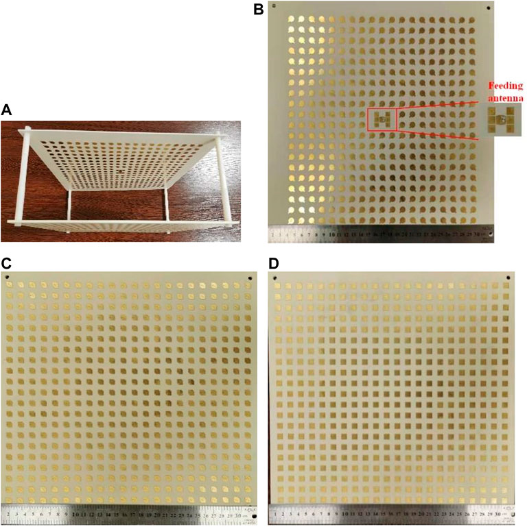
FIGURE 9. Prototype of the proposed CPFRA. (A) Perspective view. (B) Top view of the bottom layer. (C) Top view of the LP-CP converter. (D) Bottom view of the LP-CP converter.
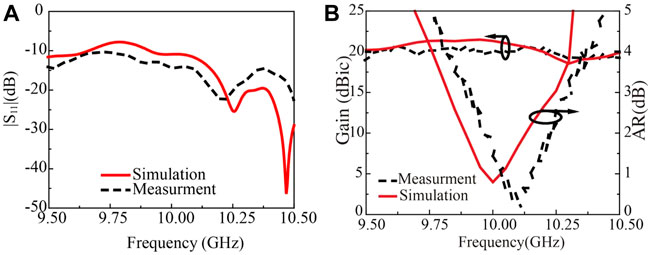
FIGURE 10. (A) Measured and simulated |S11| of the proposed CP-FRA. (B) Measured and simulated gain and AR.
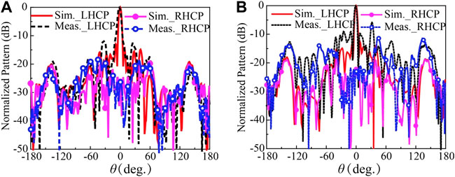
FIGURE 11. Simulated and measured normalized radiation patterns of the CP-FRA in the xz- and yz-planes. (A) Radiation patterns in the xz-plane. (B) Radiation patterns in the yz-plane.
The results of performance comparisons between other CP reflectarrays (CP-RA) and the CPFRA are shown in Table 1. Compared to the CPFRA in [32], the device described in the present work reduced the number of layers from three to two. Moreover, the height over the diameter was 0.47 in the present study, which was smaller than that of 0.87 in [32]. Compared to the CP-RA in [22, 23], the profile was effectively reduced. Therefore, the results of this study demonstrated the successful development of a low profile.
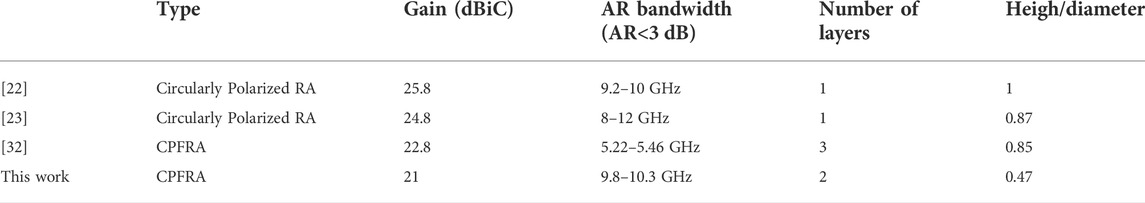
TABLE 1. Performance comparisons of other similar antennas.
Conclusion
This work proposed a low-profile CPFRA using a polarization-sensitive LP-CP converter to replace PG and polarization-insensitive LP-CP converters. This highly integrated design reduced the profile with a simple design process. The CP and LP patch antenna elements were connected by a metallic via at the two surfaces to provide the functions of LP-CP transformation. As the LP antenna elements can only transmit waves of specified polarization, the converter was polarization-sensitive. The main reflectarray consisted of 1-bit unit cells that provided 90-degree polarization twisting and 0 and 180-degree phase shifting. Both simulated and measured results demonstrated the effectiveness of the proposed CPFRA. This design concept can be used to develop high-performance CPFRA with wideband high-gain and low profile by using a wideband polarization-insensitive LP-CP converter.
Data availability statement
The original contributions presented in the study are included in the article/supplementary material. Further inquiries can be directed to the corresponding author.
Author contributions
SL is responsible for the entire study. YL contributed to the data curation, study methodology, and results validation. S-WW, XZ, and SW contributed to the study methodology and results validation. LF and QG mainly contributed to the data curation.
Funding
This work was supported by the Backbone Teachers Program (grant 10912-JXGG2021-06751), grant SWPTJG2102, the National Natural Science Foundation of China (grants 62101271 and 62171289), the Major Key Project of the PCL (PCL2021A15), Shenzhen Science and Technology Programs (grant JCYJ20190808145411289), the Guangdong Basic and Applied Basic Research Foundation (grant 2019A1515111166), the Natural Science Foundation of Jiangsu Province for Youth (grant BK20210557), and the Shenzhen Science and Technology Innovation Commission under the Shenzhen Fundamental Research Program (grant JCYJ20190808115411853).
Conflict of interest
The authors declare that the research was conducted in the absence of any commercial or financial relationships that could be construed as a potential conflict of interest.
Publisher’s note
All claims expressed in this article are solely those of the authors and do not necessarily represent those of their affiliated organizations, or those of the publisher, the editors, and the reviewers. Any product that may be evaluated in this article, or claim that may be made by its manufacturer, is not guaranteed or endorsed by the publisher.
References
2. Javor RD, Kai Chang XD, Chang K. Design and performance of a microstrip reflectarray antenna. IEEE Trans Antennas Propagat (1995) 43(9):932–9. doi:10.1109/8.410208
3. Huang J. Bandwidth study of microstrip reflectarray and a novel phased reflectarray concept. Proc IEEE Int Symp Antennas Propag (1995) 1:582.
4. Abd-Elhady M, Hong W, Zhang Y, Kishk A. W-band mutlilayer perforated dielectric substrate lens. IEEE Antennas Wirel Propag Lett (2014) 13:734.
5. Abd-Elhady M, Yan Zhang W, Zhang Y. A ka-band reflectarray implemented with a single-layer perforated dielectric substrate. Antennas Wirel Propag Lett (2012) 11:600–3. doi:10.1109/lawp.2012.2201128
6. Mahmoud AAK, Hao ZZ, Hong W. Ka-band circularly polarized reflectarray: Using a double-layers cross slot. IEEE Antennas Propag Mag (2016) 58(4):60–8. doi:10.1109/map.2016.2569428
7. Wu Q, Hirokawa J, Yin H, Yu C, Wang W, Hong W. Millimeter-wave planar broadband circularly polarized antenna array using stacked curl elements. IEEE Trans Antennas Propagat (2017) 65(12):7052–62. doi:10.1109/tap.2017.2766456
8. Jazi MN, Chaharmir MR, Shaker J, Sebak AR. Broadband transmitarray antenna design using polarization-insensitive frequency selective surfaces. IEEE Trans Antennas Propag (2016) 64(1):99.
9. Menzel DW, Menzel W. Folded reflectarray antenna. Electron Lett (1998) 34(9):832. doi:10.1049/el:19980670
10. Menzel W, Pilz D, Al-Tikriti M. Millimeter-wave folded reflector antennas with high gain, low loss, and low profile. IEEE Antennas Propag Mag (2002) 44(3):24–9. doi:10.1109/map.2002.1028731
11. Yang JW, Shen YZ, Wang L, Meng H, Dou W, Hu SM. 2-D scannable 40-GHz folded reflectarray fed by SIW slot antenna in single-layered PCB. IEEE Trans Microwave Theor Techn. (2018) 66(6):3129–35. doi:10.1109/tmtt.2018.2818698
12. Shen YZ, Yang JW, Meng HF, Dou WB, Hu SM. Generating millimeter-wave Bessel beam with orbital angular momentum using reflective-type metasurface inherently integrated with source. Appl Phys Lett (2018) 112(14):141901. doi:10.1063/1.5023327
13. Jiang M, Hong W, Zhang Y, Zhou SH, Zhou H. A folded reflectarray antenna with a planar SIW slot array antenna as the primary source. IEEE Trans Antennas Propagat (2014) 62(7):3575–83. doi:10.1109/tap.2014.2317485
14. Qu S-W, Zhang H-X, Wu W-W, Li P-F, Yang S, Nie Z-P. Wideband folded reflectarray using novel elements with high orthogonal polarization isolation. IEEE Trans Antennas Propagat (2016) 64(7):3195–200. doi:10.1109/tap.2016.2565679
15. Cao Y, Che W, Yang W, Fan C, Xue Q. Novel wideband polarization rotating metasurface element and its application for wideband folded reflectarray. IEEE Trans Antennas Propagat (2020) 68(3):2118–27. doi:10.1109/tap.2019.2948525
16. Su W, Luo W, Nie Z, Liu W-W, Cao Z-H, Wang Z. A wideband folded reflectarray antenna based on single-layered polarization rotating metasurface. IEEE Access (2020) 8:158579–84. doi:10.1109/access.2020.3019822
17. Guo L, Tan P-K, Chio T-H. On the use of single-layered subwavelength rectangular patch elements for broadband folded reflectarrays. Antennas Wirel Propag Lett (2017) 16:424–7. doi:10.1109/lawp.2016.2582201
18. Menzel J, Menzel W. Dual-frequency folded reflectarray antenna. Antennas Wirel Propag Lett (2013) 12:1216–9. doi:10.1109/lawp.2013.2283085
19. Wang Z, Ge Y, Pu J, Chen X, Li G, Wang Y, et al. 1 bit electronically reconfigurable folded reflectarray antenna based on p-i-n diodes for wide-angle beam-scanning applications. IEEE Trans Antennas Propagat (2020) 68(9):6806–10. doi:10.1109/tap.2020.2975265
20. Zhu X -C, Zhang P -P, Zhang Y -X, Ge J -X, Gao Z -H. A high-gain filtering antenna based on folded reflectarray antenna and polarization-sensitive frequency selective surface. Antennas Wirel Propag Lett (2020) 19(8):1462–5. doi:10.1109/lawp.2020.3007540
22. Zhao G, Jiao Y, Zhang F, Zhang F. A subwavelength element for broadband circularly polarized reflectarrays. Antennas Wirel Propag Lett (2010) 9:330–3. doi:10.1109/lawp.2010.2047836
23. Momeni Hasan Abadi SMA, Behdad N. Broadband true-time-delay circularly polarized reflectarray with linearly polarized feed. IEEE Trans Antennas Propagat (2016) 64(11):4891–6. doi:10.1109/tap.2016.2596900
24. Li SJ, Li YB, Zhang L, Luo ZJ, Han BW, Li RQ, et al. Programmable controls to scattering properties of a radiation array. Laser Photon Rev (2021) 15(2):2000449. doi:10.1002/lpor.202000449
25. Li SJ, Li YB, Li H, Wang ZX, Cui TJ. A thin selfeeding janus metasurface for manipulating incident waves and emitting radiation waves simultaneously. Weinheim: Annalen der Physik (2020).
26. Li ZY, Li SJ, Han BW, Huang GS, Guo ZX, Cao XY. Quad-band transmissive metasurface with linear to dual‐circular polarization conversion simultaneously. Adv Theor Simul. (2021) 4(8):2100117. doi:10.1002/adts.202100117
27. Han B, Li S, Li Z, Huang G, Tian J, Cao X. Asymmetric transmission for dual-circularly and linearly polarized waves based on a chiral metasurface. Opt Express (2020) 29:19643.
28. Long F, Yu S, Yang Z, Li X, Ding Z, Zhang Z. Broadband linear-to-circular polarization reflector using anisotropic metasurface. Int J RF Microw Comput Aided Eng (2021) 31(7):22697. doi:10.1002/mmce.22697
29. Winkler SA, Wei Hong W, Bozzi M, Ke Wu K. Polarization rotating frequency selective surface based on substrate integrated waveguide Technology. IEEE Trans Antennas Propagat (2010) 58(4):1202–13. doi:10.1109/tap.2010.2041170
30. Muhammad SA, Sauleau R, Legay H. Purely metallic waveguide-fed fabry-perot cavity antenna with a polarizing frequency selective surface for compact solutions in circular polarization. Antennas Wirel Propag Lett (2012) 11:881–4. doi:10.1109/lawp.2012.2210693
31. Xie P, Wang G, Li H, Liang J, Gao X. Circularly polarized Fabry-Perot antenna employing a receiver-transmitter polarization conversion metasurface. IEEE Trans Antennas Propagat (2020) 68(4):3213–8. doi:10.1109/tap.2019.2950811
32. Zhang C, Wang Y, Zhu F, Wei G, Li J, Wu C, et al. A planar integrated folded reflectarray antenna with circular polarization. IEEE Trans Antennas Propag (2016) 65(1):385.
33. Yu Z, Zhang Y. A planar integrated beam scanning folded reflectarray with circular polarization for millimeter-wave applications. In: IEEE MTT-S inter. Microw. Workshop series on adv. Materials and processes for RF and THz applications. Suzhou: IMWS-AMP (2020). p. 1. doi:10.1109/imws-amp49156.2020.9199746
34. Prajapati PPR, Prajapati PR. Design of circular polarized antenna using gammadion chiral metamaterial as linear-to-circular polarization transformer. Pier M (2020) 96:69–78. doi:10.2528/pierm20061806
35. Pogorzelski JRJ, Pogorzelski RJ. A Ka-band microstrip reflectarray with elements having variable rotation angles. IEEE Trans Antennas Propagat (1998) 46:650–6. doi:10.1109/8.668907
Keywords: polarization-sensitive, linear-to-circular polarization (LP-CP) converter, circular polarization, folded reflectarray antenna (FRA), low-profile
Citation: Liu S, Li Y, Wong S-W, Zhang X, Wang S, Fang L and Gao Q (2022) A circularly polarized folded reflectarray antenna using a polarization-sensitive linear-to-circular polarization converter. Front. Phys. 10:983951. doi: 10.3389/fphy.2022.983951
Received: 01 July 2022; Accepted: 09 August 2022;
Published: 09 September 2022.
Edited by:
Yu Luo, Tianjin University, ChinaReviewed by:
Neng-Wu Liu, Xidian University, ChinaLiang Hua Ye, Guangdong University of Technology, China
Copyright © 2022 Liu, Li, Wong, Zhang, Wang, Fang and Gao. This is an open-access article distributed under the terms of the Creative Commons Attribution License (CC BY). The use, distribution or reproduction in other forums is permitted, provided the original author(s) and the copyright owner(s) are credited and that the original publication in this journal is cited, in accordance with accepted academic practice. No use, distribution or reproduction is permitted which does not comply with these terms.
*Correspondence: Yin Li, bGl5MTdAcGNsLmFjLmNu