 Andrea Uccello*
 William Bin
 Alessandro BruschiFederica Causa
 Anna CremonaMarco De AngeliDaniela FarinaGiuseppe GattoGabriele GervasiniFrancesco GhezziGiuseppe GittiniGustavo GranucciGiovanni GrossoLaura LaguardiaMaurizio LontanoVittoria MelleraDaniele Minelli
 Antonio NardoneMatteo PedroniFederico RipamontiNatale Rispoli
 Espedito VassalloDaria Ricci
- Istituto per la Scienza e Tecnologia dei Plasmi, Consiglio Nazionale delle Ricerche, Milan, Italy
GyM is a linear plasma device operating at Istituto per la Scienza e Tecnologia dei Plasmi, Consiglio Nazionale delle Ricerche, Milan, with the original aim of studying basic plasma physics, such as turbulent processes. Since 2014, GyM experimental program has been mainly focused on the issue of plasma-material interaction (PMI) for magnetic confinement nuclear fusion applications. GyM consists of a stainless steel vacuum chamber (radius and length of 0.125 m and 2.11 m), a pumping system, a gas injection system, 10 magnetic field coils and two magnetron sources at 2.45 GHz, capable of delivering a total microwave power up to 4.5 kW. Highly reproducible steady-state plasmas of different gas species, at a maximum working pressure of
1 Introduction
Plasma-wall interaction (PWI) is one of the most critical issues with respect to the performance, safety and availability of future fusion reactors, like ITER and DEMO [1–3]. In these tokamaks, PWI conditions will be defined by high particle and heat fluxes to the plasma-facing components (PFCs). In particular, ion flux ≤ 1025 ions⋅m−2s−1 and nominal heat load of 10 MW/m2 for steady-state operation are expected on the divertor tiles of ITER [4]. The main chamber wall will have to withstand a “less extreme” but still harsh environment consisting of charge-exchange neutral (CXN) fluxes of 1021 neutrals⋅m−2s−1, with the largest fluxes at energies of the order of up to 200 eV, and heat load of 1.0 MW/m2 [5, 6]. Among the different and strongly interlinked PWI processes, erosion of the first-wall by plasma ions and CXNs sputtering will limit the lifetime of the PFCs in a fusion reactor. Sputtered materials can be transported within the tokamak vacuum vessel, possibly affecting the purity of the plasma, and be finally deposited, especially on remote wall components. In addition, a significant amount of radioactive tritium can be stored through co-deposition [1, 2], posing a severe safety problem. The understanding of material migration, i.e., the process cycle of material erosion, transport, and deposition, is therefore one of the key issues for a successful and safe operation of ITER and beyond [3] and needs urgently to be addressed, both by experiments and modelling [1]. Operative tokamaks are close to future reactors with regards to many relevant discharge parameters. However, there are still significant gaps considering some important PWI factors, such as particle fluxes and fluences to PFCs, as well as their temperature and elemental composition. Linear plasma devices (LPDs) have been used to fill these research gaps in a cost-effective fashion [1, 2]. They are excellent test beds to answer specific questions of plasma-material interaction (PMI). In LPDs, the material to be investigated can be exposed to pre-selected conditions to simulate the environment of the fusion reactor plasma boundary. Unlike what happens in modern tokamaks, the plasma of LPDs is, in general, steadily sustained, thus allowing to reach, in some cases (see [7], for example), ion fluences relevant to the ITER divertor. Moreover, LPDs are more flexible than tokamaks, have better accessibility and the exposure conditions are more controllable, reliable and reproducible. A few examples are: PISCES facilities [8–13], PSI-2 [14] and Magnum-PSI [15].
This contribution describes the linear plasma device GyM operating at Istituto per la Scienza e Tecnologia dei Plasmi (ISTP), Consiglio Nazionale delle Ricerche (CNR), Milan, and its applications. GyM was originally designed and built in 2008 to investigate basic plasma physics phenomena like turbulence and coherent structures, typical of tokamak scrape-off layer (SOL) [16–18]. Since 2014, the experimental program has been mainly focused on the study of PMI for fusion applications [19–30]. Most of the PWI activities have been and are presently carried out within the framework of the EUROfusion Consortium work-package plasma-facing components (WP-PFC) [3], during Horizon 2020, and its prosecutor WP plasma-wall interaction and exhaust (PWIE), in the incoming Horizon Europe. In GyM, highly reproducible uniform plasmas of different gas species can be obtained and steadily sustained by electron cyclotron resonance heating (ECRH) using two magnetrons at 2.45 GHz and a set of magnetic field coils which provides the ECR zone at 87.5 mT. When considering microwave sources, the plasma is generated with no internal electrodes, allowing operation with reduced impurity production, unlike what happens when the more common arc sources are used. The setup is also simpler since the former do not require a differential pumping system to decouple the high pressure source chamber from the low pressure exposure region (as in PISCES-A [8, 9], PISCES-B [10], PSI-2 [14] and Magnum-PSI [15]). The main drawback of microwave sources is the theoretical limit on the maximum achievable plasma density at the density cut-off (which increases quadratically with the microwave frequency; the cut-off electron density for 2.45 GHz is ∼7.5 × 10¹⁶ m−3), above which electromagnetic waves sustaining the plasma are reflected and cannot penetrate the higher density region (the use of new schemes of plasma heating, such as the excitation and absorption of electron Bernstein waves, for the production of over-dense plasmas are currently under investigation by the ECR plasmas Community [31]). The plasma of GyM, as most of the other ECR plasmas [32], is non-thermal (collisions are very rare due to the low working pressure, see below) and non-isotropic (as a consequence of the combined effects of electromagnetic and static magnetic fields). Despite this, it was demonstrated in [33] for argon (Ar), that the plasma of GyM is well described by a Maxwellian distribution. From Langmuir probe data analysis, plasmas of GyM have an electron temperature Te ≤ 15 eV. The electron density, ne, is in the range of 1015–1017 m−3 and the ion flux Γ ≤ 5 × 10²⁰ ions⋅m−2s−1. Since GyM exploits ECRH to sustain the plasma and considering the aforementioned values of density, ions remain cold (Ti ∼0.1 eV) because the collisional electron-ion equipartition time is much longer than the particle lifetime. For convenience of the reader, the main features of GyM are summarized in Table 1.
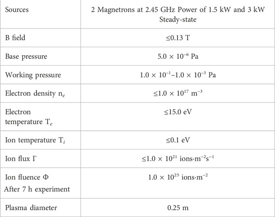
TABLE 1. Summary of the main features and plasma parameters of GyM linear device located at ISTP-Milan.
From the PWI point of view, the ion flux of GyM lies between the values of ion beam sputtering facilities [34] and those of LPDs based on arc plasma generators [2]. In particular, it is comparable to the hydrogen isotope CXN fluxes that will impinge on the main chamber of ITER [5] and the recessed elements of the DEMO first-wall [35]. Ion energies of a few hundred eV, which are the more typical for CXNs, can be obtained applying a proper negative bias voltage to the samples exposed to the plasma of GyM. By making the assumption that materials interactions with ions or neutrals having the same energy are substantially the same, one can conclude that GyM is suitable to (i) mimic PWI in ITER and DEMO, outside the divertor. It is important to stress that a full-day of operation of GyM (7 h) allows to reach ion fluences in the range of 1.0 × 1025 ions⋅m−2 which are roughly equivalent to the cumulative CXN fluence impinging on the main chamber of ITER after ∼50 discharges.GyM has been also used to: (ii) preliminarily characterize materials candidate for PFCs, like the investigation of the deuterium (D) retention of liquid tin (Sn), and (iii) obtain spectroscopic data, such as the ionization events per photon (S/XB) values of Sn and tungsten (W), (iv) develop new diagnostic methods, devoted for example to the absolute quantification of the ammonia produced in the plasma and (v) provide data for the benchmark of edge and PMI codes, like SOLPS-ITER [36] and ERO2.0 [37].
This paper is organized as follows. The layout of GyM, the diagnostics and the sample exposure systems are discussed in Section 2. The typical plasma parameters are presented in Section 3. The main PMI activities carried out so far are reported in Section 4. Finally, conclusions and the description of future machine upgrades are given in Section 5.
2 GyM linear plasma device
GyM consists of a stainless steel (SST) vacuum chamber, a pumping system, a gas injection system, 10 magnetic field coils, two magnetron sources at 2.45 GHz, a set of diagnostics and two manipulator systems for PMI experiments. Highly reproducible plasmas of different gas species can be obtained and steadily sustained by ECRH in the resonance layer at 87.5 mT. A photograph and the layout of GyM are shown in Figure 1. All the relevant components of GyM will be discussed in the following.
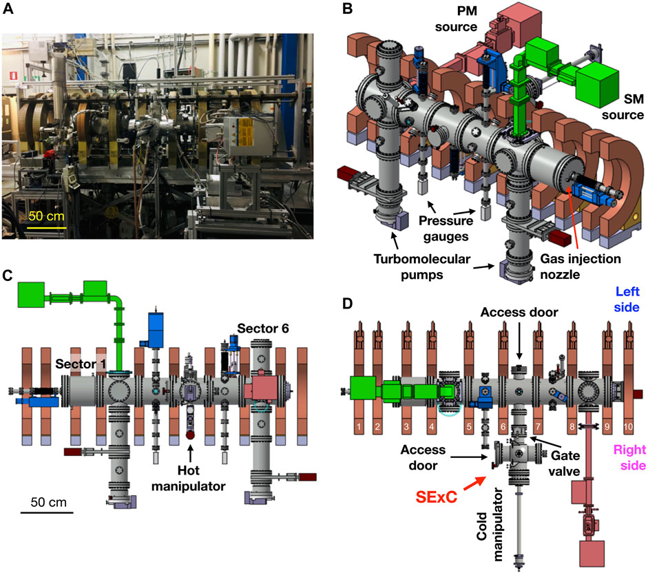
FIGURE 1. A photograph of GyM (A). Schematics of the device (B–D) with the main components in evidence. The lateral (C) and the top (D) views show the sector and coil numbering, respectively.
2.1 Vacuum vessel
The AISI 304L SST vacuum vessel of GyM is 2.11 m in length and 25 cm in diameter. It is electrically grounded. As one can see from Figure 1, the vessel is divided into six sectors and it is provided with a total of 29 ConFlat (CF) vacuum ports plus the 2 CF250 cylinder bases, for pumping, plasma heating and diagnostics. In the following, each port will be indicated by the number of the sector (see Figure 1C for sector numbering), followed by one or two letters among “U” (up), “D” (down), “L” (left) and “R” (right) according to the orientation of the port (please refer to Figure 1B for the left and right side of GyM). For example, port 3UR is the CF40 port in sector 3 at 45° between CF40 ports 3U and 3R. Two pumping lines are connected to the CF160 ports 2D and 6D. They both comprise a turbomolecular pump of 500 L/s backed by a rotary vane pump of 6.7 L/s. A base pressure of 5 × 10⁻⁶ Pa can be achieved after a day. Two identical double Bayard-Alpert/Pirani gauges are mounted on the CF40 ports 3D and 5D to monitor the vacuum status. They are installed at a distance greater than the outer diameter of the coils to protect them from the magnetic field (see Figures 1B, C). Gas injection takes place through a nozzle from the base of the vacuum vessel cylinder of sector 1 (see Figure 1B). The gas inlet system also includes three mass flow controllers. The full scale value is 50 sccm for two of them and 10 sccm for the third one (sccm stands for standard cubic centimeters per minute at standard ambient temperature and pressure). It is thus possible to puff up to three different gases in the vacuum vessel of GyM. The working pressure is usually in the range 10–1–10–3 Pa. Hydrogen (H), deuterium, helium (He), argon, nitrogen (N) plasmas have been considered so far. Moreover, nitrogen seeded deuterium (and hydrogen) plasmas (also with the addition of argon or helium) and helium plus ammonia mixed plasmas were used in the frame of the investigation of the ammonia production and decomposition in GyM (see Section 4; [20, 21, 25, 30]). A 3 mm thick SST liner (2 m in length and 20.6 cm in diameter) with a plasma-sprayed tungsten coating (50 μm in thickness and an average roughness of 10 μm) on the inner surface was provisionally installed in GyM to study the role of the wall material in the ammonia formation process. Two photographs of the interior of the vacuum vessel of GyM w/o and w/the liner are shown in Figure 2. The threaded bushings supporting the liner may be also seen in image 2a.
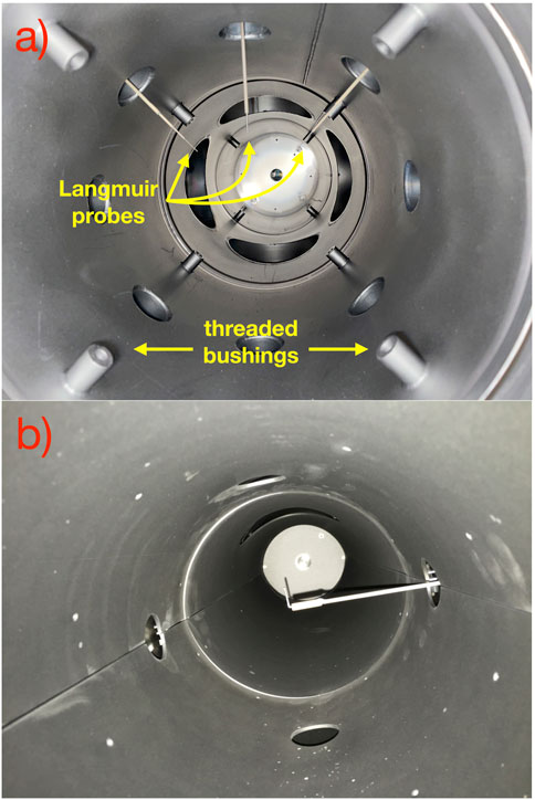
FIGURE 2. Photographs of the interior of the vacuum vessel of GyM w/o (A) and w/ (B) the W-coated liner. Pictures were taken from the CF100 quick access door of sector 4, pointing the camera to sector 1. Different Langmuir probes may be seen in the two figures. The threaded bushings supporting the liner are also indicated in (A).
2.2 Magnetic system
Ten identical oxygen-free copper coils surround the vacuum vessel of GyM (see Figure 1). They are connected in series. Each coil is made of two independent two turn (conductor size: 20.83 × 15.75 mm2), nine layer pancakes which are sandwiched together [38]. The two separate pancakes are wound in such a way that the axial current components due to the two turn-to-turn transitions cancel each other. Pancakes are water-cooled individually. Coil thickness and inner and outer diameters are 9.2 cm, 52.2 cm and 83.0 cm, respectively. The current in the solenoid is regulated by a 60 kW stabilized DC power supply (50 V–1200 A).
The position of the ten coils is freely adjustable along the mounting axis. The layout considered so far is shown in Figure 1. As regards the magnetic field configuration, an axial magnetic field is usually adopted. Optimization of the latter is possible changing the current flowing in the solenoid (Icoils), depending on the specific goals of each experiment. The magnetic field configuration with Icoils = 600 A is depicted in Figures 3A, B. Three different regions can be identified: a “high” field region between coils 1 and 4 (please refer to Figure 1D for the coil numbering) with B ∼95 mT, a “low” field region between coils 5 and 10 with B ∼80 mT and a “transition” region between coils 4 and 5 where the 87.5 mT fundamental harmonic ECR layer at 2.45 GHz can be observed. The latter is also the region in which the plasma is generated and sustained since the energy transfer from the electromagnetic radiation launched by the 2.45 GHz magnetron sources to the electrons is more efficient. The on-axis magnetic filed ripple in the low field region, −0.45 m ≤ Z ≤ 0.9 m, is
FIGURE 3. The two-dimensional distribution of
A double cusp magnetic field configuration was also designed and used to test the behavior of free liquid metal samples under plasma exposure (see Section 2.5; Section 4; [23, 24]). It can be obtained by current inversion in coils 7 and 8. The two-dimensional distribution of
2.3 Plasma sources
Plasma is sustained in continuous wave mode by means of electromagnetic waves at the electron cyclotron frequency of 2.45 GHz using two magnetrons. The first microwave (μ-W) system consists of an Alter SM1150 μ-W power supply driving an Alter TM030 magnetron head that delivers a μ-W power up to 3 kW (hereinafter “SM” source, see Figure 1B). The second system consists of an Alter PM740 μ-W power supply driving an Alter TM015 magnetron head that delivers up to 1.5 kW (hereinafter “PM” source). Each μ-W generator is protected by a circulator. A dual directional coupler monitors the forward and the backward μ-W power. A three-stub tuner allows the impedance of the μ-W line to be dynamically adjusted in order to match the variations in the impedance of the plasma-filled chamber. Rectangular WR-340 waveguides propagating the TE10 mode and a water-cooled rectangular quartz window complete the μ-W line. SM and PM sources are connected to ports 2U and 6R of GyM (see Figure 1), injecting the electromagnetic radiation perpendicularly to the magnetic field lines in O-mode polarization (μ-W wavevector
2.4 Diagnostic system
The plasma parameters are routinely measured by “homemade” single Langmuir probes (LPs) which typically consist of a SST wire partially covered by an alumina tube for electrical insulation. The series circuit of each Langmuir probe comprises a voltage signal generator, which is grounded, and an electrical resistor. The plasma electrically connects the probe to the grounded vacuum vessel creating a closed loop path in the circuit. The current-voltage (I-V) characteristics are obtained applying a triangle wave to the LPs. The triangle wave is customizable in terms of temporal duration, triangle frequency, minimum and maximum voltage level. The voltage across the resistor is measured and processed by the acquisition system. The resistor voltage signal from up to 11 LPs can be simultaneously measured at a sampling rate ≤250 kHz for each channel. Each amplification stage consists of an optical isolator, a 100 kHz low-pass filter, and two signal amplifiers, one upstream and one downstream of the filter, which can amplify the voltage signal by a factor of 0.1–1 and 1–10, respectively. A measurement usually lasts 1 s, at a triangle wave frequency of 50 Hz and in the voltage range between −74.1 V and 74.1 V, with a sampling rate of 150 kHz, during which 100 I-V characteristics are collected for each LP.
The plasma profiles of GyM can be obtained by installing the LPs on three CF40 linear shifts with remote-controlled stepper motors. The latter have a stroke of 15 cm. Figures 1B–D show typical locations of GyM linear shifts (the stepper motors are colored in blue). The first system is installed on the base of the vacuum vessel of sector 1 by a reducer CF250-CF40 flange (port “0”), to measure the axial profile of the plasma. The second and third linear shifts are installed on the CF40 ports 3U and 5U, to obtain the radial profiles of the plasma. The stroke of 15 cm allows, in principle, to measure the full radial profile of GyM plasma parameters, by properly choosing the length of the SST wire of the LP. The three single LPs have the naked part of the SST wire, or tip (i.e. outside the alumina tube), with the major axis normal to the machine axis (for this reason, the SST wire of LP 0 is bent at the end, at a right angle, as the one shown in Figure 2B). Typical length and diameter of the tips are 15 mm and 1.5 mm.
A high resolution (0.06 nm) spectrometer (Horiba Jobin Yvon) for optical emission spectroscopy (OES) is used to measure the radiation emitted by the plasma species and to identify the impurities, in the wavelength (λ) range of 300–900 nm. The spectrometer consists of a Czerny-Turner monochromator (iH550) coupled to a CCD camera (Synapse), thermoelectrically cooled to 200 K. The entrance optics comprises a focusing lens (f = 7.5 cm) and an optical fiber (5 m long and 600 μm in core diameter). The optical system, including a CF40 fused silica optical window, was absolutely calibrated on an optical table by a W halogen lamp and a plane Lambertian diffuser in the 300–900 nm λ-range.
The analysis of vacuum vessel neutral impurities (e.g. compounds of carbon, oxygen and nitrogen) is carried out with a Pfeiffer Vacuum Prisma quadrupole mass spectrometer (QMS) 200. Its mass range and resolution are 1–200 u and 1 u (at 129 u). The QMS has its own differentially pumped vacuum chamber which is connected to GyM via a 4 mm inner diameter hose. The nozzle of the hose’s flange is installed on port 2U and it is provided with a needle valve to separate GyM and QMS vacuum chambers. QMS vacuum system comprises a turbomolecular pump of 180 L/s backed by a diaphragm pump of 1.1 L/s. The pressure is measured by a Bayard-Alpert gauge. The background and working pressures of the QMS vacuum chamber are 10–6 Pa and
A Photron Ultima APX-RS fast visible camera can be used to image GyM plasmas and is capable of recording an image every 4 μs, at maximum frame rate, and has a 1024 × 1024 array of 17 × 17 μm complementary metal oxide semiconductor image sensors. The camera is equipped with a Nikon (NIKKOR, 50 mm, f/1.4 aperture) objective lens and with an image intensifier unit (Hamamatsu, model C10880-03) and a 1:1 relay lens. This imaging system is shared with Swiss Plasma Center—Ècole polytechnique fédérale de Lausanne [18].
In the frame of the study on ammonia production in GyM plasmas [20, 21, 25], a liquid nitrogen (LN2) trap was connected to the pumping system 6D, between the turbomolecular and rotary pumps, using a bypass valve. Since the ammonia condensation point (240 K) is above that of nitrogen (77 K), ammonia molecules contained in the exhaust gas of GyM stick on the LN2 trap surface. At the end of the plasma discharge, the LN2 trap can be removed from GyM and the ammonia quantification can be carried out by bubbling and liquid ion chromatography (LIC).
2.5 Manipulators for PMI investigation
PMI experiments are carried out in sector 4 by using one of the two stainless steel manipulators installed on GyM (see Figure 4). The surface of the samples points toward the ECR layer that is typically in sector 2. The first system is fitted to a rotatable CF160 flange of the sample exchange chamber (SExC), which is in turn connected to the CF100 flange 4R of GyM, see Figure 1D. A manual gate valve separates GyM vacuum vessel from SExC. The latter is also provided with turbomolecular pump of 230 L/s backed by a rotary vane pump of 4.4 L/s, a Pirani gauge and a CF160 quick access door for sample replacement. The manipulator consists of a magnetically-coupled linear drive, a SST carrier head and a molybdenum (Mo) sample holder (see Figure 4A). The linear drive allows to transfer the carrier head and the sample holder from SExC to the axis of GyM vacuum vessel. The carrier head comprises a water-cooled copper (Cu) block, an alumina sheet for electrical insulation and another Cu plate, all embedded in a SST structure. The sample holder is fixed by two Mo screws on top of the Cu plate and it can accommodate up to four 1 × 1 cm2 samples. Since the specimens are actively cooled by the Cu block, this manipulator will be labeled as “cold” in the following. Mo was preferred to SST for the manufacturing of the sample holder (and the screws) due to its lower erosion yield, Y (at the ion energies and with the plasma species here considered), thus reducing the sputtering and the possible deposition of particles on the surface of the exposed samples. A grounded tantalum (Ta) shield is also placed around the target holder to prevent the erosion of the carrier head (YTa is even lower than YMo). Thanks to the alumina sheet, a negative bias voltage down to −400 V can be applied to the samples in order to tailor the energy of the incoming ions. The temperature of the specimens is measured by a Inconel sheathed type K thermocouple (ø = 1.0 mm), with the hot junction located behind the centre of the Mo mask. Since the cold manipulator is installed on a rotatable flange of the SExC, it is possible to change the angle θ among the sample surface and the magnetic field lines of the axial configuration, between two consecutive exposures (Figures 3A, B). However, almost all the experiments with this manipulator were carried out at θ = 90° (“normal” exposures) in order to maximize the ion flux to the sample holder.
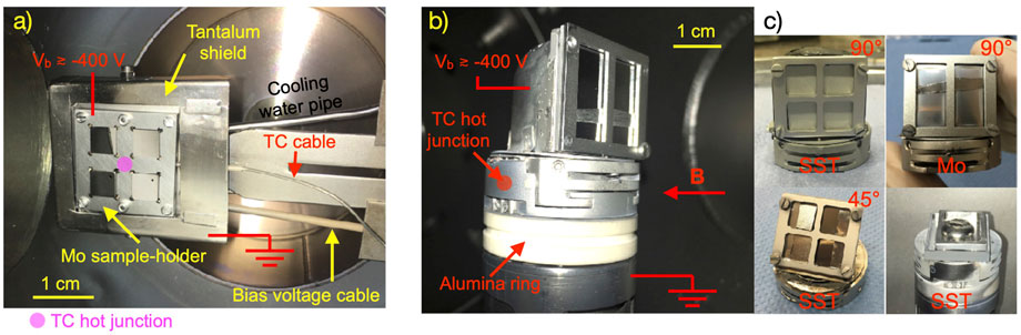
FIGURE 4. Photographs of: the cold manipulator from the CF160 quick access door of SExC (A) and the hot manipulator from the CF100 quick access door of sector 4 (B). Different sample carrier heads of the hot manipulator (C). Top and bottom left: the carrier heads for normal and 45° exposures with the SST holder which can accommodate up to four 1 × 1 cm2 samples. Top-right: the carrier head for normal exposures with the Mo holder which can accommodate up to two 1 × 2 cm2 samples. Bottom-right: SST horizontal carrier head with a SST tray, overall size of 20.4 × 18.4 mm2, and a liquid tin droplet in the centre.
With the manipulator retracted in the SExC and the gate valve between GyM vacuum vessel and SExC closed, it is possible to vent the SExC and remove the holder from the quick access window. Once the new samples are loaded in the target holder and the latter secured on the carrier head, the chamber can be vacuumed. The pressure reaches ∼5.0 × 10⁻⁴ Pa (∼2.0 × 10⁻⁴ Pa) after few hours (after pumping overnight) and then the gate valve can be opened. GyM background pressure increases from
The second manipulator is installed on the CF40 flange 4D (see Figure 1C) and can be moved along the radial direction by means of a handwheel and a bellow. The R-range is of 15 cm. When the bellow is fully stretched, the target holder is completely extracted from the cylindrical vacuum vessel of GyM. When the bellow is fully compressed, the target holder lies on GyM axis. The manipulator consists of a SST cylinder which terminates with a SST carrier head and a sample holder (Figure 4B). The latter two are electrically insulated from the ground potential at the cylinder by an alumina ring. A negative bias voltage down to −400 V can thus be applied to the samples. A water-cooled heat lamp is also embedded in the manipulator body and can heat the rear side of the samples up to ∼1000 K to study the role of material temperature during PMI experiments. As such, this manipulator will be labeled as “hot” hereinafter. The temperature of the carrier head is measured by a Inconel sheathed type K thermocouple (ø = 0.5 mm) with the hot junction located near the target holder. The samples can be kept at a constant temperature by means of a proportional-integrative-derivative, PID, controller which regulates the power to the heat lamp using the temperature read by the thermocouple or by the pyrometer, see below, as the process variable. Different SST carrier heads and sample holders are available for different purposes. They are depicted in Figure 4C. The two upper panels show images of the carrier head for normal exposures. The lower left panel shows the manipulator head for exposures at θ = 45°. Keep in mind that, even though this angle is far away from 90°, the ions impinging on the negatively biased sample surface still arrive perpendicular to it due to the relatively low value of GyM magnetic field [39]. This carrier head was sometimes preferred to the normal exposure head since it allows to have access to the sample surface by a diagnostic installed on the CF40 flange 4U. This was done at the price of a reduced ion flux to the target holder by a factor cos θ ≃0.71. In particular, an Impac Infratherm 247/5 pyrometer can be used to directly monitor the surface temperature of the samples, which is a critical parameter to properly interpret the outcomes of PMI experiments [22, 30]. Alternatively, the OES system can be connected to port 4U to study the erosion of the samples, as described in [23, 24].
Two different sample holders can be fixed with four (SST or Mo) screws to the normal and 45° carrier heads. The first one is a SST holder which can accommodate up to four 1 × 1 cm2 samples (upper and lower left panels of Figure 4C). The second one is a Mo holder which can accommodate up to two 1 × 2 cm2 samples (upper right panel of Figure 4C).
A SST horizontal carrier head with a SST tray (overall size of 20.4 × 18.4 mm2) is also available. It was used, in combination with the double-cusp magnetic configuration (Figures 3C, D), to expose free liquid tin samples to the plasma of GyM [23, 24] (liquid metals like tin and lithium have been proposed as possible alternatives to solid PFCs, see Section 4), as shown in the lower right panel of Figure 4C. The horizontal carrier can arrange only one sample at a time.
The main drawback of this manipulator is that venting of GyM is necessary to change the samples at the end of the exposure. The carrier head is removed by using the CF100 quick access door installed on port 4L (see Figures 1B, D). The whole procedure of venting the vessel, replacing the samples and vacuuming the chamber to a background pressure of
3 Plasma parameters of GyM
As mentioned in Section 2.4, the plasma profiles of GyM are measured by three single LPs installed on CF40 linear shifts with remote-controlled stepper motors. The axial and radial distribution profiles of electron density, temperature, plasma potential (Vpl) and ion flux obtained for an Ar plasma, with SM source power of 1200 W, a pressure of 8.0 × 10⁻³ Pa and the axial magnetic configuration with Icoils = 600 A (Figures 3A, B), are shown in Figure 5. The layout of the linear shifts is the same as that described in Section 2.4 and it is pictured in Figure 5A again, for convenience of the reader. Figure 5B shows the axial plasma profiles measured with the LP installed on port 0 between 22 cm and 36 cm from the base of the vacuum vessel of sector 1. Figure 5C shows the radial profiles measured by the two LPs installed on port 3U (in red) and 5U (in blue), between 0 cm and 11 cm from the axis of the machine. The major axis of the two probes is ∼50 cm and 115 cm far away from the ECR layer. From Figure 3B, Figure 5A, it is possible to notice that the three LPs allow to get insights into the plasma properties of both the high and low field regions (“HF” and “LF” regions in the following) on the left and right of the ECR layer, respectively. The length and diameter of the tips were 15 mm and 1.5 mm, for all the probes. Three measurements were done for each axial/radial position, to make statistics. Each acquisition lasted 1 s, at a triangle wave frequency of 50 Hz and in the voltage range between −66.7 V and 74.1 V, with a sampling rate of 150 kHz. The modified version of the perimeter sheath expansion method described in [33] was used to interpret the I-V characteristics. Each scatter point of Figures 5B, C is the average of the plasma parameter values obtained from the three repeated measurements, and the shadowed region represents the associated standard deviation.
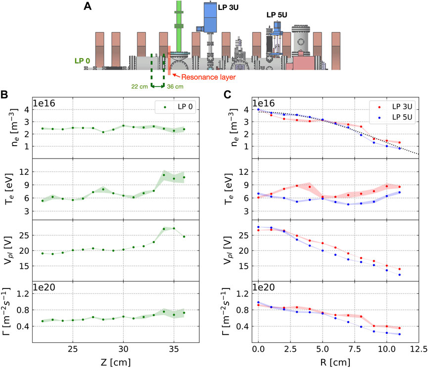
FIGURE 5. Layout of the linear shifts (A). The first system was installed on port 0 to measure the axial profile of the plasma. The second and the third systems were installed on ports 3U and 5U, to obtain the radial profiles of the plasma. Three cylindrical single SST LPs were installed on the shifts, with the major axis normal to the machine axis. The length and diameter of the tips were 15 mm and 1.5 mm. Electron density, ne, temperature, Te, plasma potential, Vpl, and ion flux, Γ, along the axial, Z (B), and radial, R (C), coordinate, measured for an Ar plasma, with SM source power of 1200 W, a pressure of 8.0 × 10⁻³ Pa and the axial magnetic configuration with Icoils = 600 (A). Each scatter point is the average of the plasma parameter values obtained from three repeated measurements, and the shadowed region represents the associated standard deviation. The dotted black line in the ne plot of figure (C) is the parabolic fit of ne,5U.
The axial plasma profile of electron density at the high field side remains at about 2.5 × 10¹⁶ m−3 all over the range investigated (Figure 5B). The electron temperature stays between 6 eV and 8 eV from 22 cm to 32 cm and then increases to ∼11 eV approaching the ECR layer where the absorption of the electromagnetic wave by the plasma is more efficient. The behavior of Vpl and Γ is similar to that of Te since Vpl ∝ Te and
At the low field side, LPs 3U and 5U measured the same electron density of 4.0 × 10¹⁶ m−3 on the axis (R = 0 cm), despite being ∼65 cm away from each other. It is also clear that ne,LF > ne,HF. We infer that this is due to: (i) the higher connection length for electrons moving from the ECR layer toward the base of the cylinder of sector 6 with respect to those directed toward the base of sector 1 and (ii) the weak magnetic mirror effect which could in principle better confine the electrons in the LF region (see Figures 3A, B). They both lead to a higher electron dwell time inside the LF region and in turn to a higher electron-impact ionization rate of Ar atoms. The ne radial profiles from LPs 3U and 5U are similar: ne,3U is flatter between 2 cm and 8 cm, while ne,5U is well-fitted with a parabolic arch. Te radial profiles are approximately constant with Te,3U ≳Te,5U, since LP 3U is closer to the “hotter” ECR region. From this and Γ ∝ ne [40], it follows that the ion flux behaves like the electron density for the two probes and Γe,3U ≳Γe,5U. Both Vpl profiles have a parabolic shape and Vpl,3U ≳Vpl,5U due to Vpl ∝ Te.
On the whole, the radial profiles of Figure 5C show that the plasma properties are very similar moving along the axis inside the LF region. In particular, the electron population is approximately isothermal along a given flux tube. Considering the terminology of [40], GyM operates in the so-called sheath-limited regime, where the features of the plasma are mainly defined by the heat transmission properties of the electrostatic sheath adjacent to the two bases of the vacuum vessel.
During PWI experiments in GyM, samples are exposed to the plasma in sector 4, about halfway between LPs 3U and 5U (∼30 cm far from them). The centre of the sample holder is usually placed on the axis of the vacuum vessel when the axial magnetic configuration is considered (Figures 3A, B). In this case, the farthest point of the samples is at a distance of R ∼2 cm from the axis (see Figures 4A, B). From Figure 5C, it is possible to conclude that the samples arranged on the target holder are exposed to the same plasma conditions, especially the ion flux, which is one of the most important figures of merit of LPDs for PWI, is nearly constant in the range 0 cm ≤ R ≤ 5 cm.
4 Plasma-material interaction studies on GyM
The linear device GyM was originally thought to investigate basic plasma physics [16–18], as mentioned in Section 1. Since 2014, it has been mainly used to study the issue of PMI for nuclear fusion applications [19–30].
The main aspects of the PMI issue investigated with GyM are: (i) the erosion dynamics of reduced activation ferritic martensitic (RAFM) steels, like Eurofer-97, candidate for the recessed elements of the first wall of DEMO [22], (ii) the effects of plasma on laboratory-prepared nanostructured tungsten coatings used to mimic tokamak W-based re-deposits [19, 29, 30], (iii) the adhesion of micron-sized tungsten dust particles deposited on W substrates [26, 27], (iv) the deuterium retention of divertor-relevant liquid tin [24], and (v) the erosion of solid bulk Sn and W samples for the determination of the spectroscopic parameter S/XB [23, 24]. As mentioned earlier, another well-established activity is (vi) the study of ammonia formation in nitrogen-seeded deuterium plasmas [20, 21, 25]. Some of these activities and the main related results will be briefly described in the following Subsections.
4.1 RAFM steels deuterium plasma erosion
As written in Section 1, GyM ion flux of 1020–1021 ions⋅m−2s−1 is suitable to study hydrogen isotope CXN flux impinging on the recessed elements of the DEMO first-wall. Among the possible materials (tungsten, for example) candidate for these components, bare RAFM steels are a valuable economical and technological option. They are iron (Fe)-based alloys containing small amounts of high-Z elements, such as W. RAFM steel samples, and Fe-W coatings - model systems of RAFM steels - were exposed to the deuterium plasma of GyM at different fluences (Φ = 5.0 × 1024–2.5 × 1025 ions⋅m−2), temperatures (Tsample = 600 K, 990 K) and ion energies (Eion = 120–320 eV) to study their erosion behavior. Fe-W coatings were considered first [22]. The attention was then shifted to the more complex and most prominent Eurofer-97. Recently, the erosion of HiperFer and CroFer [41] has been also addressed, in order to extend the investigation to other steels interesting for nuclear fusion applications.
It was found that the sputtering yield of all these materials significantly changes with plasma fluence and sample temperature. Being multi-component coating/alloys, the composition of their surface and, in turn, their erosion dynamics are indeed expected to change due to: the preferential sputtering of elements with high Y (in particular, since YFe > YW, iron erodes fast, leading to a W-rich surface difficult to be sputtered) [35] and temperature-dependent processes, like thermal diffusion and Gibbs segregation of the different components [22]. Considering Eurofer-97, it was found that the peculiar dependence of Y with Φ and Tsample is subtly related to the morphological evolution of the samples. Scanning electron microscopy (SEM) and atomic force microscopy (AFM) showed the formation of a rough micro-structured layer on the surface of all the exposed samples, whose morphology changed both with Φ and Tsample. Moreover, energy-dispersive X-ray spectroscopy pointed out that surface nanostructures are enriched with tungsten. It thus follows that W surface concentration and distribution also depend on Φ and Tsample, finally explaining the interlink between the morphology and sputtering yield of Eurofer-97.
These findings are consistent with the literature of RAFM steels exposed to low energy (a few hundred eV) deuterium ions of an ion beam in the SIESTA device [42], the ECR plasma in the experiment PlaQ [43] and high-flux linear plasma devices [44–46]. In particular, Eurofer-97 samples exposed in GyM developed a morphology very similar to the fence/corral-like one shown in [45], although the fluence was much higher (1026–1027 ions⋅m−2) and the ion energy was lower (∼40 eV), there. All the details about these experiments and the interpretation of the results are going to be published elsewhere.
4.2 Plasma effects on nanostructured tungsten films having fusion-relevant features
GyM was also used to simulate the interaction between hydrogen isotope CXNs and W-based deposits that will build-up on the main chamber of ITER [19, 20, 29, 30]. PWI will lead to the erosion of W divertor tiles of ITER. Sputtered particles could be promptly re-deposited in the vicinity of the erosion source or could migrate in the plasma edge and eventually deposit in another region of the first-wall, together with fuel species, extrinsically seeded impurities (like nitrogen, injected in the plasma to reduce the power and particle flux to the divertor) and material from other PFCs and structural elements [47–51]. As the post-mortem analyses of tiles of tokamaks operative to date have demonstrated, the re/co-deposited layers in ITER will feature different morphology, structure, composition and thickness compared to the pristine PFCs. This could lead also to different erosion dynamics, retention, mechanical and thermophysical properties. A deep knowledge of the behavior of re/co-deposits during plasma exposure is therefore strongly required to properly control PWI when ITER will start working.
To this end, laboratory-prepared nanostructured W coatings mimicking tokamak W-based re-deposits were prepared at NanoLab of Politecnico di Milano and exposed, together with polycrystalline bulk W as reference, to the deuterium plasma of GyM at a fluence of 7.0 × 1024 ions⋅m−2, changing the energy of the impinging ions in the range Eion = 20–320 eV [29]. W coatings (∼400 nm in thickness) with different morphology (compact columnar, compact amorphous-like and porous) and structure (mean crystallite dimension, MCS, from 15 nm to
Starting with blistering, the dominant process of blister formation may be different for bulk W PFCs and W re/co-deposits. Due to the very low tungsten solubility for hydrogen, the deuterium concentration in the implantation zone of bulk W during plasma exposure may greatly exceed the solubility limit (supersaturation in the near-surface layer) and deuterium may start to precipitate at nucleation points, like defects (dislocations, grain boundaries and vacancies). Cavity growth can then take place [52]. Blistering of re/co-deposits may be also caused by deuterium accumulation at the interface between them and the PFCs underneath. It may be followed by deposit delamination and production of dust particles which may terminate the plasma discharge [55]. Blisters found on the W coatings exposed in GyM are really likely to be related to the deuterium build-up at the film-substrate interface, as pointed out by SEM analysis. The other two more relevant findings are the following. First, the morphology of the W coatings plays a major role in suppressing blister formation. Porous W films did not blister after exposure, contrary to compact coatings, probably because of their open morphology, which led to the desorption of deuterium from the surface. Second, blistering in the W films can be suppressed increasing the average roughness of the substrate. Blisters were found on every compact coatings, except for the one deposited on top of the rough polycrystalline bulk W with Ra = 500 nm.
Considering nanostructure formation, a strong correlation between their shape and grain orientation of bulk W exposed to a high flux (1024 ions⋅m−2s−1) deuterium plasma beam, for a fluence of 7.0 × 1026 ions⋅m−2 and ion energy of ∼38 eV, was reported in [53, 54]. Three typical structures were observed. Jagged (triangular) and spongy-like nanostructures were found on grains with surface normal (SN) near ⟨111⟩ and ⟨100⟩, respectively. Ripple (lamellar) nanostructures were seen on grains with other SN directions. Nanostructure formation was explained by surface reconstruction (i.e., displacement of metal atoms on top surface) occurring to relieve the stress field induced by the high transient D content during plasma exposure. Moreover, it was related to a high concentration of crystal defects in the samples. The same kinds of nanostructures were also found by SEM on the surface of reference bulk W samples exposed to the D plasma of GyM at Eion ≳100 eV. In comparison with [53, 54], the higher Eion may have enhanced the induced stress field on the surface of the samples leading to nanostructure formation even for an ion flux and fluence two orders of magnitude lower. The effect on bulk W of the interaction with (high flux and energy of a few eV) divertor-relevant plasmas or (low flux and energy of a few hundred eV) CXNs at the nanoscale is therefore very similar.
The exposure of W coatings with different morphology and structure to the D plasma of GyM allowed to study the role of mean crystallite and grain sizes in the process of nanostructure formation. It was found that an ion energy threshold (Eion,thold) value, below which no nanostructures could be detected, exists and increases reducing the dimension of the crystalline domains. On the one hand, the compact columnar W films, having the highest MCS of 15 nm, showed the same Eion,thold of bulk W but developed only ripple structures as a consequence of their oriented crystallographic growth along the ⟨110⟩ direction [56]. On the other hand, the porous W coatings having the lowest MCS of 1 nm, did not show any nanostructure even at 300 eV.
The strong influence of the features at the micrometer and nanoscale of the W films on their behavior upon plasma exposure was also evident seeding the deuterium plasma of GyM with nitrogen (D + N plasma in the following) [20, 30]. The role of the temperature of the samples was also addressed. In [30], compact W coatings (∼300 nm in thickness) with different morphology (columnar and amorphous-like) and structure (with MCS of 20 nm and
The study of the properties of laboratory-prepared nanostructured W coatings is still continuing by considering the modifications induced to the films by the helium plasma of GyM. The main purpose is here to provide data for the benchmark of plasma-material interaction models (see Section 4.5).
4.3 Deuterium retention of divertor-relevant liquid tin
GyM was helpful to qualify liquid tin as a plasma-facing material by studying, for the first time, its deuterium retention with different ion beam analysis (IBA) techniques [24] and with the thermal desorption spectroscopy (TDS). Liquid metals, as Sn, have been proposed as a possible alternative to solid PFCs thanks to their high heat dissipation capabilities by convection, evaporative cooling and vapor shielding, their regenerative properties and resilience to erosion and neutron damage [60, 61]. Free liquid Sn samples were exposed to the deuterium plasma of GyM by means of: the double cusp magnetic field configuration (see Section 2.2) combined with the hot manipulator (see Section 2.5) placing the horizontal target holder 6 cm below the axis of the vacuum chamber (see the lower right panel of Figure 4C). In this way, the diverted magnetic field lines transported the plasma ions toward the surface of the exposed samples. The surface temperature of the latter was monitored by the pyrometer which was installed on the port 4U. Each sample was placed on a SST support (to avoid the adhesion of re-solidified tin to the target holder at the end of the experiment) and actively heated up by the lamp of the hot manipulator at ∼600 K (Sn melting point is 505 K) before the plasma exposure. The temperature was then kept constant by means of the PID controller, using the pyrometer temperature as the process variable. Liquid tin specimens were exposed to the deuterium plasma of GyM at a fluence of Φ = 1.0 × 1024 ions⋅m−2. The holder was at floating potential. At the end of the experiments, the samples were let re-solidify in vacuum and stored in dry air at room temperature. D2 retention in the near-surface region was investigated ex-situ by: elastic coil detection analysis, nuclear reaction analysis and Rutherford backscattering spectrometry. Besides, bulk retention was evaluated by TDS. IBA techniques agreed that the amount of deuterium in the samples was very low,
4.4 Ammonia formation in nitrogen-seeded deuterium plasmas
GyM was exploited to study the production of ammonia in D + N plasmas [20, 21, 25]. Extrinsic impurity seeding of the plasma of full-metal fusion reactors, like ITER, will be necessary to avoid localized overheating in the divertor by converting a major part of the power flux into radiation [64]. Nitrogen is one of the candidates as a seeding element since it efficiently cools the edge plasma and, at the same time, increases the plasma confinement [65]. The main drawback of nitrogen is the related ammonia (ND3) formation. As far as ITER is concerned, the production of large quantities of ND3 has consequences for several aspects of the plant operation in terms of gas reprocessing and duty cycle [66].
In this framework, GyM was used as a test bed to study the mechanisms underlying ND3 formation in a nitrogen seeded deuterium plasma and develop a method for ammonia absolute quantification. The D + N plasma of GyM was diagnosed by: a Langmuir probe installed on port 4U, with the SST cylindrical electrode on GyM axis, to evaluate ne and Te, the OES mounted on port 3U, thus with the line of sight perpendicular to the plasma column, to investigate the plasma composition, and the differentially pumped QMS connected to GyM through the nozzle of port 2U, to study the evolution of the neutral chemical species. Absolute quantification of ND3 involved the following steps: (i) collection of ammonia during D + N plasma experiments by means of the LN2 trap connected to the pumping system of sector 6 (see Section 2.4), (ii) ex-situ regeneration of the LN2 trap to room temperature, (iii) bubbling of the exhausted gas into distilled water at 278 K by Ar flow, and (iv) analysis of the solution using liquid ion chromatography [20, 21, 25].
Ammonia formation was studied as a function of: plasma discharge duration, electron temperature (from ∼3 eV–6 eV, by changing the power of the microwave SM source), total pressure (pt = 3.0 × 10⁻²–6.0 × 10⁻² Pa) [20, 21]. LIC clearly showed that ND3 production increased with Te and decreased with the increasing total pressure. The results of these experiments can be explained considering the following scheme for ND3 formation which was corroborated by OES observations [21]. First, ND radicals were produced in the plasma volume due to the chain reaction:
The ND radicals could then reach the vessel by diffusion. Ammonia formation occurred through surface recombination reactions among the adsorbed ND radicals and deuterium atoms or molecules, with the wall acting as a catalyst. Finally, ND3 was released into the plasma.
The higher production of ammonia at the higher electron temperatures is related to the increase with Te of the rate coefficients for the electron impact reactions (1) and (3), which play a key role in the formation of ND radicals in the plasma volume. This specific dependence of ammonia production on Te can also explain why LIC detected a decreasing amount of ND3 at the higher D + N plasma total pressures. Indeed, the Langmuir probe data showed a decrease of Te by increasing pt. A higher ND3 concentration lowering pt agrees with the experimental and modelling results reported in [67] relating to a H2 + 10% N2 plasma (pt = 0.8–8 Pa) generated in a hollow cathode dc reactor.
The injection of an extra noble gas impurity, like argon and helium, into the D + N plasma of GyM was then investigated as a possible approach to limit the ammonia formation [21, 25]. The main finding is a strong decrease of ND3 production in D + N + He plasmas. This was ascribed to the chemico-physical processes occurred on the vessel surface, as suggested by the results of the OES and LIC analyses. In particular, it was inferred that the He particles impinging on the wall reduced the number of sites available for the reactants (i.e., ND radicals, D atoms and D2 molecules) of the catalysis reaction responsible for the ammonia formation in GyM.
Recently, possible isotopic and wall material effects were also addressed. The former was studied by comparing the quantity of ammonia produced during nitrogen seeded deuterium and hydrogen plasmas. The latter was investigated by inserting the SST liner with the plasma-sprayed W coating on the inner surface into the vacuum vessel of GyM (see Section 2.1). The interpretation of the results is underway and will be published elsewhere.
Moreover, the cleaning of GyM vacuum vessel by Ar-H or Ar-D plasmas has been routinely carried out at the end of each campaign on ammonia formation in GyM to remove the adsorbed N-based compounds from the wall thus preventing the possible pollution of the plasma during the following experiments.
4.5 Modelling of GyM plasma and PWI experiments
In support of the experimental program of GyM, modelling activities in the frame of a collaboration between NanoLab of Politecnico di Milano and ISTP-Milan, have been developed in the recent years [28, 68, 69]. First, the tokamak plasma edge SOLPS-ITER code [36] has been successfully applied to the argon plasma of GyM and benchmarked against the radial profiles of the electron density and temperature from Langmuir probe [28]. Second, the local impurity transport and PMI Monte-Carlo code ERO2.0 [37] has been used to simulate the experimental outcomes from the exposure of W coatings to the helium plasma of GyM. These modelling activities have the perspective of coupling SOLPS-ITER with ERO2.0 in order to interpret PMI experiments in a comprehensive fashion.
5 Conclusion and perspectives
This contribution described the linear plasma device GyM of ISTP-Milan and its applications in the field of plasma-wall interaction in magnetic confinement nuclear fusion. Most of the PWI activities have been carried out and will continue within the framework of the EUROfusion Consortium.
In GyM, highly reproducible large-volume uniform plasmas can be obtained and steadily sustained by electron cyclotron resonance heating using two magnetrons at 2.45 GHz and a set of ten magnetic field coils which provides the ECR zone at 87.5 mT. The working pressure is usually in the range 10–1–10–3 Pa. Plasmas of GyM have an electron and ion temperature of Te ≤ 15 eV and Ti ∼0.1 eV. The plasma density is in the range of 1015–1017 m−3 and the ion flux Γ ≤ 5 × 10²⁰ ions⋅m−2s−1. Main plasma diagnostics of GyM comprise several Langmuir probes (up to 11), an optical emission spectrometer, a mass spectrometer and a fast camera system equipped with an image intensifier unit. PWI experiments are carried out with two different sample exposure systems. Both are biasable at a maximum voltage of −400 V to tune the energy of the incoming ions. One of them is also equipped with a heating lamp and can reach and sustain a temperature of 990 K for several hours, thus allowing to study the role of sample temperature during the plasma-material interaction. Considering the topic of PWI, GyM is mainly suitable to: (i) study the effect of hydrogen isotope CXN fluxes impinging on the main chamber of ITER and the recessed elements of the DEMO first-wall, (ii) preliminarily characterize and (iii) obtain spectroscopic values of materials candidate for PFCs, (iv) develop new diagnostic methods and (v) provide data for the benchmark of edge and PMI codes. The main aspects of the PMI issue investigated with GyM are: the erosion dynamics of RAFM steels, candidate for the recessed elements of the first wall of DEMO, the effects of plasma on nanostructured W coatings used to mimic tokamak re-deposits, the adhesion of dust particles, the deuterium retention of liquid tin, and the erosion of solid bulk Sn and W samples for the determination of the spectroscopic parameter S/XB. Another well-established activity is the study of ammonia formation in nitrogen-seeded deuterium plasmas. In support of the experimental program of GyM, modelling activities in the frame of a collaboration between NanoLab of Politecnico di Milano and ISTP-Milan, have been developed in the recent years using SOLPS-ITER code and ERO2.0. The upgrades of GyM which are planned for the next future aim to make it more attractive from the perspective of PWI divertor studies. A Gycom gyrotron at 28 GHz, 15 kW cw, together with a 1 T Varian magnet, which are both already available at ISTP-Milan, will be installed on GyM in 2023 with the purpose of increasing the maximum achievable plasma density, and thus the ion flux. The cut-off electron density for 28 GHz is ∼9.7 × 10¹⁸ m−3. The vacuum vessel placed inside the 1 T magnet bore will be connected to the base of GyM of sector 1 by a vacuum fitting. The electromagnetic waves will be injected on the axis of GyM. The design of the transmission line is currently ongoing. In view of the installation of the gyrotron source, present sample exposure systems could not withstand the power load from plasma and stray radiation. A new system is therefore mandatory and the project phase has just begun. Unlike the current systems, the new manipulator and sample holder will be installed on the base of sector six and will move along the axis of GyM. This allows to change the distance between the sample surface and: (i) the line of sight of the OES, usually perpendicular to the plasma column, to evaluate the ionization mean free path of the sputtered atoms and (ii) the surface of the sensor plate of a quartz crystal microbalance, which will be soon integrated into the layout of GyM, to study the angular dependence of the sputtering yield. One of the most important features of the new sample exposure system will be the capability to heat the samples to the operational temperature of ITER divertor PFCs of 1500 K.
Author contributions
AU wrote the first draft of the manuscript. All authors contributed to the development of the linear device GyM and to the different activities described in the paper. All authors also contributed to manuscript revision.
Funding
This work has been carried out within the framework of the EUROfusion Consortium, funded by the European Union via the Euratom Research and Training Programme (Grant Agreement No 101052200—EUROfusion). Views and opinions expressed are however those of the author(s) only and do not necessarily reflect those of the European Union or the European Commission. Neither the European Union nor the European Commission can be held responsible for them. The activity has been performed under EUROfusion work-packages plasma-facing components (WP-PFC, FP8) and plasma-wall interaction and exhaust (WP-PWIE, FP9).
Acknowledgments
The authors would like to thank Prof. Matteo Passoni, David Dellasega, Elena Tonello and Gabriele Alberti of Politecnico di Milano for the useful and fruitful collaboration. The authors would also like to thank Saul Garavaglia and Enzo Lazzaro for their help in the design and construction of GyM.
Conflict of interest
The authors declare that the research was conducted in the absence of any commercial or financial relationships that could be construed as a potential conflict of interest.
Publisher’s note
All claims expressed in this article are solely those of the authors and do not necessarily represent those of their affiliated organizations, or those of the publisher, the editors and the reviewers. Any product that may be evaluated in this article, or claim that may be made by its manufacturer, is not guaranteed or endorsed by the publisher.
References
1. Kreter A. Reactor-relevant plasma-material interaction studies in linear plasma devices. Fusion Sci Tech (2011) 59:51–6. doi:10.13182/FST59-1T-51
2. Linsmeier C, Unterberg B, Coenen JW, Doerner RP, Greuner H, Kreter A, et al. Material testing facilities and programs for plasma-facing component testing. Nucl Fusion (2017) 57:092012. doi:10.1088/1741-4326/aa4feb
3. Brezinsek S, Coenen JW, Schwarz-Selinger T, Schmid K, Kirschner A, Hakola A, et al. Plasma–wall interaction studies within the EUROfusion consortium: Progress on plasma-facing components development and qualification. Nucl Fusion (2017) 57:116041. doi:10.1088/1741-4326/aa796e
4. Merola M, Escourbiac F, Raffray R, Chappuis P, Hirai T, Martin A. Overview and status of ITER internal components. Fusion Eng Des (2014) 89:890–5. Proceedings of the 11th International Symposium on Fusion Nuclear Technology-11 (ISFNT-11) Barcelona, Spain, 15-20, 2013. doi:10.1016/j.fusengdes.2014.01.055
5. Federici G, Brooks JN, Coster DP, Janeschitz G, Kukuskhin A, Loarte A, et al. Assessment of erosion and tritium codeposition in ITER-FEAT. J Nucl Mater (2001) 290:260–5. 14th Int. Conf. on Plasma-Surface Interactions in Controlled Fusion Devices. doi:10.1016/S0022-3115(00)00627-9
6. Linsmeier C, Rieth M, Aktaa J, Chikada T, Hoffmann A, Hoffmann J, et al. Development of advanced high heat flux and plasma-facing materials. Nucl Fusion (2017) 57:092007. doi:10.1088/1741-4326/aa6f71
7. De Temmerman G, van den Berg MA, Scholten J, Lof A, van der Meiden HJ, van Eck HJN, et al. High heat flux capabilities of the Magnum-PSI linear plasma device. Fusion Eng Des (2013) 88:483–7. Proceedings of the 27th Symposium On Fusion Technology (SOFT-27); Liège, Belgium September 24-28, 2012. doi:10.1016/j.fusengdes.2013.05.047
8. Goebel DM, Campbell G, Conn RW Plasma surface interaction experimental facility (PISCES) for materials and edge physics studies. J Nucl Mater (1984): 277–282. doi:10.1016/0022-3115(84)90135-1
9. Goebel DM, Hirooka Y, Conn RW, Leung WK, Campbell GA, Bohdansky J, et al. Erosion and redeposition experiments in the pisces facility. J Nucl Mater (1987) 145–147: 61–70. doi:10.1016/0022-3115(87)90310-2
10. Hirooka Y, Conn RW, Sketchley T, Leung WK, Doerner R, Elverum J, et al. A new plasma-surface interactions research facility: PISCES-B and first materials erosion experiments on boronized graphite (UCLA/PPG–1253). (1989). United States
11. Baldwin MJ, Doerner RP, Nishijima D, Patino M, Simmonds MJ, Tynan G, et al. Plasma-Material-Interaction Research Using PISCES Linear Plasma Devices. Fusion Sci Technol (2019) 75:664–673. doi:10.1080/15361055.2019.1646608
12. Tynan GR, Bailey AD, Campbell GA, Charatan R, de Chambrier A, Gibson G, et al. Characterization of an azimuthally symmetric helicon wave high density plasma source. J Vac Sci Technol A (1997) 15:2885–2892. doi:10.1116/1.580844
13. Thakur SC, Simmonds MJ, Caneses JF, Chang F, Hollmann EM, Doerner RP, et al. PISCES-RF: a liquid-cooled high-power steady-state helicon plasma device. Plasma Sources Sci Technol (2021) 30:055014. doi:10.1088/1361-6595/abef19
14. Kreter A, Brandt C, Huber A, Kraus S, Möller S, Reinhart M, et al. Linear plasma device PSI-2 for plasma-material interaction studies. Fusion Sci Tech (2015) 68:8–14. doi:10.13182/FST14-906
15. Scholten J, Zeijlmans van Emmichoven PA, van Eck HJN, Smeets PHM, De Temmerman GC, Brons S, et al. Operational status of the Magnum-PSI linear plasma device. Fusion Eng Des (2013) 88:1785–8. Proceedings of the 27th Symposium On Fusion Technology (SOFT-27); Liège, Belgium, September 24-28, 2012. doi:10.1016/j.fusengdes.2013.05.063
16. Granucci G, Ricci D, Alocci S, Baiocchi B, Bin W, Bruschi A, et al. The new linear plasma device GyM at IFP-CNR. 36th EPS Conf Plasma Phys (2009) 33 E2:1107–10. EPS 2009 - Europhysics Conference Abstracts.
17. Ricci D, Iraji D, Cremona A, Furno I, Garavaglia S, Granucci G, et al. Experimental characterization of instabilities in the linear machine GyM. 39th EPS Conf Plasma Phys (2012) 3:1506–9. 2012, EPS 2012 and the 16th International Congress on Plasma Physics.
18. Iraji D, Ricci D, Granucci G, Garavaglia S, Furno I, Cremona A, et al. Imaging of turbulent structures and tomographic reconstruction of GyM plasma emissivity. Fusion Sci Tech (2012) 62:428–35. doi:10.13182/FST12-A15342
19. Vassallo E, Caniello R, Angella G, Dellasega D, Granucci G, Mellera V, et al. Retention of nanocrystalline WNx layers exposed to high-fluence deuterium plasmas. J Nucl Mater (2015) 466:621–6. doi:10.1016/j.jnucmat.2015.09.006
20. Laguardia L, Caniello R, Cremona A, Dellasega D, Dell’Era F, Ghezzi F, et al. Ammonia formation and W coatings interaction with deuterium/nitrogen plasmas in the linear device GyM. J Nucl Mater (2015) 463:680–3. Proceedings of the 21st International Conference on Plasma Surface Interactions 2014, 21st PSI. doi:10.1016/j.jnucmat.2014.12.087
21. Laguardia L, Caniello R, Cremona A, Gatto G, Gervasini G, Ghezzi F, et al. Influence of He and Ar injection on ammonia production in N2/D2 plasma in the medium flux GyM device. Nucl Mater Energ (2017) 12:261–6. Proceedings of the 22nd International Conference on Plasma Surface Interactions 2016, 22nd PSI. doi:10.1016/j.nme.2017.05.009
22. Caniello R, Uccello A, Ghezzi F, Minelli D, Bogdanović Radović I, Siketić Z, et al. Erosion yield and W surface enrichment of Fe-W model system exposed to low flux deuterium plasma in the linear device GyM. Nucl Mater Energ (2017) 10:9–16. doi:10.1016/j.nme.2017.01.014
23. Cremona A, Uccello A, Causa F, Caniello R, De Iuliis S, Dondè R, et al. Experimental determination of S/XB values of Sn I emission lines in GyM device. 44th EPS Conf Plasma Phys (2017) EPS:2017.
24. Cremona A, Vassallo E, Alves E, Causa F, De Iuliis S, Dondè R, et al. Deuterium retention and erosion in liquid Sn samples exposed to D2 and Ar plasmas in GyM device. Nucl Mater Energ (2018) 17:253–8. doi:10.1016/j.nme.2018.11.010
25. Laguardia L, Behringer K, Cremona A, Gatto G, Gervasini G, Ghezzi F, et al. Impact of He admixture on the ammonia formation in N2 seeded D2 plasmas in the GyM facility. 45th EPS Conf Plasma Phys EPS (2018) 2018:649–52.
26. Tolias P, De Angeli M, Riva G, Ratynskaia S, Daminelli G, Laguardia L, et al. The adhesion of tungsten dust on plasma-exposed tungsten surfaces. Nucl Mater Energ (2019) 18:18–22. doi:10.1016/j.nme.2018.12.002
27. Tolias P, De Angeli M, Ratynskaia S, Riva G, Bassani P, Ripamonti D, et al. Diffusion bonding effects on the adhesion of tungsten dust on tungsten surfaces. Nucl Mater Energ (2020) 24:100765. doi:10.1016/j.nme.2020.100765
28. Sala M, Tonello E, Uccello A, Bonnin X, Ricci D, Dellasega D, et al. Simulations of argon plasmas in the linear plasma device GyM with the SOLPS-ITER code. Plasma Phys Controlled Fusion (2020) 62:055005. doi:10.1088/1361-6587/ab7c4f
29. Sala M, Uccello A, Dellasega D, Pedroni M, Vassallo E, Passoni M. Exposures of bulk W and nanostructured W coatings to medium flux D plasmas. Nucl Mater Energ (2020) 24:100779. doi:10.1016/j.nme.2020.100779
30. Uccello A, Ghezzi F, Laguardia L, Caniello R, Dellasega D, dell’Era F, et al. Effects of a nitrogen seeded plasma on nanostructured tungsten films having fusion-relevant features. Nucl Mater Energ (2020) 25:100808. doi:10.1016/j.nme.2020.100808
31. Castro G, Mascali D, Gammino S, Torrisi G, Romano FP, Celona L, et al. Overdense plasma generation in a compact ion source. Plasma Sourc Sci Tech (2017) 26:055019. doi:10.1088/1361-6595/aa61c4
32. Geller R. Electron cyclotron resonance ion sources and ECR plasmas. Bristol, United Kingdom: IOP Publishing (1996).
33. Causa F, Gervasini G, Uccello A, Granucci G, Ricci D, Rispoli N. Obtaining the unperturbed plasma potential in low-density, low-temperature plasmas. Plasma Sourc Sci Tech (2021) 30:045008. doi:10.1088/1361-6595/abef1b
34. Sugiyama K, Schmid K, Jacob W. Sputtering of iron, chromium and tungsten by energetic deuterium ion bombardment. Nucl Mater Energy (2016) 8:1–7.
35. Roth J, Sugiyama K, Alimov V, Höschen T, Baldwin M, Doerner R. EUROFER as wall material: Reduced sputtering yields due to W surface enrichment. J Nucl Mater (2014) 454:1–6. doi:10.1016/j.jnucmat.2014.07.042
36. Wiesen S., Reiter D., Kotov V., Baelmans M., Dekeyser W., Kukushkin A. S., et al. The new SOLPS-ITER code package. J Nucl Materials (2015) 463:480–484. doi:10.1016/j.jnucmat.2014.10.012
37. Eksaeva A, Borodin D, Romazanov J, Kirschner A, Kreter A, Eichler M, et al. Surface roughness effect on Mo physical sputtering and re-deposition in the linear plasma device PSI-2 predicted by ERO2.0. Nucl Mater Energ (2019) 19:13–8. doi:10.1016/j.nme.2019.02.006
39. Devaux S, Manfredi G. Magnetized plasma–wall transition—Consequences for wall sputtering and erosion. Plasma Phys Controlled Fusion (2008) 50:025009. doi:10.1088/0741-3335/50/2/025009
40. Stangeby PC. The plasma boundary of magnetic fusion devices. In: Series in plasma physics and fluid dynamics. Taylor & Francis (2000).
41. Möller S, Kuhn B, Rayaprolu R, Heuer S, Rasinski M, Kreter A. HiperFer, a reduced activation ferritic steel tested for nuclear fusion applications. Nucl Mater Energ (2018) 17:9–14. doi:10.1016/j.nme.2018.06.010
42. Arredondo R, Balden M, Mutzke A, von Toussaint U, Elgeti S, Höschen T, et al. Impact of surface enrichment and morphology on sputtering of EUROFER by deuterium. Nucl Mater Energ (2020) 23:100749. doi:10.1016/j.nme.2020.100749
43. Ogorodnikova O, Zhou Z, Sugiyama K, Balden M, Gasparyan Y, Efimov V. Surface modification and deuterium retention in reduced-activation steels under low-energy deuterium plasma exposure. Part I: Undamaged steels. Nucl Fusion (2017) 57:036010. doi:10.1088/1741-4326/57/3/036010
44. Alimov V, Hatano Y, Yoshida N, Watanabe H, Oyaidzu M, Tokitani M, et al. Surface modification and sputtering erosion of reduced activation ferritic martensitic steel F82H exposed to low-energy, high flux deuterium plasma. Nucl Mater Energ (2016) 7:25–32. doi:10.1016/j.nme.2016.01.001
45. Balden M, Elgeti S, Zibrov M, Bystrov K, Morgan T. Effect of the surface temperature on surface morphology, deuterium retention and erosion of EUROFER steel exposed to low-energy, high-flux deuterium plasma. Nucl Mater Energ (2017) 12:289–96. doi:10.1016/j.nme.2017.01.001
46. Alimov V, Hatano Y, Yoshida N, Bobyr N, Oyaidzu M, Tokitani M, et al. Surface morphology of F82H steel exposed to low-energy D plasma at elevated temperatures. J Nucl Mater (2018) 510:366–72. doi:10.1016/j.jnucmat.2018.08.037
47. Rasinski M, Fortuna-Zalesna E, Mayer M, Neu R, Plocinski T, Lewandowska M, et al. High resolution scanning transmission electron microscopy (HR STEM) analysis of re-deposited layer on ASDEX Upgrade tile. Fusion Eng Des (2011) 86:1753–6. Proceedings of the 26th Symposium of Fusion Technology (SOFT-26). doi:10.1016/j.fusengdes.2011.02.085
48. Litnovsky A, Matveeva M, Herrmann A, Rohde V, Mayer M, Sugiyama K, et al. First studies of ITER-diagnostic mirrors in a tokamak with an all-metal interior: Results of the first mirror test in ASDEX upgrade. Nucl Fusion (2013) 53:073033. doi:10.1088/0029-5515/53/7/073033
49. Baron-Wiechec A, Fortuna-Zaleśna E, Grzonka J, Rubel M, Widdowson A, Ayres C, et al. First dust study in JET with the ITER-like wall: Sampling, analysis and classification. Nucl Fusion (2015) 55:113033. doi:10.1088/0029-5515/55/11/113033
50. Fortuna-Zalesna E, Andrzejczuk M, Ciupinski L, Rozniatowski K, Sugiyama K, Mayer M, et al. Post mortem analysis of a tungsten coated tile from the outer divertor strike point region of ASDEX upgrade. Nucl Mater Energ (2016) 9:128–31. doi:10.1016/j.nme.2016.10.011
51. Fortuna-Zaleśna E, Grzonka J, Rubel M, Garcia-Carrasco A, Widdowson A, Baron-Wiechec A, et al. Studies of dust from JET with the ITER-Like Wall: Composition and internal structure. Nucl Mater Energ (2017) 12:582–7. Proceedings of the 22nd International Conference on Plasma Surface Interactions 2016, 22nd PSI. doi:10.1016/j.nme.2016.11.027
52. ’t Hoen MHJ, Balden M, Manhard A, Mayer M, Elgeti S, Kleyn AW, et al. Surface morphology and deuterium retention of tungsten after low- and high-flux deuterium plasma exposure. Nucl Fusion (2014) 54:083014. doi:10.1088/0029-5515/54/8/083014
53. Xu HY, Zhang YB, Yuan Y, Fu BQ, Godfrey A, De Temmerman G, et al. Observations of orientation dependence of surface morphology in tungsten implanted by low energy and high flux D plasma. J Nucl Mater (2013) 443:452–7. doi:10.1016/j.jnucmat.2013.07.062
54. Xu HY, Luo GN, Schut H, Yuan Y, Fu BQ, Godfrey A, et al. Enhanced modification of tungsten surface by nanostructure formation during high flux deuterium plasma exposure. J Nucl Mater (2014) 447:22–7. doi:10.1016/j.jnucmat.2013.12.010
55. Shoji M, Kasahara H, Tokitani M, Seki T, Saito K, Kamio S, et al. Studies of dust transport in long pulse plasma discharges in the large helical device. Nucl Fusion (2015) 55:053014. doi:10.1088/0029-5515/55/5/053014
56. Dellasega D, Merlo G, Conti C, Bottani CE, Passoni M. Nanostructured and amorphous-like tungsten films grown by pulsed laser deposition. J Appl Phys (2012) 112:084328. doi:10.1063/1.4761842
57. Ogorodnikova OV, Sugiyama K, Markin A, Gasparyan Y, Efimov V, Manhard A, et al. Effect of nitrogen seeding into deuterium plasma on deuterium retention in tungsten. Physica Scripta (2011) T145:014034. doi:10.1088/0031-8949/2011/T145/014034
58. Gao L, Jacob W, Meisl G, Schwarz-Selinger T, Höschen T, von Toussaint U, et al. Interaction of deuterium plasma with sputter-deposited tungsten nitride films. Nucl Fusion (2016) 56:016004. doi:10.1088/0029-5515/56/1/016004
59. Nemanič V, Zajec B, Dellasega D, Passoni M. Hydrogen permeation through disordered nanostructured tungsten films. J Nucl Mater (2012) 429:92–8. doi:10.1016/j.jnucmat.2012.05.031
60. Coenen JW, De Temmerman G, Federici G, Philipps V, Sergienko G, Strohmayer G, et al. Liquid metals as alternative solution for the power exhaust of future fusion devices: Status and perspective. Physica Scripta (2014) T159:014037. doi:10.1088/0031-8949/2014/T159/014037
61. Tabarés FL. Present status of liquid metal research for a fusion reactor. Plasma Phys Controlled Fusion (2015) 58:014014. doi:10.1088/0741-3335/58/1/014014
62. Ou W, Al RS, Vernimmen JWM, Brons S, Rindt P, Morgan TW. Deuterium retention in Sn-filled samples exposed to fusion-relevant flux plasmas. Nucl Fusion (2020) 60:026008. doi:10.1088/1741-4326/ab5cd4
63. Manhard A, Schwarz-Selinger T, Balden M, Dürbeck T, Maier H, Neu R. Deuterium retention in solid and liquid tin after low-temperature plasma exposure. Nucl Fusion (2020) 60:106007. doi:10.1088/1741-4326/aba801
64. Kallenbach A, Bernert M, Dux R, Casali L, Eich T, Giannone L, et al. Impurity seeding for tokamak power exhaust: From present devices via ITER to DEMO. Plasma Phys Controlled Fusion (2013) 55:124041. doi:10.1088/0741-3335/55/12/124041
65. Kallenbach A, Balden M, Dux R, Eich T, Giroud C, Huber A, et al. Plasma surface interactions in impurity seeded plasmas. J Nucl Mater (2011) 415:S19–26. – S26. Proceedings of the 19th International Conference on Plasma-Surface Interactions in Controlled Fusion. doi:10.1016/j.jnucmat.2010.11.105
66. Touchard S, Mougenot J, Rond C, Hassouni K, Bonnin X. Ammonx: A kinetic ammonia production scheme for eirene implementation. Nucl Mater Energ (2019) 18:12–7. doi:10.1016/j.nme.2018.11.020
67. Carrasco E, Jiménez-Redondo M, Tanarro I, Herrero VJ. Neutral and ion chemistry in low pressure dc plasmas of H2/N2 mixtures: Routes for the efficient production of NH3 and \mathrm{NH}_{4}^+. Phys Chem Chem Phys (2011) 13:19561–72. doi:10.1039/c1cp22284h
68. Tonello E, Formenti A, Alberti G, Uccello A, Passoni M. A point plasma model for linear plasma devices based on SOLPS-ITER equations: Application to helium plasma. Nucl Fusion (2021) 61:066036. doi:10.1088/1741-4326/abfbb3
Keywords: nuclear fusion, tokamak, linear plasma device, GyM, plasma-facing components, plasma-material interaction
Citation: Uccello A, Bin W, Bruschi A, Causa F, Cremona A, De Angeli M, Farina D, Gatto G, Gervasini G, Ghezzi F, Gittini G, Granucci G, Grosso G, Laguardia L, Lontano M, Mellera V, Minelli D, Nardone A, Pedroni M, Ripamonti F, Rispoli N, Vassallo E and Ricci D (2023) Linear plasma device GyM for plasma-material interaction studies. Front. Phys. 11:1108175. doi: 10.3389/fphy.2023.1108175
Received: 25 November 2022; Accepted: 13 January 2023;
Published: 01 February 2023.
Edited by:
Matteo Passoni, Politecnico di Milano, ItalyReviewed by:
Dan M. Goebel, NASA Jet Propulsion Laboratory (JPL), United StatesGuillaume Lombardi, Université Sorbonne Paris Nord, France
Copyright © 2023 Uccello, Bin, Bruschi, Causa, Cremona, De Angeli, Farina, Gatto, Gervasini, Ghezzi, Gittini, Granucci, Grosso, Laguardia, Lontano, Mellera, Minelli, Nardone, Pedroni, Ripamonti, Rispoli, Vassallo and Ricci. This is an open-access article distributed under the terms of the Creative Commons Attribution License (CC BY). The use, distribution or reproduction in other forums is permitted, provided the original author(s) and the copyright owner(s) are credited and that the original publication in this journal is cited, in accordance with accepted academic practice. No use, distribution or reproduction is permitted which does not comply with these terms.
*Correspondence: Andrea Uccello, YW5kcmVhLnVjY2VsbG9AaXN0cC5jbnIuaXQ=