 Meng-Jun Xie
 La-Qun Liu
- School of Electronic Science and Engineering, University of Electronic Science and Technology of China, Chengdu, China
In most of the simulations of the extraction region of negative hydrogen ion sources, the single-aperture simulation is often adopted by researchers to study the plasma phenomenon due to its small simulation domain and short calculation time. However, due to the complex three-dimensional magnetic field structure in the extraction region of the negative hydrogen ion source, the single aperture often does not meet the periodicity. In this paper, the complex three-dimensional magnetic field topology is established. The magnetic field includes the magnetic filter field and the magnetic deflection field. The influence of the plasma sheath is taken into account. The electron extraction process in the multi-aperture structure of the extraction region of a negative hydrogen ion source is numerically calculated using the PIC method. Besides, the magnetic field structure is optimized. Ultimately, the electron beam uniformity near the plasma grid is improved effectively, which has certain guiding significance for engineering application.
Introduction
Ion source, as the starting device of neutral beam injection (NBI) system, has become the research target of many scholars in recent years. Among ion sources, especially radio-frequency (RF) negative hydrogen ion source, it was listed as the reference scheme for plasma generation in the International Thermonuclear Experimental Reactor (ITER) Project in 2007 due to its advantages of simple structure, almost maintenance-free and low cost [1]. In the research of RF negative hydrogen ion source devices, the Max-Planck-Institute für Plasma Physik (IPP) in Germany, as an advanced research institution, has developed BATMAN, BATMAN upgrade, MANITU, ELISE and RADI experimental devices over the years [2–4]. These devices are characterized by different ion source size, pulse length, extraction area and RF power [1, 5–8]. RF ion sources can be divided into driver region, expansion region and extraction region. Generally, hydrogen or deuterium gas is used as the working gas into the driver region. The induction coupling electromagnetic field generated by RF power causes the electron and neutral gas to collide, ionize and produce plasma. The plasma then diffuses into the vacuum expansion region and is cooled by the magnetic filter field at the source side. Finally, the beam is accelerated by the three plates in the extraction region, namely, the plasma grid (PG), the extraction grid (EG) and the grounded grid (GG). Since electrons are also electronegative and will be extracted together with the beam, EG is often embedded with deflection magnets, and the resulting magnetic deflection field will dump the co-extracted electrons onto EG, reducing the co-extracted electron current and making the ratio of the co-extracted electron current density to negative ion current density less than 1, which is also one of the requirements of ITER [9].
The quality of the beam is determined by the plasma generated in the driver region and the design of the extraction region. Experimental attempts are often made to optimize the geometry of apertures in PG to improve the quality of the beam. For example, in the experiments of two different extraction systems (aperture diameters of 8 and 14 mm respectively) of the BATMAN device, preliminary results show that there is no major correlation between the extraction current density and aperture diameter [1]. However, the relevant experiments of the 14 mm aperture diameter extraction system are still hampered by the weak power load processing ability, and no clear conclusions can be drawn [10]. To determine the influence of various factors on beam quality by experiment, the technical difficulties need to be overcome. Therefore, it is necessary to make reasonable usage of simulation to understand the factors of beam quality.
Many relevant simulations of the extraction region mainly focus on the extraction of single aperture [11, 12], because the geometric structure of apertures is periodic, and secondly, due to the limitation of Debye length (generally on the order of 20
The three-dimensional Particle-In-Cell (PIC) simulation method is adopted based on the self-developed CHIPIC code [15–18] in this paper. A complex three-dimensional magnetic field topology is established, which includes a magnetic filter field and a magnetic deflection field. The electron extraction process in multi-aperture structure of negative hydrogen ion source is numerically calculated based on the recent research [15], and the magnetic field structure is optimized to improve the electron beam uniformity near PG plate.
Simulation setup
As shown in Figure 1, the Particle-In-Cell/Monte Carlo Collision (PIC/MCC) method [19] and the Scalar Magnetic Potential finite-difference Method (SMPM) [15, 16, 20] are adopted on CHIPIC code. The particle motion, force, charge, and current density updates adopt the PIC method, while the particle collision part adopts the MCC method. Since the emitted electron in the following is determined based on the emitted electron distribution after the collision, this paper does not consider the influence of collision factor, and focuses on tracking the distribution and motion trajectory of electrons after the spatiotemporal iteration of simulation.

FIGURE 1. The process cycle diagram of PIC/MCC and SMPM methods on CHIPIC code.
Figure 2A shows the schematic view of negative hydrogen ion source. The aperture structure in the extraction region of negative hydrogen ion source is established by referring to the LAG extraction system [10] of BATMAN testbed of German IPP. The extraction domain is composed of bias plate (BP), PG and EG, and the simulation domain is cut off from behind the EG to reduce calculation time. Figure 2B is the distribution diagram of the aperture tunnel on the EG, showing the longitudinal section of the EG plate in the Y-Z direction; Figure 2C is the schematic diagram of the simulation domain in the X-Z direction. The Port structure in Figures 2B, C acts as the feed-in voltage and a boundary condition to truncate the simulation domain respectively. There are 126 apertures on the PG and EG plates. The inner radius of the aperture is 3 mm, the outer radius is 4 mm, and the extraction area is about 0.0063 m2. The movable magnetic boxes are placed 9 cm in front of the PG. Each box contains the “2X4” permanent magnet. The formed long-range weak magnetic filter field can reduce the electron density near the PG. The EG is embedded with permanent magnetic rods with alternating magnetization, forming a short-range strong magnetic deflection field in a direction perpendicular to the magnetic filter field [21]. In this paper, SMPM method is adopted to calculate the three-dimensional static magnetic field generated by permanent magnets. The bias current is measured on the PG [22], and the co-extracted electron current is measured on the EG [23]. The BP and PG are located 1 cm apart axially. The BP is connected to the chamber and at the same potential [24]. The feed-in voltage parameters are shown in Table 1. Since the time step is on the order of 1 picosecond, the calculation amount of 3D model is huge. In this paper, non-uniform grid is used to reduce the number of grids in the simulation domain. The maximum grid step is 4 mm and the minimum one is 1 mm. More simulation parameter settings are shown in Table 2.
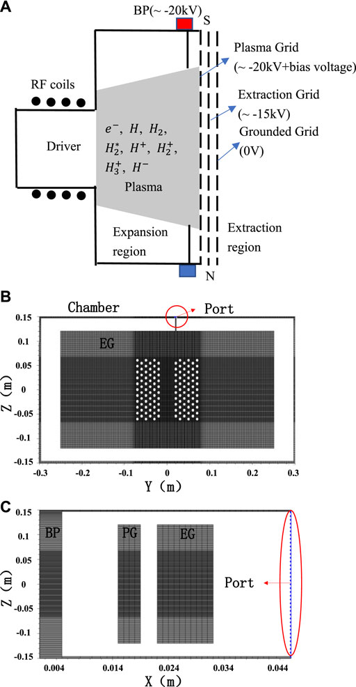
FIGURE 2. (A) Schematic view of negative hydrogen ion source; (B). The distribution diagram of the aperture tunnels on the EG; (C). The schematic diagram of the simulation domain in the X-Z direction.
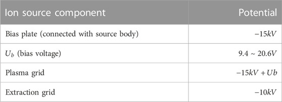
TABLE 1. Potential parameters of source components [25].
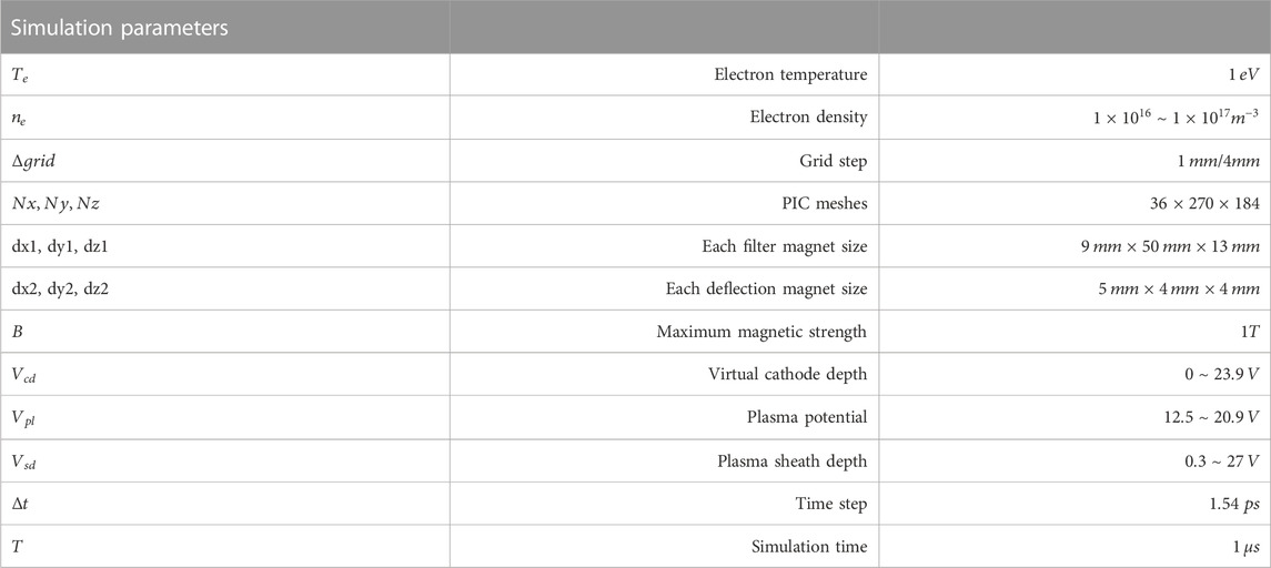
TABLE 2. Simulation parameters used in the code during beam extraction process.
The electron velocity conforms to the three-dimensional Maxwell distribution function, i.e., the electron velocity obeys Eq. 1, where,
References [26, 27] show the different plasma potentials measured at different positions when electrons move from the expansion region to the extraction region, which indicates that the electron density is obviously non-uniform. The main reason for this phenomenon is the magnetic drift of electrons caused by the magnetic filter field in the expansion region. This phenomenon has also been seen and explained on the basis of our recent work [15]. Therefore, the distribution of electrons at the BP also presents a non-uniform phenomenon. Based on the previous calculation [15], the electron current density distribution on the BP is re-assigned as the initial setting for electron beam emission in the extraction region in this paper. The current density distribution of electron beam emission on the BP is shown in Figure 3. The emission area is
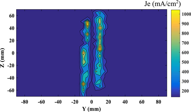
FIGURE 3. The current density distribution of electron beam emission on the BP.
Due to the density of the electron beam up to
where,
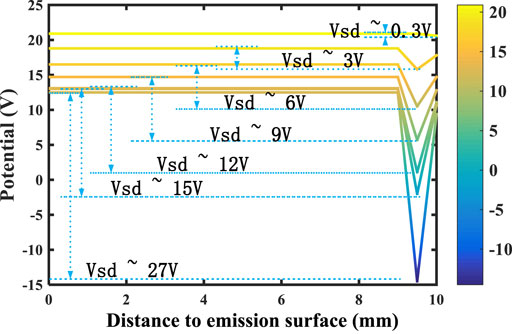
FIGURE 4. The potential distribution from the emission surface (Distance to emission surface = 0 mm) to the PG (Distance to emission surface = 10 mm).
Numerical calculation results
Comparison of magnetic filter field and magnetic deflected field with experimental data and FEM
The placement schematics of the filter magnets and the deflection magnets are shown in Figures 5A, B, respectively. The filter magnets are magnetized along the +Z direction at a distance of 9 cm from the PG. The deflection magnets are embedded in the EG, and the magnetization direction of magnets is alternately magnetized along the X direction, which is perpendicular to the magnetic filter field. The magnetic field components distribution of
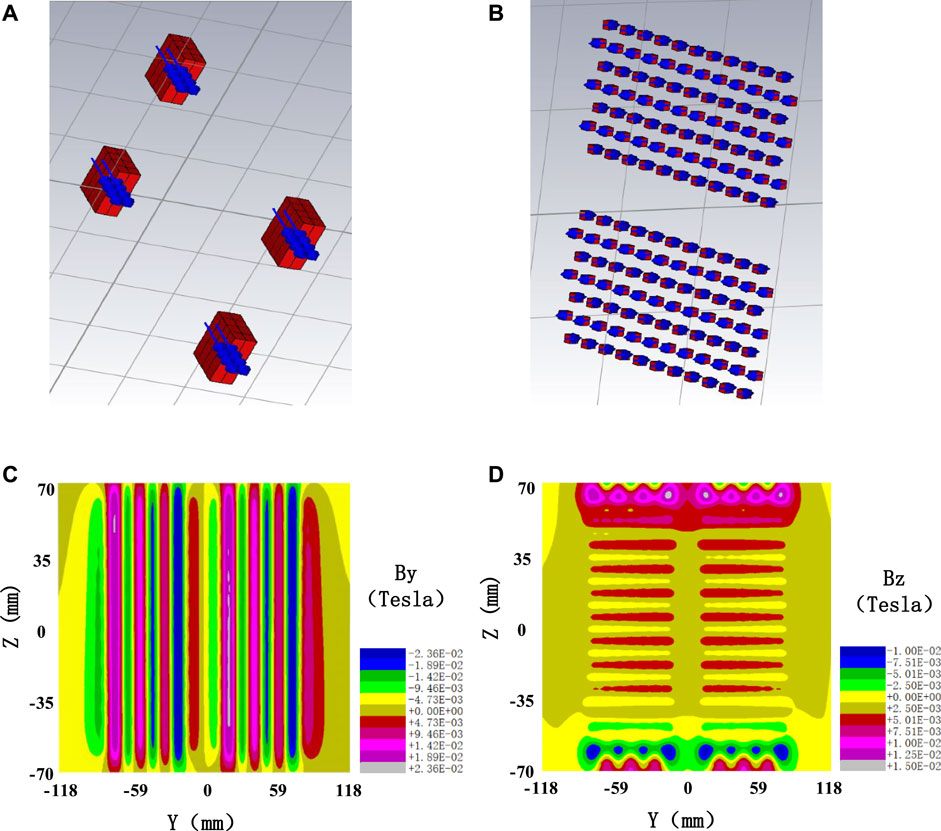
FIGURE 5. (A) The placement schematics of the filter magnets; (B). The placement schematics of the deflection magnets; (C). The magnetic field component distribution of
Figure 6 shows the distribution of the long-range weak magnetic filter field and the short-range strong magnetic deflection field near the PG along the X-axis, and the observation lines go across a beam axis of the PG aperture [21]. SMPM is used to calculate the 3D magnetic filter and deflection fields. The sign of the magnetic deflection field depends on the individual magnet row. As shown in Figure 6, the yellow dotted area represents the BP, which is also the region where electrons start. The magnetic field in the area before the BP (X < 0 mm) is set to zero. The solid green line area represents the PG, and the thickness of both BP and PG is 4 mm. The red and blue solid lines represent the calculated magnetic filter field
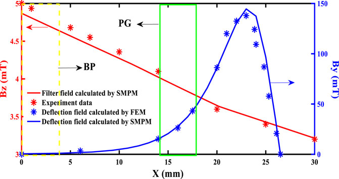
FIGURE 6. The distribution of the long-range weak magnetic filter field and the short-range strong magnetic deflection field near the PG along the X-axis.
Effect of magnetic field on the spatial distribution of electrons
Figures 7A, B shows the spatial distribution of electrons in the X-Z direction and X-Y direction (
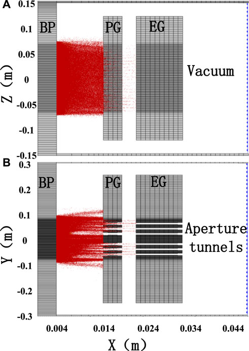
FIGURE 7. (A) The spatial distribution of electrons in the X-Z direction; (B).The spatial distribution of electrons in the X-Y direction.
Comparison of key simulation data and experiments
Figure 8 shows the diagram of electron energy probability distribution function (EEPF) as a function of electron energy in front of PG at 0.6 Pa. It can be seen that the simulated electron temperature is maintained at 1 eV by calculating the slope of the curve. It is in good agreement with 0.9 eV experimental data [34] at 0.5 Pa. It can be verified that the electron temperature is not affected by grid heating and energy distribution of electrons basically agrees with experimental data.
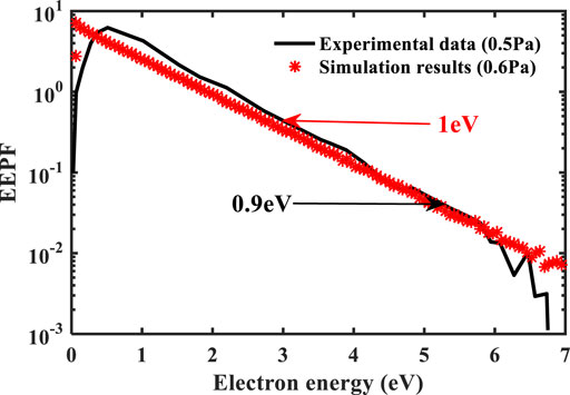
FIGURE 8. Diagram of EEPF as a function of electron energy in front of PG.
Figure 9 shows the plasma potential
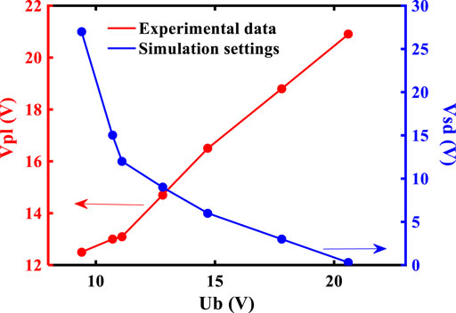
FIGURE 9. The plasma potential
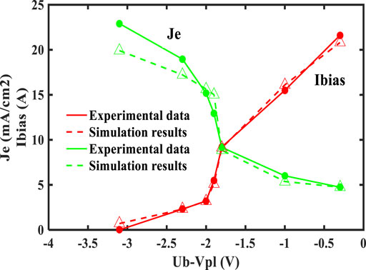
FIGURE 10. The diagram of the bias current
Optimization of the magnetic field
Due to electron drift effect, non-uniform plasma potential is formed on the PG metal surface. The virtual cathode depth near the PG surface is also non-uniform, so that the non-homogeneous negative ion flux generated on the PG surface enters the plasma or is extracted by the PG apertures [35]. As a result, the non-uniform distribution of electrons in the extraction region leads to the non-uniformity of the extracted
where
The optimization of magnetic field is similar to the setting of multicusp magnetic field [27]. Four longilineal magnets are selected, and the size of them is
FIGURE 11. The placement diagram of the added magnets.
Figures 12A, B show the spatial distribution diagram of electrons in the X-Y direction before and after magnetic field optimization and C, D show the electron density distribution in the Y direction 1 mm before PG before and after optimization. Compared Figures 12A, B, the optimized spatial distribution of electrons is more symmetrical in the Y direction. Compared Figures 12C, D, it can be seen that the symmetry of electron density before optimization is poor, while the optimized electron density distribution is almost symmetric with respect to the center point of the Y-axis. Besides, the electron vertical asymmetry coefficient
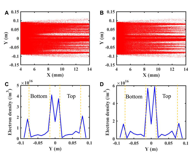
FIGURE 12. (A). The spatial distribution diagram of electrons in the X-Y direction before the magnetic field optimization; (B). The spatial distribution diagram of electrons in the X-Y direction after the magnetic field optimization; (C). The electron density distribution in the Y direction near 1 mm of the PG before the optimization; (D). The electron density distribution in the Y direction near 1 mm of the PG after the optimization.
The simulation results show that this magnet placement can effectively reduce
Conclusion
The total magnetic field near the apertures has a complex 3D structure due to the superposition of the magnetic filter and deflection fields. In this paper, based on the multi-aperture structure of three-dimensional RF negative hydrogen ion source BATMAN extraction region, the complex magnetic field topology is calculated by SMPM, and the plasma sheath depth is reasonably considered. The correlation between the plasma sheath potential drop and the bias current and the co-extracted electron current density is tellingly reflected. The dynamic characteristics of electrons in the multi-aperture extraction region are successfully simulated under non-periodic magnetic structure. In this paper, the magnetic field of the extraction region is optimized, and the electron uniformity is effectively improved, which has certain guiding significance for engineering application. However, the optimization of the magnetic field is not yet optimal, and the optimal solution remains to be further studied.
Data availability statement
The raw data supporting the conclusion of this article will be made available by the authors, without undue reservation.
Author contributions
Conceptualization, M-JX and H-HW; methodology, D-GL; software, M-JX, H-HW, D-GL, and L-QL; validation, M-JX; formal analysis, M-JX, H-HW, D-GL, and L-QL; investigation, M-JX, H-HW, D-GL, and L-QL; resources, M-JX, H-HW, D-GL, and L-QL; writing—original draft preparation, M-JX; writing—review and editing, M-JX and D-GL; visualization, M-JX, H-HW, D-GL, and L-QL; supervision, M-JX, H-HW, D-GL, and L-QL; project administration, M-JX, H-HW, D-GL, and L-QL. All authors have read and agreed to the published version of the manuscript.
Funding
This work was supported by the National Natural Science Foundation of China (Grant Nos. 12075051).
Acknowledgments
I would like to thank all colleagues for their advice and Professor Ursel Fantz for her kind help.
Conflict of interest
The authors declare that the research was conducted in the absence of any commercial or financial relationships that could be construed as a potential conflict of interest.
Publisher’s note
All claims expressed in this article are solely those of the authors and do not necessarily represent those of their affiliated organizations, or those of the publisher, the editors and the reviewers. Any product that may be evaluated in this article, or claim that may be made by its manufacturer, is not guaranteed or endorsed by the publisher.
References
1. Speth E, Falter HD, Franzen P, Fantz U, Bandyopadhyay M, Christ S, et al. Overview of the RF source development programme at IPP Garching. Nucl Fusion (2006) 46(6):S220. doi:10.1088/0029-5515/46/6/S03
2. Heinemann B, Fantz U, Kraus W, Schiesko L, Wimmer C, Wünderlich D, et al. Towards large and powerful radio frequency driven negative ion sources for fusion. New J Phys (2017) 19(1):015001. doi:10.1088/1367-2630/aa520c
3. Taniguchi M, Hanada M, Iga T, Inoue T, Kashiwagi M, Morisita T, et al. Development of high performance negative ion sources and accelerators for MeV class neutral beam injectors. Nucl Fusion (2003) 43(8):665. doi:10.1088/0029-5515/43/8/304
4. Heinemann B, Falter HD, Fantz U, Franzen P, Froeschle M, Kraus W, et al. The negative ion source test facility ELISE. Fusion Eng Des (2011) 86(6):768. doi:10.1016/j.fusengdes.2010.11.031
5. Franzen P, Fantz U, Wünderlich D, Heinemann B, Riedl R, Kraus W, et al. Progress of the ELISE test facility: Results of caesium operation with low RF power. Nucl Fusion (2015) 55:053005. doi:10.1088/0029-5515/55/5/053005
6. Franzen P, Fantz U, Kraus W, Berger M, Christ-Koch S, Froschle M, et al. The IPP RF source: A high power, low pressure negative ion source for the neutral beam injection system of ITER. AIP Conf Proc (2008) 993(1):51. doi:10.1063/1.2909175
7. Franzen P, Falter H, Heinemann B, Martens C, Fantz U, Berger M, et al. RADI—a RF source size-scaling experiment towards the ITER neutral beam negative ion source. Fusion Eng Des (2007) 82(2):407. doi:10.1016/j.fusengdes.2007.03.041
8. Kraus W, Heinemann B, Falter HD, Franzen P, Speth E, Entscheva A, et al. RF-source development for ITER: Large area H- beam extraction, modifications for long pulse operation and design of a half size ITER source. Fusion Eng Des (2004) 74(1):337. doi:10.1016/j.fusengdes.2005.08.011
9. Hemsworth R, Decamps H, Graceffa J, Schunke B, Tanaka M, Dremel M, et al. Status of the ITER heating neutral beam system. Nucl Fusion (2009) 49(4): 045006(15). doi:10.1088/0029-5515/49/4/045006
10. Franzen P, Gutser R, Fantz U, Kraus W, Falter H, Fr¨oschle M, et al. Performance of multi-aperture grid extraction systems for an ITER-relevant RF-driven negative hydrogen ion source. Nucl Fusion (2011) 51(13):073035. doi:10.1088/0029-5515/51/7/073035
11. Mochalskyy S, Wünderlich D, Fantz U, Franzen P, Minea T. Towards a realistic 3D simulation of the extraction region in ITER NBI relevant ion source. Nucl Fusion (2015) 55(10):033011. doi:10.1088/0029-5515/55/3/033011
12. Revel A, Mochalskyy S, Montellano IM, Wünderlich D, Fantz U, Minea T. Massive parallel 3D PIC simulation of negative ion extraction. JOURNAL APPLIED PHYSICS (2017) 122(10):103302. doi:10.1063/1.5001397
13. Wünderlich D, Mochalskyy S, Fantz U, Franzen P. Modelling the ion source for ITER NBI: From the generation of negative hydrogen ions to their extraction. Plasma Sourc Sci. Technol. (2014) 23(11):015008. doi:10.1088/0963-0252/23/1/015008
14. Mochalskyy S, Minea T, Revel A, Montellano I, Wünderlich D, Fantz U. Comment on ‘Issues in the understanding of negative ion extraction for fusion. Plasma Sourc Sci. Technol. (2017) 26(5):058001(4). doi:10.1088/1361-6595/aa68d0
15. Xie MJ, Liu DG, Wang HH, Liu LQ. Study on the correlation between magnetic field structure and cold electron transport in negative hydrogen ion sources. Appl Sci (2022) 12(9):4104. doi:10.3390/app12094104
16. Xie MJ, Liu DG, Liu LQ, Wang HH. Influence of magnetic shielding on electron dynamics characteristics of Penning ion source. AIP Adv (2021) 11(7):075123. doi:10.1063/5.0057038
17. Zhou J, Liu DG, Liao C, Li ZH. CHIPIC: An efficient code for electromagnetic PIC modeling and simulation. IEEE Trans Plasma Sci (2009) 37:2002. doi:10.1109/TPS.2009.2026477
18. Zhou J, Liu DG, Liao C. Modeling and simulations of high-power microwave devices using the CHIPIC code. J Plasma Phys (2013) 79:69. doi:10.1017/S0022377812000724
19. Birdsall CK. Particle-in-cell charged-particle simulations, plus Monte Carlo collisions with neutral atoms, PIC-MCC. IEEE Trans Plasma Sci (1991) 19(2):65. doi:10.1109/27.106800
20. Yang YP, Lou LP, Yang C, Liu DG. A new difference scheme about three-dimensional permanent magnet calculation. Mod Electron Tech (2010) 24 33. (in Chinese). doi:10.3969/j.issn.1004-373X.2010.24.040
21. Gutser R, Wünderlich D, Fantz U. Negative hydrogen ion transport in RF-driven ion sources for ITER NBI. Plasma Phys Control Fusion (2009) 51(14):045005. doi:10.1088/0741-3335/51/4/045005
22. Franzen P, Falter HD, Fantz U, Kraus , Berger M, Christ-Koch S, et al. Progress of the development of the IPP RF negative ion source for the ITER neutral beam system. Nucl Fusion (2007) 47(4):264. doi:10.1088/0029-5515/47/4/004
23. Hurlbatt A, den Harder N, Wünderlich D, Fantz U. The particle tracking code BBCNI for large negative ion beams and their diagnostics. Plasma Phys Control Fusion (2019) 61(10):105012. doi:10.1088/1361-6587/ab3c13
24. Schiesko L, McNeely P, Fantz U, Franzen P. Caesium influence on plasma parameters and source performance during conditioning of the prototype ITER neutral beam injector negative ion source. Plasma Phys Control Fusion (2011) 53(8):085029. doi:10.1088/0741-3335/53/8/085029
25. Wimmer C, Fantz U. Extraction of negative charges from an ion source: Transition from an electron repelling to an electron attracting plasma close to the extraction surface. J Appl Phys (2016) 120(7):073301. doi:10.1063/1.4961316
26. Fantz U, Schiesko L, Wünderlich D. Plasma expansion across a transverse magnetic field in a negative hydrogen ion source for fusion. Plasma Sourc Sci. Technol. (2014) 23(11):044002. doi:10.1088/0963-0252/23/4/044002
27. Terasaki R, Fujino I, Hatayama A, Mizuno T, Inoue T. 3D modeling of the electron energy distribution function in negative hydrogen ion sources. Rev Scientific Instr (2010) 81:02A703. doi:10.1063/1.3273075
28. Garrigues L, Fubiani G, Boeuf JP. Appropriate use of the particle-in-cell method in low temperature plasmas: Application to the simulation of negative ion extraction. J Appl Phys (2016) 120:213303. doi:10.1063/1.4971265
29. Boeuf JP, Fubiani G, Garrigues L. Issues in the understanding of negative ion extraction for fusion. Plasma Sourc Sci. Technol. (2016) 25:045010. doi:10.1088/0963-0252/25/4/045010
30. Nishioka S, Goto I, Miyamoto K, Hatayama A, Fukano A. Study of ion-ion plasma formation in negative ion sources by a three-dimensional in real space and three-dimensional in velocity space particle in cell model. J Appl Phys (2016) 119:023302. doi:10.1063/1.4939467
31. McAdams R, Holmes AJT, King DB, Surrey E. Transport of negative ions across a double sheath with a virtual cathode. Plasma Sourc Sci. Technol. (2011) 20:035023. doi:10.1088/0963-0252/20/3/035023
32. Mochalskyy S, Wünderlich D, Ruf B, Franzen P, Fantz U, Minea T. 3D numerical simulations of negative hydrogen ion extraction using realistic plasma parameters, geometry of the extraction aperture and full 3D magnetic field map. Rev Scientific Instr (2014) 85:02B301. doi:10.1063/1.4824746
33. Mochalskyy S, Fantz U, Wünderlich D, Minea T. Comparison of ONIX simulation results with experimental data from the BATMAN testbed for the study of negative ion extraction. Nucl Fusion (2016) 56(8):106025. doi:10.1088/0029-5515/56/10/106025
34. McNeely P, Dudin SV, Christ-Koch S, Fantz U. A Langmuir probe system for high power RF-driven negative ion sources on high potential. Plasma Sourc Sci. Technol. (2009) 18:014011. doi:10.1088/0963-0252/18/1/014011
Keywords: negative hydrogen ion source simulation, Particle-In-Cell (PIC) method, magnetic field optimization, electron extraction, plasma sheath
Citation: Xie M-J, Liu L-Q, Liu D-G and Wang H-H (2023) Three-dimensional simulation of electron extraction process and optimization of magnetic field based on multi-aperture structure of negative hydrogen ion source. Front. Phys. 11:1131485. doi: 10.3389/fphy.2023.1131485
Received: 25 December 2022; Accepted: 01 March 2023;
Published: 15 March 2023.
Edited by:
Anbang Sun, Xi’an Jiaotong University, ChinaReviewed by:
Wei Jiang, Huazhong University of Science and Technology, ChinaYuan-Hong Song, Dalian University of Technology, China
Copyright © 2023 Xie, Liu, Liu and Wang. This is an open-access article distributed under the terms of the Creative Commons Attribution License (CC BY). The use, distribution or reproduction in other forums is permitted, provided the original author(s) and the copyright owner(s) are credited and that the original publication in this journal is cited, in accordance with accepted academic practice. No use, distribution or reproduction is permitted which does not comply with these terms.
*Correspondence: Da-Gang Liu, bGRnMTIzNDVAdWVzdGMuZWR1LmNu