 Waqas Sarwar Abbasi1Saba Ismail1Sumaira Nadeem1
 Hamid Rahman2
 Afraz Hussain Majeed1*Ilyas Khan3*Abdullah Mohamed4
- 1Department of Mathematics, Air University, Islamabad, Pakistan
- 2Department of Mathematics and Statistics, Women University Swabi, Swabi, Pakistan
- 3Department of Mathematics, College of Science Al-Zulfi, Majmaah University, Al-Majmaah, Saudi Arabia
- 4Research Centre, Future University in Egypt, New Cairo, Egypt
In this study, control over the wake flow of a single square cylinder exercised by a flat plate attached to the rear side of the cylinder is analyzed numerically via the lattice Boltzmann method. The Reynolds number (
1 Introduction
Numerous natural processes and engineering applications involve fluid flows. These applications include high-rise structures, bridges, submarines, and chimneys, among many others. The dynamics of such flows are so complex that understanding them requires the development and implementation of efficient flow models. Researchers have reported on several experimental and computational approaches to understanding flow action under various flow conditions. The study of flow across a bluff body is mainly concerned with the analysis of flow-induced vibrations and their effects on bluff structures. In addition, the dependency of wake patterns and force characteristics on various parameters such as Reynolds numbers (
In addition to the analysis of fluid flow physics around cylinders, many researchers have used various control mechanisms to prevent vortex shedding and reduce fluid forces. It is a well-known fact that vortex shedding and flow-induced forces may result in detrimental effects on structures placed in flow streams. Therefore, through use of various strategies to control these effects, the drastic effects of fluids on solid bodies can be prevented. Flow-control methods are generally classified as either active or passive methods of control. In active control methods, flows around bluff bodies are controlled in various ways, for example, through rotation of the bluff bodies, oscillations, jet-blowing, or suction. The main objective of active control techniques is fluid flow control through the provision of external energy. Active control techniques require relatively complex procedures that supply external power to the flow. In contrast, passive flow control methods involve shape modification or the introduction of additional devices, such as thin plates or small control cylinders of different dimensions and sizes. These techniques are, therefore, energy-free and often easier to implement. Saha and Shrivastava [8] observed the suppression of vortex shedding in a case of flow past a square cylinder at
From the above mentioned discussion and to the best of our knowledge, it can be concluded that fluid flow and wake behavior of a square cylinder with an attached splitter at the rear side have been less investigated and analyzed in the available literature. In particular, there is no corresponding work employing the lattice Boltzmann method (LBM) in the case of such geometry. Therefore, the current investigation was carried out from the perspective of these applications and limitations in the literature. More precisely, the current study emphasized five main points: 1) the development of a flat plate-based control mechanism that is more effective and useful for bluff bodies; 2) understanding of the extent to which such a plate suppresses flow-induced forces and controls the vortex shedding process; 3) comparison of the flow structure around a square cylinder with an attached plate to that around a single square cylinder without a plate in order to thoroughly observe the changes in the flow structure mechanism due to the plate; 4) analysis of the optimum conditions for maximum reduction in fluid forces; and 5) applicability of the lattice Boltzmann method for simulating such flow control problems. It is important to mention here that flow control in the laminar regime is of particular relevance in the case of low Re flows, such as those occurring in electronic devices [35].
2 Numerical method
The governing continuity and momentum equations for the laminar, incompressible, and unsteady fluid flow models considered in the current study are as follows:
where
In this study, the well-known mesoscopic-level-based technique, the lattice Boltzmann method, is used to capture the important fluid flow characteristics. The LBM is a non-traditional method, as it replaces the Navier–Stokes equations with the discrete Boltzmann equation in fluid flow simulations. Furthermore, the salient features of the LBM include second-order accuracy, ease of implementation for complex boundaries, parallel computations, quasi-non-linearity, and a relatively easy process for computation of the pressure term; these make it more prominent than other CFD approaches [36]. It is important to mention here that the compressibility and discretization errors play an important role in the overall accuracy of the method. The Mach number (Ma) controls the compressibility error in the LBM, which is of the order O (Ma2). The discretization error in the LBM is of the order O (Ma−1hδ), where δ represents the order of the underlying finite difference scheme. For stable and accurate computation, we have chosen e = 1, leading to Ma = 0.1. It should be noted that all the results in subsequent sections were obtained using code developed in-house in the FORTRAN language.
It is well-proven in the literature that Eqs 1, 2 can be derived from the discrete Boltzmann equation by using the Chapman–Enskog expansion [37], which is an asymptotic expansion relating statistical mechanics with the theory of continuum fluid dynamics. Due to this fact, in the lattice Boltzmann method, the discrete Boltzmann equation is solved, instead of directly dealing with Eqs. 1, 2, along different lattice links to analyze the fluid flow dynamics. The discrete form of the Boltzmann equation is
where
where
The macroscopic quantities are linked to
Based on the nature and dimensions of the problem, different models are used in the LBM [38], which, in general form, are specified as DmQn, where m indicates the dimension and n indicates the number of lattice links. In the current study, the D2Q9 model is used, which is a two-dimensional model with a square lattice and nine velocity directions (Figure 1). As mentioned earlier, the weights are specific to the model and are derived by evaluating the moments of distribution functions satisfying certain isotropy conditions [38, 39]. For the D2Q9 model, the weights and velocity directions are
and
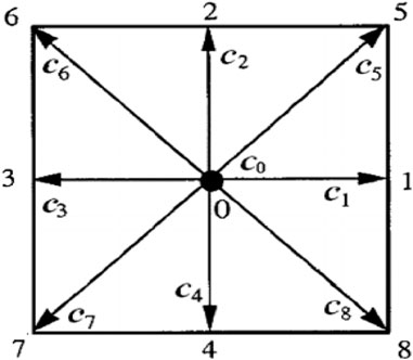
FIGURE 1. Two-dimensional nine-velocity particle model.
3 Problem description
The geometry of the problem under consideration is presented in Figure 2. A fixed square cylinder with an attached flat plate is placed inside a channel having length l and height H. D is the size of the cylinder, and L is the non-dimensional length of the plate. The length of the plate is systematically varied in the range 0.1–8.5. Specifically, plate length is varied with step size 0.1 in the range 0.1–2, with step size 0.2 in the range 2–6, and with step size 0.25 in the range 6–8.5. It is of note that the height of the plate is fixed at 0.2 throughout this study. The height H of the channel is fixed at 21, while the length l of the channel varies depending on the length of the plate. Furthermore, we selected an upstream distance, from the inlet to the cylinder, of LU = 10 times the size of the cylinder and a downstream distance, from the plate rear end to the outlet, of LD = 20 times the size of the cylinder. These domain locations are fixed for all chosen lengths of the attached plate. All the domain locations and plate lengths are non-dimensionalized using the size D of the cylinder.
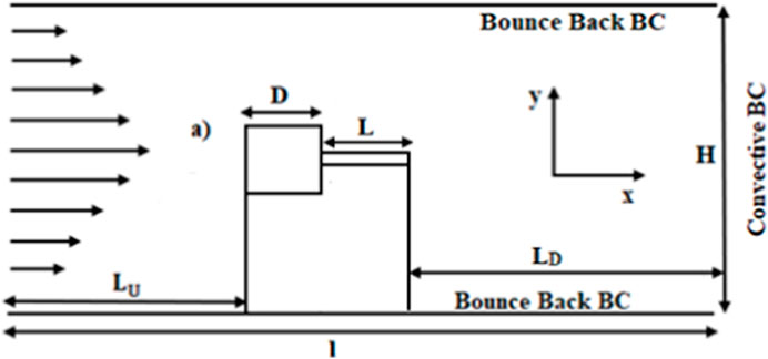
FIGURE 2. Schematic flow diagram.
The flow at the inlet is prescribed by the parabolic velocity (u = 4Uin (y/H)(1 – y/H); v = 0). One reason for choosing this velocity profile is that parabolic incoming flows are of practical relevance in most fluid flow problems. A second is that, in most previously published work, a uniform inflow velocity was chosen for flow control-related problems. We attempted to address the flow control mechanism around a square cylinder when the inflow velocity is parabolic. At the upper and lower channel walls and the cylinder surface, a no-slip boundary condition (
4 Grid independence and code validation
To ensure that the results of the current study were not influenced by the number of grid points on the surface of the square cylinder, a grid independence analysis was performed for flow past a single square cylinder at Re = 150. For this analysis, the mean drag coefficient, Strouhal number, and root-mean-square values of the drag coefficient were computed by dividing the cylinder’s surface into 10, 20, and 40 grid points (Table 1). In comparison to the other schemes, the results for the 20-point grid were more appropriate in terms of computation time and accuracy. Although a 40-point grid may produce more accurate results, it takes a great deal of computation time to reach convergence, and there is not much difference in results between the 20- and 40-point grids. On the other hand, a 10-point grid suffers from a lack of accuracy. Thus, all computations in this study were performed on a 20-point grid, D = 20. Islam et al. [40] and Guo et al. [41] also proposed a 20-point grid for convergence.
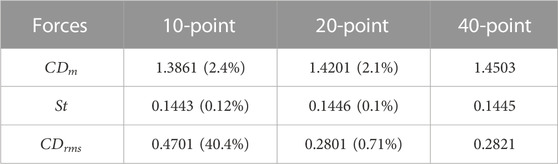
TABLE 1. Comparison of physical parameters for different grid sizes at
To confirm the validity of the code, the computations were performed for flow around a single square cylinder without a plate at Re = 150 to test whether our code is capable of capturing the important physics of flow around bluff bodies. The results are illustrated in terms of instantaneous contours of vorticity, streamlines, drag and lift coefficients, and power spectrum in Figure 3. In the vorticity graph (Figure 3A), the dashed lines indicate the clockwise vortices and the solid lines show the anticlockwise vortices. It can be noted that the incoming flow detaches from the front edges of the cylinder and rolls up to form vortices in the wake of a cylinder. These vortices move alternately in the domain, exhibiting the well-known Kármán vortex street behavior. In the streamlines graph (Figure 3B), a recirculating eddy can be observed adjacent to the rear lower corner of the cylinder, indicating vortex formation due to the merging of shear layers detaching from the upper and lower sides of the cylinder. The alternate movement of vortices is indicated by the waviness of streamlines in the wake region of the cylinder. Due to the unsteadiness in flow,
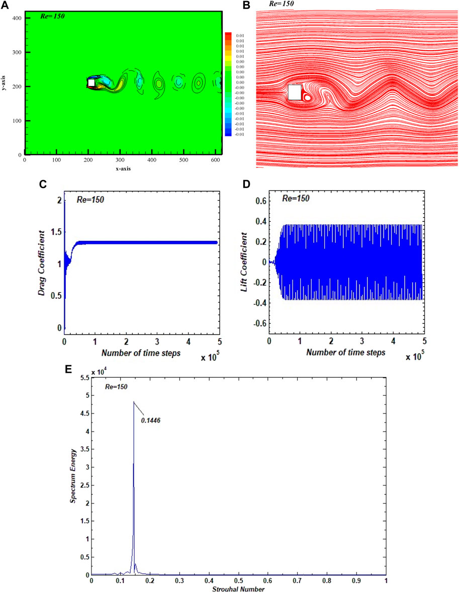
FIGURE 3. (A) Vorticity, (B) streamline, (C) drag coefficient, and (D) lift coefficient. (E) Power spectrum graphs for the flow past a single square cylinder for Re = 150.
5 Results and discussion
Flow around a square cylinder exhibits different modes with fluid force modifications in a case in which a controlling device is introduced in the wake [16, 48]. In the present case, when the length of the plate attached to the cylinder is systematically varied from 0.1 to 8.5, three major flow modes are observed. In accordance with certain characteristics of these flow modes, they are named the unsteady, transitional, and steady flow modes. These classifications depend on the flow structure observed in vorticity contours, behavior of streamlines behavior, temporal variations in the drag and lift coefficients, power spectrum analysis of the lift coefficient, Strouhal number, and RMS values of the drag and lift coefficients. This section presents only representative cases for each flow mode, keeping in mind the fact that all simulation results cannot be included in the manuscript for purposes of brevity and to avoid repetition. The effect of plate length on important flow parameters such as
5.1 Flow mode analysis
Figures 4A–F show observed vorticity contours for the different flow modes, corresponding to different plate lengths, at Re = 150. For the values of plate length
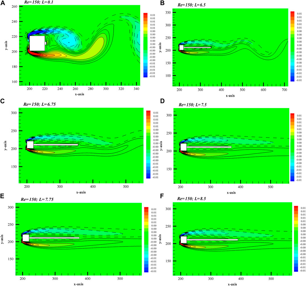
FIGURE 4. Vorticity graphs corresponding to different flow modes: (A,B) Unsteady, (C,D) Tranisent, and (E,F) Steady flow mode.
With each increment in plate length, the cross-wake region is minimized and comes closer to the plate surface. Due to the increased length of the plate, the merging of shear layers of opposite signs is delayed. It seems that the plate gradually controls the unsteadiness in flow. With plate lengths beyond 6.5, the transitional flow mode can be observed in the range
With a further increment in plate length (
Figures 5A–C show the streamlines corresponding to different flow modes observed from vorticity contours. In Figure 5A, the streamline pattern indicates periodic flow at the down-wake region for plate length
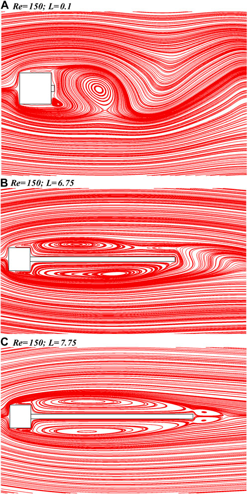
FIGURE 5. Streamlines graphs corresponding to different flow modes: (A) Unsteady, (B) Tranisent, and (C) Steady flow mode.
Figure 6; Figure 7 show the time-dependent variations in
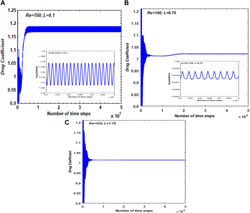
FIGURE 6.
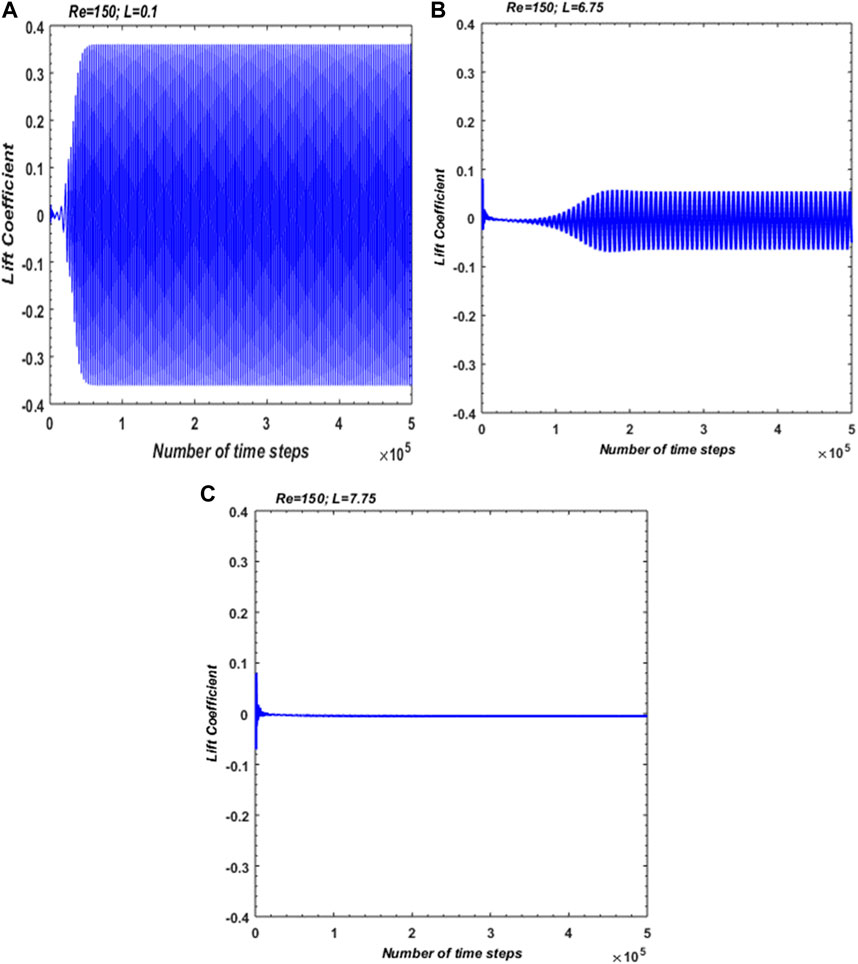
FIGURE 7.
The power spectra of
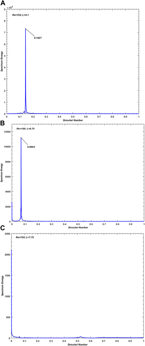
FIGURE 8. Power Spectrum graphs corresponding to different flow modes: (A) Unsteady, (B) Tranisent, and (C) Steady flow mode.
5.2 Statistical analysis of physical parameters
In this section, the effects of plate length on physical parameters such as
The variations in
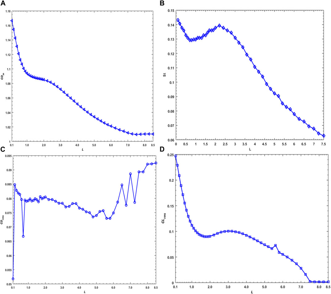
FIGURE 9. Variation of (A) average
Figure 9B represents the variations in
The variation in
Figure 9D shows
5.3 Analysis of reduction in physical parameters
Figure 10 shows the percentage differences in
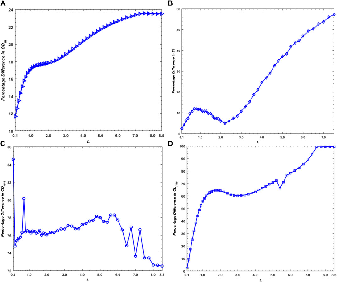
FIGURE 10. Percentage difference graphs: (A)
Note that the values of
Similar to
From Figure 10C, it can be seen that the highest-percentage reduction as compared to the SCWP in the case of
Figure 10D shows that in the unsteady flow mode range (
5.4 Effect of the plate on velocity fluctuations
The effect of increasing plate length on horizontal velocity fluctuations is depicted in Figures 11A–C, corresponding to the three observed flow modes as representative cases. Similar to the cases of other fluid flow parameters, these graphs also indicate the damping of velocity due to increasing plate length. Figure 11 shows the maximum velocity at the front corners of the cylinder regardless of increasing plate length. This is due to detachment of shear layers from the front corners of the cylinder. The minimum velocity can be observed in the wake region adjacent to the cylinder, which is due to the shielding effect of the cylinder. The velocity is then distributed randomly as the fluid flows in the wake of the cylinder. The plate plays a role in stabilizing the randomness of velocity, and the steady flow region and minimum velocity region are enlarged as its length increases. At L = 0.1, the velocity fluctuates unsteadily; this is then sufficiently controlled by the plate at L = 7.75 owing to the establishment of steady flow mode.
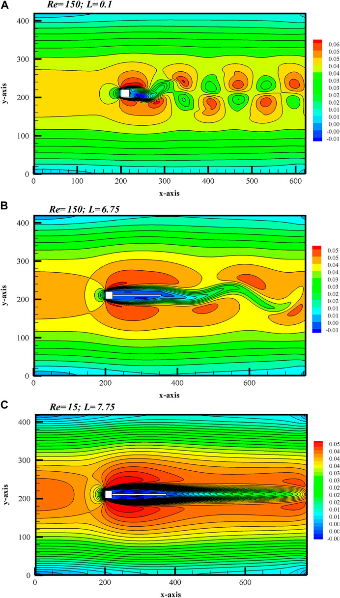
FIGURE 11. Velocity contours for (A) unsteady, (B) transient, and (C) steady flow modes.
6 Conclusion
The current study investigated the capacity of a flat plate attached to the rear side of a square cylinder to control the fluctuating forces and regulate vortex shedding using the lattice Boltzmann method. The plate length was varied in the range 0.1
1 Depending on the plate length, three different flow modes were observed: unsteady flow (
2 The amplitudes of the drag and lift force coefficients were found to be significantly reduced as plate length gradually increased and eventually became constant in the steady flow mode.
3 For the unsteady and transitional flow modes, the power spectrum of CL exhibited a single peak owing to the chaos-free behavior of the flow. However, due to the steadiness in
4 As plate length increased, flow parameters such as
Data availability statement
The raw data supporting the conclusion of this article will be made available by the authors, without undue reservation.
Author contributions
WA, AM, and SI performed modelling, computed results and prepared initial draft of manuscript. HR, IK, SN, and AM reviewed the draft for improvement. AM and IK improve results. All authors contributed to the article and approved the submitted version.
Conflict of interest
The authors declare that the research was conducted in the absence of any commercial or financial relationships that could be construed as a potential conflict of interest.
Publisher’s note
All claims expressed in this article are solely those of the authors and do not necessarily represent those of their affiliated organizations, or those of the publisher, the editors, and the reviewers. Any product that may be evaluated in this article, or claim that may be made by its manufacturer, is not guaranteed or endorsed by the publisher.
References
1. Gera B, Pavan K, Singh RK. CFD analysis of 2D unsteady flow around a square cylinder. J Appl Eng (2010) 1(3):602–10.
2. Golani R, Dhiman AK. Fluid flow and heat transfer across a circular cylinder in the unsteady flow regime. J Eng Sci (2014) 3(3):08–19.
3. Zdravkovich MM. Forces on a circular cylinder near a plane wall. Appl Ocean Res (1985) 7(4):197–201. doi:10.1016/0141-1187(85)90026-4
4. Park J, Kwon K, Choi H. Numerical solutions of flow past a circular cylinder at Reynolds numbers up to 160. KSME Int J (1998) 12(6):1200–5. doi:10.1007/bf02942594
5. Saha AK, Muralidhar K, Biswas G. Transition and chaos in two-dimensional flow past a square cylinder. J Eng Mech (2000) 2000(126):523–32. doi:10.1061/(asce)0733-9399(2000)126:5(523)
6. Sohankar A, Norberg C, Davidsona L. Simulation of three-dimensional flow around a square cylinder at moderate Reynolds numbers. Phys Fluids (1999) 11(2):288–306. doi:10.1063/1.869879
7. Perumal DA, Kumar GVS, Dass AK. Lattice Boltzmann simulation of viscous flow past elliptical cylinder. J Mech Eng (2012) 4(3):127–39.
8. Saha AK, Shrivastava A. Suppression of vortex shedding around a square cylinder using blowing. Sadhana (2015) 40(3):769–85. doi:10.1007/s12046-014-0331-9
9. Abograis AS, Alshayji AE. Reduction of fluid forces on a square cylinder in a laminar flow using passive control methods. In: COMSOL Conference in Boston (2013).
10. Chen M, Liua X, Liu F, Lou M. Optimal design of two-dimensional riser fairings for vortex-induced vibration suppression based on genetic algorithm. Fluid Dyn (2018) 1–25. arXiv:1801.03792.
11. Dey P, Das AK. Numerical analysis of drag and lift reduction of square cylinder. Eng Sci Technol Int J (2015) 18(4):758–68. doi:10.1016/j.jestch.2015.05.007
12. Furquan M, Mittal S. Flow past two square cylinders with flexible splitter plates. Comput Mech (2015) 55:1155–66. doi:10.1007/s00466-014-1110-5
13. Ghadimi P, Djeddi SR, Oloumiyazdi RH, Dashtimanesh A. Simulation of ow over a confined square cylinder and optimal passive control of vortex shedding using a detached splitter plate. Trans B: Mech Eng (2015) 22(1):175–86.
14. Chauhan MK, Dutta S, Singh B, Gandhi BK. Experimental investigation of flow over a square cylinder with an attached splitter plate at intermediate Reynolds number. J Fluids Structures (2018) 76:319–35. doi:10.1016/j.jfluidstructs.2017.10.012
15. Gallegos RKB, Sharma RN (2016). “ Dynamic behaviour of a flexible plate behind a circular cylinder: Numerical study on the effects of blockage and cylinder size.” Australasian Fluid Mechanics Conference, pp. 5–8.
16. Ali MSM, Doolan CJ, Wheatley C. Low Reynolds number flow over a square cylinder with splitter plate. Phys Fluids (2011) 23:1–12.
17. Mansy RE, Sarwar W, Rodriguez I, Bergada JM. Three dimensional structures of flow through a square cylinder with an upstream splitter plate and for several velocity ratios. In: Tenth International Conference on Computational Fluid Dynamics; Barcelona, Spain (2018). p. 1–13.
18. Barman B, Bhattacharyya S. Control of vortex shedding and drag reduction through dual splitter plates attached to a square cylinder. J Mar Sci Appl (2015) 14:138–45. doi:10.1007/s11804-015-1299-5
19. Bao Y, Tao J. The passive control of wake flow behind a circular cylinder by parallel dual plates. J Fluids Structures (2013) 37:201–19. doi:10.1016/j.jfluidstructs.2012.11.002
20. Kumar R, Selokar GR, Jhavar P, Kalariya S. Drag estimation of flow past a square cylinder using two splitter plate. Int J Adv Res Innovative Ideas Edu (2016) 2(1):371–80.
21. Abdolahipour S, Mani M, Taleghani AS. Pressure improvement on a supercritical high-lift wing using simple and modulated pulse jet vortex generator. Flow Turbulence Combustion (2022) 109:65–100. doi:10.1007/s10494-022-00327-9
22. Abdolahipour S, Mani M, Taleghani AS. Experimental investigation of flow control on a high-lift wing using modulated pulse jet vortex generator. J Aerospace Eng (2022) 35(5):05022001. doi:10.1061/(asce)as.1943-5525.0001463
23. Abdolahipour S, Mani M, Taleghani AS. Parametric study of a frequency-modulated pulse jet by measurements of flow characteristics. Physica Scripta (2021) 96(12):125012. doi:10.1088/1402-4896/ac2bdf
24. Taleghani AS, Shadaram A, Mirzaei M. Effects of duty cycles of the plasma actuators on improvement of pressure distribution above a NLF0414 airfoil. IEEE Trans Plasma Sci (2012) 40(5):1434–40. doi:10.1109/tps.2012.2187683
25. Salmasi A, Shadaram A, Taleghani AS. Effect of plasma actuator placement on the airfoil efficiency at poststall angles of attack. IEEE Trans Plasma Sci (2013) 41(10):3079–85. doi:10.1109/tps.2013.2280612
26. Mohammadi M, Taleghani AS. Active flow control by dielectric barrier discharge to increase stall angle of a NACA0012 airfoil. Arabian J Sci Eng (2014) 39:2363–70. doi:10.1007/s13369-013-0772-1
27. Mirzaei M, Taleghani AS, Shadaram A. Experimental study of vortex shedding control using plasma actuator. Appl Mech Mater (2012) 186:75–86. doi:10.4028/www.scientific.net/amm.186.75
28. Taleghani AS, Shadaram A, Mirzaei M, Abdolahipour S. Parametric study of a plasma actuator at unsteady actuation by measurements of the induced flow velocity for flow control. J Braz Soc Mech Sci Eng (2018) 40(4):173–13. doi:10.1007/s40430-018-1120-x
29. Sheikholeslam M, NooriTaleghani AS, Rahni MT. Surface acoustic waves as control actuator for drop removal from solid surface. Fluid Dyn Res (2021) 53(4):045503. doi:10.1088/1873-7005/ac12af
30. Rahni MT, Taleghani AS, Sheikholeslam M, Ahmadi G. Computational simulation of water removal from a flat plate, using surface acoustic waves. Wave Motion (2022) 111:102867. doi:10.1016/j.wavemoti.2021.102867
31. Malekzadeh S, Sohankar A. Reduction of fluid forces and heat transfer on a square cylinder in a laminar flow regime using a control plate. Int J Heat Fluid Flow (2021) 34:15–27. doi:10.1016/j.ijheatfluidflow.2011.12.008
32. Canpolat C, Sahin B. Influence of single rectangular groove on the flow past a circular cylinder. Int J Heat Fluid Flow (2017) 64:79–88. doi:10.1016/j.ijheatfluidflow.2017.02.001
33. Sohankar A, Khodadi M, Rangraz E, Alam MM. Control of flow and heat transfer over two inline square cylinders. Phys Fluids (2019) 31:123604. doi:10.1063/1.5128751
34. Zhou L, Li H, Tse TKT, He X, Maceda GYC, Zhang H. Sensitivity-aided active control of flow past twin cylinders. Int J Mech Sci (2023) 242:108013. doi:10.1016/j.ijmecsci.2022.108013
35. Chan AS. Control and suppression of laminar vortex shedding off two-dimensional bluff bodies. PhD Dissertation. Stanford, CA: Department of Mechanical Engineering, Stanford University (2012).
36. Wolf-Gladrow DA. Lattice-gas cellular automata and lattice Boltzmann models-an introduction. Berlin, Germany: Springer (2005).
37. Chapman S, Cowling TG. Mathematical theory of non-uniform gases. 3rd ed. Cambridge, UK: Cambridge University Press (1970).
38. Mohamad AA. Lattice Boltzmann method: Fundamentals and engineering applications with computer codes. 2nd ed. Berlin, Germany: Springer (2019).
39. Viggen EM. The lattice Boltzmann method with applications in acoustics. Master’s thesis. Trondheim, Norway: NTNU (2009).
40. Islam S, U, Manzoor R, Ying Z, C, Rashdi M, M, Khan A. Numerical investigation of fluid flow past a square cylinder using upstream, downstream and dual splitter plates. J Mech Sci Tech (2017) 31(2):669–87. doi:10.1007/s12206-017-0119-z
41. Guo Z, Liu H, Luo L-S, Xu K. A comparative study of the LBE and GKS methods for 2D near incompressible laminar flows. Comput Phys (2008) 227:4955–76. doi:10.1016/j.jcp.2008.01.024
42. Abbasi WS, Islam SU, Faiz L, Rahman H. Numerical investigation of transitions in flow states and variation in aerodynamic forces for flow around square cylinders arranged inline. Chin J Aeronautics (2018) 31(11):2111–23. doi:10.1016/j.cja.2018.08.020
43. Abbasi WS, Islam SU. Transition from steady to unsteady state flow around two inline cylinders under the effect of Reynolds numbers. J Braz Soc Mech Sci Eng (2018) 40:168. doi:10.1007/s40430-018-1083-y
44. Abbasi WS, Islam SU, Rahman H, Manzoor R. Numerical investigation of fluid-solid interaction for flow around three square cylinders. AIP Adv (2018) 8:025221. doi:10.1063/1.5004631
45. Abbasi WS, Naheed A, Islam SU, Rahman H. Investigation of optimum conditions for flow control around two inline square cylinders. Arabian J Sci Eng (2021) 46:2845–64. doi:10.1007/s13369-020-05303-x
46. Islam SU, Rahman H, Abbasi WS, Shahina T. Lattice Boltzmann study of wake structure and force statistics for various gap spacings between a square cylinder with a detached flat plate. Arabian J Sci Eng (2015) 40:2169–82. doi:10.1007/s13369-015-1648-3
47. Islam SU, Abbasi WS, Ying ZC. Transitions in the unsteady wakes and aerodynamic characteristics of the flow past three square cylinders aligned inline. Aerospace Sci Tech (2016) 50:96–111. doi:10.1016/j.ast.2015.12.004
48. Islam SU, Rahman H, Abbasi WS, Noreen U, Khan A. Suppression of fluid force on flow past a square cylinder with a detached flat plate at low Reynolds number for various spacing ratios. J Mech Sci Tech (2014) 28(12):4969–78. doi:10.1007/s12206-014-1118-y
49. Shahab M, Islam SU, Nazeer G. T-shaped control plate effect on flow past a square cylinder at low Reynolds numbers. Math Probl Eng (2021) 2021:1–19. doi:10.1155/2021/7562460
Keywords: cylinder, flow, laminar, plate, vortex shedding
Citation: Abbasi WS, Ismail S, Nadeem S, Rahman H, Majeed AH, Khan I and Mohamed A (2023) Passive control of wake flow behind a square cylinder using a flat plate. Front. Phys. 11:1132926. doi: 10.3389/fphy.2023.1132926
Received: 28 December 2022; Accepted: 13 March 2023;
Published: 03 April 2023.
Edited by:
Amin Chabchoub, Kyoto University, JapanReviewed by:
Cetin Canpolat, Çukurova University, TürkiyeArash Shams Taleghani, Aerospace Research Institute, Iran
Copyright © 2023 Abbasi, Ismail, Nadeem, Rahman, Majeed, Khan and Mohamed. This is an open-access article distributed under the terms of the Creative Commons Attribution License (CC BY). The use, distribution or reproduction in other forums is permitted, provided the original author(s) and the copyright owner(s) are credited and that the original publication in this journal is cited, in accordance with accepted academic practice. No use, distribution or reproduction is permitted which does not comply with these terms.
*Correspondence: Afraz Hussain Majeed, Y2hhZnJhemh1c3NhaW5AZ21haWwuY29t; Ilyas Khan, aS5zYWlkQG11LmVkdS5zYQ==