- Wuhan National Laboratory for Optoelectronics, Huazhong University of Science and Technology, Wuhan, China
In this work, a narrow-linewidth linearly polarized fiber amplifier with a record output power of 3.2 kW was achieved based on a homemade polarization-maintaining Yb-doped fiber corresponding to a slope efficiency of 79% and a 3 dB linewidth of 0.2227 nm. By examining various numerical aperture (NA) PMYDFs, the experimental investigation on expanding mode instability (MI) threshold in PM fiber amplifiers was put on display. And the results reveal that the MI threshold is enhanced by more than 370 W for every 0.004 decrease in core numerical aperture. Increasing the seed linewidth from 0.0454 nm to 0.0976 nm by adding 200 m polarization maintaining Ge-doped fiber the stimulated Brillouin scattering threshold increased from 805 W to above 3.2 kW. By applying the MI suppression method, a double-eight-shaped aluminum plate was adopted to coil the gain fiber, and the MI threshold increased by more than 1100 W.
1 Introduction
High-power narrow-linewidth fiber lasers or amplifiers with linearly polarized have been a major area of interest within the field of gravitational wave detection (GWD), non-linear frequency conversion (NFC), spectral beam combining (SBC), coherent beam combining (CBC) [1–6], and ultrafast lasers [7–12], etc., Over the last decade, ytterbium (Yb)-doped master oscillator power amplifiers (MOPAs) with linearly polarized ones have made great progress, and the power scaling has reached the muti-kilowatt level [13–15]. However, a number of destructive non-linear phenomena, including stimulated Raman scattering (SRS), stimulated Brillouin scattering (SBS), and thermal mode instability (MI), can jeopardize the stability of the laser system because of the high intensity in the fiber core [6, 16–18]. Among them, MI and SBS are the main limiting factors in the power scaling of a high-power narrow-linewidth linearly polarized MOPA system [18, 19].
A great deal of theoretical and experimental strategies has been carried out for mitigation of the MI or increasing its threshold power and SBS non-linearities in fiber laser systems. By taking into different strategies, some traditional methods to mitigate the MI in high-power all-fiber laser systems are to use few-mode fibers with tight coiling [18, 20], balance the heat load of a gain fiber [21, 22], design the spiral winding shape of fiber [23, 24], and tailor the gain fiber with high laser performance [25]. To some extent, tailing the gain fibers, such as confining Yb3+ doping in the fiber core [26, 27], varying core size in the longitudinal dimension [28, 29], and decreasing the numerical aperture (NA) of the large mode area (LMA) [30] fiber are theoretically and experimentally demonstrated to be capable of the effective suppression of the MI effects. And there are many theoretical and experimental studies for designing the common Yb-doped fiber (YDF) to solve the MI in random polarized fiber laser systems [30, 31]. However, few studies are reported on the fiber design solutions of MI in a linearly polarized fiber laser system due to its complexity of polarization-maintaining Yb-doped fiber (PMYDF) structure manufacturing. The traditional modified chemical vapor deposition (MCVD) technology combined with the solution doping process (SDP) is considered to be an easy and effective strategy to design the core NA of fiber and manufacture the excellent PMYDF [5, 32]. The detailed experimental studies on the influence of core NA of the PMYDF have a significant impact on the further power scaling of a high-power linearly polarized fiber laser.
Taking the various strategies of seed sources into consideration, some typical approaches to realize high-power narrow-linewidth linearly polarized fiber amplifiers are to use phase-modulated single-frequency laser (PMSFL) seeds [14, 15], super-fluorescent (SF) seeds [33, 34], random fiber laser (RFL) seeds [35, 36], and fiber oscillator laser (FOL) seeds [5, 13, 32]. And the multi-stage pre-amplifier and main-amplifier schemes based on the PMSFL seeds, SF seeds, and RFL seeds make the entire system complex and expensive while the scheme based on the FOL seeds is straightforward and practical due to its one-stage amplification. However, it is well known that the SBS effect is easily stimulated in amplifiers based on a FOL seed due to its temporal instability [14, 36]. Previous theoretical studies have shown that broadening the output linewidth of the laser can effectively suppress the SBS effects [37]. Increasing the bandwidth of output coupler (OC) fiber Bragg grating (FBG) is adopted to be a common way to broaden the linewidth [38], however, which is not conducive to suppressing temporal instability. In 2019, Li et al. reported that by inserting long transmission fibers in a seed laser [39], the temporal fluctuations could be flattened, while increasing the seed linewidth. Therefore, we want to introduce the method of inserting long transmission fibers into the polarization-maintaining (PM) MOPA systems based on a FOL seed and improve the SBS threshold, which is meaningful to the wider application of high-power narrow-linewidth linearly polarized amplifiers.
In this work, a maximum output power of 3.2 kW with a 3 dB linewidth of 0.2227 nm reached by applying the combination of a homemade PMYDF and a double-eight-shaped aluminum plate, corresponding to a slope efficiency of 79%. To the best of our knowledge, this is the highest output power from a linearly polarized narrow-linewidth fiber amplifier based on a FOL seed. The beam quality factor of M2x and M2y is 1.307 and 1.285 respectively at 2024 W. During the experimental process, three different NA PMYDFs were manufactured by MCVD combined with SDP, and the experimental relationship between the core NA and MI threshold in PM systems have been investigated for the first time. The results reveal that the MI threshold can be further scaled by decreasing the core NA. The threshold power increased from 1350 W to 1752 W and 2126 W for the case where the core NA drops from 0.068 to 0.064 and 0.060. The SBS effects are well-suppressed during the power scaling by broadening the seed linewidth.
2 Fiber fabrication and characterization
To study the MI threshold of fibers, three different NA PMYDF were manufactured by MCVD combined with SDP. The core and inner cladding dimensions of the PMYDF were designed and found to be 20 µm and 400 μm, respectively, as the relatively large-mode area may reduce non-linear effects and an adequate NA may ensure excellent beam quality. In addition, the 20/400 µm PMYDF has been a preferable choice for the high-power narrow-linewidth fiber amplifiers, and the fiber design based on NA investigation may provide a new sight for its further scaling. The concentration of the doping components in the SiO2 matrix directly affects the refractive index and NA during the process of solution doping. Hence, the doping components of Yb3+ and Al3+ were adopted to modulate the NA of the fiber. It should be noted that the increased Yb3+ will improve the absorption coefficient and NA of fiber simultaneously and excessive Yb3+ doping will cause crystallization. Therefore, Al3+ needs to be co-doped at the same time to improve the solubility of Yb3+ and eliminate crystallization. Meanwhile, the development of a center dip in the refractive index profile (RIP) may be avoided since Al3+ has minimal volatility. Since they all contribute positively to the RIP, the content of Yb3+ and Al3+ is accurately controlled so that NA can be confined to an effective range.
The technique in which PMYDF is prepared is almost identical to that described in our earlier work [32]. Specifically, the fabrication of active fiber preforms by MCVD combined with SDP can be divided into five fundamental steps: 1) barrier layer and soot layer deposition, 2) rare-earth solution doping, 3) thermal drying, 4) sintering, and 5) collapse. Different from the preparation of conventional Yb-doped fiber (YDF), the preparation of PMYDF needs to add two sets of processes: preform drilling and boron rod assembly. Subsequently, after achieving a well-prepared polarization maintaining (PM) preform, at temperatures of 1980°C, the preform assembly was pulled into a 20/400 µm fiber with a circular cladding and coated with a low-index polymer [5].
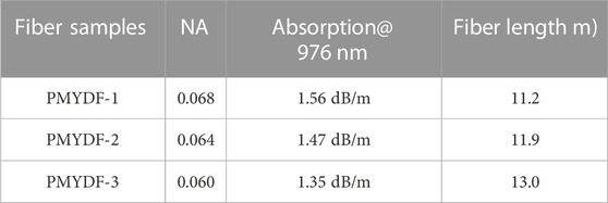
The detailed parameters of the three PMYDFs are shown in Table 1. In order to characterize the effect of NA on the MI threshold, the three kinds of PMYDF were fabricated with very close parameters for comparison. The RIP of PMYDF-3 with almost the same trend as the other two is shown in Figure 1A. The difference between the three fibers lies in the various core ions doping concentrations, which leads to a different NA. Figure 1B presents the cross-section of the PMYDF-3 exhibiting a 20.1 µm fiber core and a 400.2 µm inner cladding. The NA of the three fibers is 0.068, 0.064, and 0.060, respectively, corresponding to the cladding absorption coefficients at 976 nm of 1.56 dB/m, 1.47 dB/m, and 1.35 dB/m. As revealed in [40], Tao et al. demonstrated that the MI threshold was independent of dopant concentration as long as the same total pump absorption was maintained. Therefore, the only variable that affects the MI threshold is the difference in NA in our experiment.
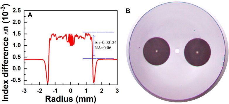
FIGURE 1. Characteristics of the PMYDF-3 (NA = 0.06) (A) Refractive index profile of the preform; (B) Image of the fiber cross-section.
3 Experimental setup
An all-fiber high-power narrow-linewidth linearly polarized MOPA was built up as shown in Figure 2, which has been described in our previous publication [5, 32]. The system contains a PM-FOL seed and the main PM amplifier. The PM-FOL seed consisting of a linear-cavity oscillator which is composed of a pair of gratings and an active fiber of 3.2 m is pumped by a fiber-pigtailed wavelength-stabilized 976 nm laser diode (LD). For polarization selection, the fast-axis wavelength of the high reflectivity (HR) FBG fitted the slow-axis wavelength of the output coupler OC FBG. The full width at half maximum bandwidth (FWHM) of the HR-FBG and the OC-FBG was 0.25 nm and 0.05 nm, respectively. The cladding absorption coefficient of the commercial PMYDF is approximately 4.95 dB/m at 976 nm. The cavity’s passive fiber measures around 1 m in length. Then, a PM cladding power stripper (CPS), a PM isolator (ISO), and a PM mode field adaptor (MFA) are closely followed. When the laser beam passes through the PM ISO, the PM ISO is used not only for blocking backward light but also for monitoring the backward SBS signal which originates from a final amplifier. The PM MFA is with an input size of 10/125 µm and an output size of 20/400 µm.
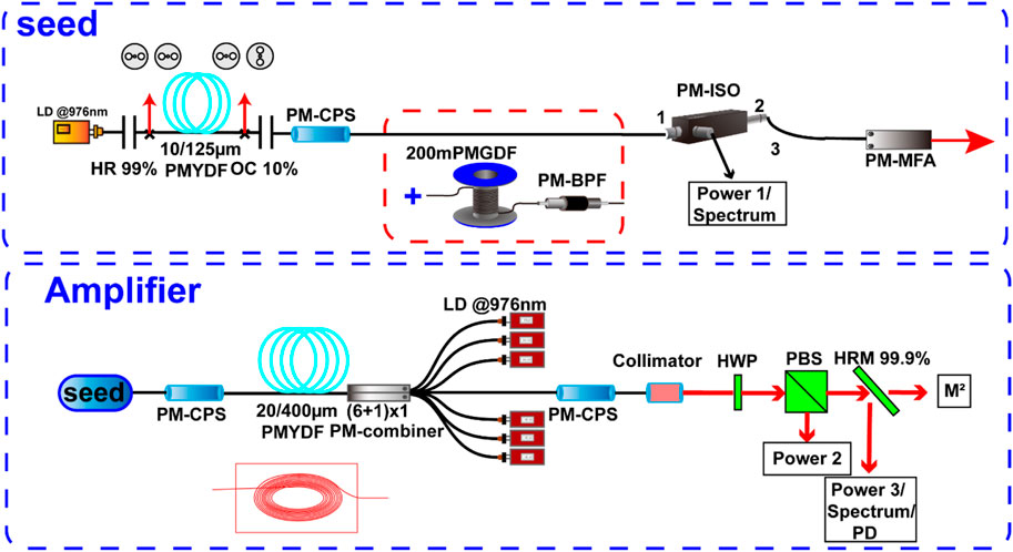
FIGURE 2. Scheme of experimental setup based on master oscillator power amplifier (MOPA). LD, laser diode; HR, high reflectivity fiber Bragg grating; OC, output coupler fiber Bragg grating; PM-CPS, polarization maintaining cladding power stripper; PMGDF, polarization maintaining Ge-doped fiber; BPF, bandpass filter; ISO, isolator; MFA, mode field adaptor; HWP, half-wave plate; PBS, polarization beam splitter; HRM, high reflection mirror; PD, photodetector.
The main PM amplifier is based on a counter-pumping configuration. The PM CPS after the seed is used to remove the cladding modes and pump lights in the fiber cladding which are generated by mode field mismatch from the seed and unabsorbed pump lights from the amplifier. A total pump absorption of 17.5 dB at 976 nm was adopted to trade off the laser efficiency against the SBS effects. The gain fiber length used in the amplifier is shown in Table 1. A runway-shaped aluminous plate was employed to coil the gain fiber for thermal management. The signal laser was injected from the coiled PMYDF with a diameter of ∼10 cm, and the largest diameter of the coiled PMYDF was ∼17 cm. The amplifier was pumped by non-wavelength-stabilized 976 nm LDs via a (6 + 1) × 1 PM combiner. Six 220/242 µm fibers with a NA of 0.22 make up the combiner’s pump ports, while its input and output signal ports are both 25/400 µm PM fibers with NA of 0.065 for the core and 0.46 for the cladding, respectively. A CPS and a collimator with a size of 30/400 µm are spliced behind the PM combiner. The output beam passes a half-wave plate (HWP) and a polarization beam splitter (PBS) for selecting the measured polarization. The PER is determined as 10log (Power 3/Power 2) shown in Figure 2. Then, a high reflection mirror (HRM) follows. A photodetector (PD) with a pinhole of a 1.5 mm diameter was placed to receive the reflected scattering lights. Three power meters, a spectrum analyzer, an oscilloscope, and an M2 analyzer are used to analysis of the characteristics of light. The whole MOPA system was mounted on an actively cooled heat sink with a cooling temperature of 16 °C to avoid thermal damage [32].
4 Experimental results and discussion
4.1 Laser performance and discussion of three PMYDFs
The contrast of output power characteristics: the output laser and backward power of the MOPA system versus the pump power and the frequency-domain characteristics of the amplifier by applying the three different NA PMYDFs were recorded and the results are shown in Figure 3. Since SBS has been a serious limiting factor to power scaling and is easy to be stimulated in high-power narrow-linewidth fiber amplifiers, hence, the backward power was recorded by a power meter named power 1, as depicted in Figure 2. Experimentally, it has been reported that reflectivity of 0.01%–1% indicates the amplifier working around the continuous wave (CW) SBS threshold [15]. By applying the PMYDF-1 in the amplifier, an output power of 1350 W was achieved with a slope efficiency of 80% shown in Figure 3A. The high laser efficiencies indicate that the fabricated fiber possesses a low background loss. During the power scaling experiments, a sudden increase of backward power occurred with the laser power beyond 820 W. This can be a sign of the SBS threshold. As a PM ISO was utilized to protect the seed source from damage, further power scaling was carried out for the research of fiber performance. The highest backward power was 1.52 W. It is well known that the energy transfer at a frequency of kHz level between the fundamental mode (FM) and the higher order modes (HOMs) indicates the occurrence of MI [41]. From Figure 3B, one can conclude that the frequency-domain signal remains stable at a laser power of 1290 W, and the frequency-domain signal lifting doesn’t occur. The fluctuation frequency in the range of 0–5 kHz appears in the Fourier spectrum with the further increased power to 1350 W, which reveals that the MI threshold of the PMYDF-1 is 1350 W. Figure 3C displays that the output power of 1752 W was achieved with a slope efficiency of 81% by applying the PMYDF-2. The highest backward power was 2.25 W. Similarly, the SBS threshold reaches when the laser power is approximately 820 W. And in Figure 3D, it can be seen that the MI threshold of the PMYDF-2 is 1752 W. Figure 3E exhibits that an output power of 2126 W was achieved with a slope efficiency of 80% by applying the PMYDF-3. The SBS threshold reaches at the laser power of 805 W, and the highest backward power was 3 W. The MI threshold of the PMYDF-3 is 2126 W shown in Figure 3F.
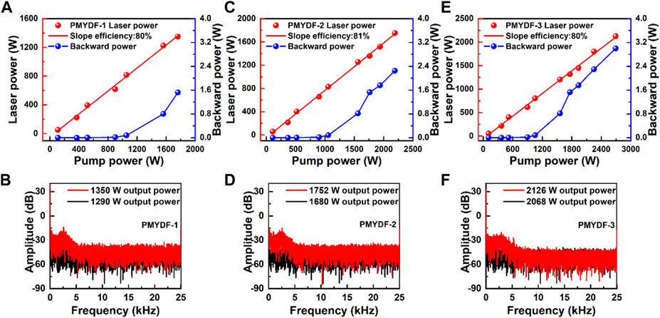
FIGURE 3. The laser and backward power of a MOPA system versus the pump power and the frequency-domain characteristics of the amplifier by applying the three different NA PMYDFs. (A) The laser performance of the PMYDF-1. (B) Frequency-domain characteristics before and after MI by applying the PMYDF-1. (C) The laser performance of the PMYDF-2. (D) Frequency-domain characteristics before and after MI by applying the PMYDF-2. (E) The laser performance of the PMYDF-3. (F) Frequency-domain characteristics before and after MI by applying the PMYDF-3.
The experimental results are arranged in detail shown in Table 2. There is a clear trend of elevation in the MI threshold by decreasing the NA of PMYDF, which is consistent with the finding in non-PM MOPA [30, 42]. For example, Tao et al. reported that the threshold power increases by 57%, 25%, 16%, and 11% for 20/400, 25/400, 30/400, and 30/250 fiber when the core NA decreases from 0.07 to 0.045 by numerical investigations [42]. In this work, the prominent aspect of our research is that the experimental investigations indicate MI threshold increases by more than 370 W for every 0.004 decreases in NA. This result mainly can be explained by the fact that the increased NA leads to the increasing number of modes supported by the core, which reduces the proportion of FM, so MI is more likely to occur. For the first time, accurate experimental data is given to illustrate the relationship between NA and MI threshold in 20/400 PMYDF, which is urgently needed for current power scaling in high-power narrow-linewidth linearly polarized fiber amplifiers [14, 19]. Although the gain fiber lengths employed in the amplifier have meter-scale differences, the previous experimental results show that the SBS threshold was affected little. The reasonable explanation of different backward power is that the SBS light passing through the gain fiber can be amplified, therefore, the backward power increased as the power was scaling.
4.2 The mitigation of SBS
To overcome the SBS observed in the present MOPA system, the common mitigation strategy which relied on increasing the length of 200 m polarization maintaining Ge-doped fiber (PMGDF) was applied to increase the linewidth of the laser shown in Figure 2. The PMGDF was spliced to the end of PM-CPS. As illustrated in [39], the stimulated Raman scattering (SRS) will be stimulated and accumulated due to the excessive transmission fiber. Therefore, a PM bandpass filter (BPF) was used to suppress the SRS. The 1064 nm BPF has the features of low insertion loss and 35 dB out-band suppression, with a passband of 8 nm and a maximum power handling of 30 W. Figure 4A depicts the evolution of seed linewidth before and after adding 200 m PMGDF. As is shown, the 3 dB linewidth of the original seed and broadened seed are 0.0454 nm and 0.0967 nm, respectively. In the following, we carried out the same laser experiment by applying the PMYDF-3 and investigated the improvement of the SBS threshold. As the laser power improves, as is shown in Figure 4B, the backward power keeps below the SBS threshold. And the highest backward power was 72 mW at the laser power of 2126 W. The results demonstrate the well-suppressed SBS effects and the MOPA system can afford higher laser output.
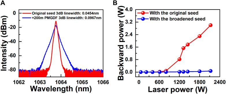
FIGURE 4. The results of the MOPA system before and after adding 200 m PMGDF. (A) The spectra of seed. (B) The backward power versus the laser power of a MOPA system by applying the PMYDF-3.
4.3 The mitigation of MI
Since the optimization of SBS effects was achieved, we considered realizing higher output power by suppressing the MI. The tight coiling method stands out due to its simplicity of implementation, which may be carried out without the construction of a more complex fiber or the selection of an exact wavelength. However, it is pointed out in [43] that the linearly polarized laser’s polarization direction is parallel to the direction of stress, which might greatly lessen the bend loss of the HOMs caused by the photo-elastic effect. The MI threshold for the commercial PMYDF is lower than those of the non-PMYDF in the same coil package as a result of this effect, which lessens the impact of the coil technique on MI suppression [44, 45]. Therefore, in order to attain a higher overall bend loss and avoid the drawback of reducing the bend loss of HOMs, the MI suppression approach must be developed.
As shown in Figure 5A, the original cooling system for fiber thermal management is a runway-shaped aluminous plate with a bending diameter ranging from 10cm to 17 cm. The seed laser was injected into the coil with a bending diameter of 10 cm and exited from the coil with a bending diameter of 17 cm. To increase the HOMs loss, a double-eight-shaped aluminum plate was adopted to suppress the MI and enhance the MOPA output power shown in Figure 5B. The difference is that the seed laser was injected into the coil and exited from the coil with the same bending diameter of 10 cm, and the maximum bending diameter of the coil was only 11 cm.
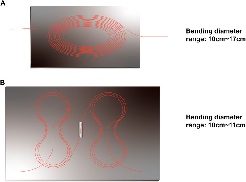
FIGURE 5. The cooling system for fiber thermal management. (A) A runway-shaped aluminous plate. (B) A double-eight-shaped aluminum plate.
Figure 6A shows the output power and backward power of the MOPA system versus the pump power, corresponding to a slope efficiency of 79%. As is shown, the SBS effects are well-suppressed during the power scaling and the backward power is 0.19 W at the laser power of 3.2 kW. To the best of our knowledge, 3.2 kW is the maximum output power of a narrow-linewidth linearly polarized fiber system based on a FOL seed. In Figure 6B, the frequency-domain spectra stay stable below the MI threshold for the laser power of 3.2 kW and the fluctuation frequencies appear in the range of 0–5 kHz for the laser power of 3.227 kW, which demonstrates the MI threshold is 3.227 kW. The inset of Figure 6B is a power display screenshot at the laser power of 3.227 kW.
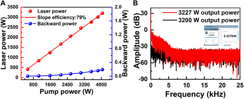
FIGURE 6. The laser performance of the PMYDF-3 when the MI is suppressed. (A) Laser power and backward power of a MOPA system versus the pump power. (B) Frequency-domain characteristics before and after MI. Inset: power display screenshot at the laser power of 3.227 kW.
One can conclude from the experiment that coiling the PMYDF in a double-eight-shaped aluminum plate is superior to coiling it in a runway-shaped aluminous plate, which increases the MI threshold by more than 1100 W. The reasonable explanation is that a higher total HOMs bending loss is obtained by coiling the gain fiber in a double-eight-shaped aluminum plate, which is consistent with our expectations. The coil diameter increases as the laser propagate along the fiber with a runway-shaped aluminous plate, resulting in the HOMs bending loss decreasing dramatically. However, the coil diameter remains almost unchanged with a double-eight-shaped aluminum plate, which is beneficial to realize a higher loss of HOMs.
In Figure 7A, the spectrum is shown for the 3.2 kW MI-suppressed MOPA which is achieved based on a higher loss of HOMs. The laser-to-Raman peak intensity ratio is larger than 27 dB, and the SRS effects are severe at this power level which should be effectively suppressed if further power scaling is needed. It can be explained that the accumulated SRS was caused by the 200 m PMGDF, which is a coincidence with the results in Ref. [39]. The SRS still exists because of the inadequate inhibition effect of BPF. Meanwhile, recent research reveals that several non-linear effects can also lead to MI, such as inter-modal four-wave mixing (IM-FWM) [46], SRS [6], etc. As shown in Figure 7A, there is no characteristic peak caused by the IM-FWM effect in the spectrum, and the content of SRS is not enough to trigger MI. The linewidth of a high-power narrow-linewidth linearly polarized amplifier matters a lot for its application, such as SBC and CBC. Consequently, the 3 dB linewidth of an SBS-suppressed and MI-suppressed MOPA was measured and shown in Figures 7B, C. The 3 dB linewidth versus the laser power is depicted in Figure 7B, corresponding to a linear fitting efficiency of 0.039 pm/W. And the 3 dB linewidth of a MOPA at 8.6 W and 3.2 kW are 0.0967 nm and 0.2227 nm, respectively.
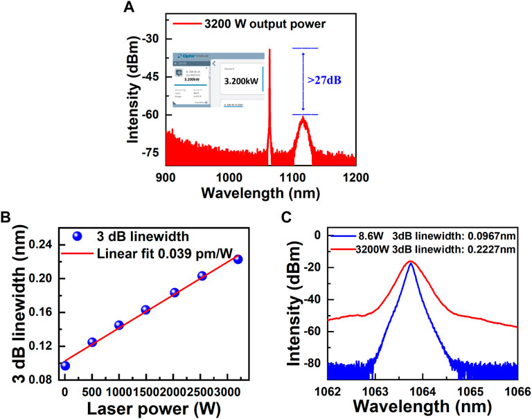
FIGURE 7. (A) Spectrum of the MOPA system at the laser power of 3.2 kW. (B) 3 dB linewidth versus the laser power. The 3 dB linewidths of 508 W, 1002 W, 1495 W, 2027 W, 2538 W, and 3.2 kW are 0.1247 nm, 0.1447 nm, 0.1629 nm, 0.1833 nm, 0.2030 nm, and 0.2227 nm, respectively. (C) Spectra of the MOPA system at the laser power of 8.6 W and 3.2 kW, and the 3 dB linewidth are 0.0967 nm, and 0.2227 nm, respectively.
Figure 8A reveals the evolution of the PER at different levels of laser power, and it can be seen that the PER keeps larger than 16.6 dB, which demonstrates a good polarization performance of the fiber. For the sake of the power-carrying capacity of the attenuation lens, a near-diffraction-limited output beam at the laser power of 2024 W was measured by an M2 analyzer with the M2x = 1.307 and M2y = 1.285.
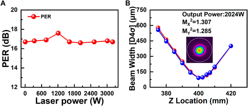
FIGURE 8. (A) PER versus laser power of a MOPA system. (B) Diffraction limited beam quality of the improved MOPA system at 2024 W after suppressing the SBS and mitigation of MI.
5 Conclusion
In conclusion, a maximum output power of 3.2 kW was achieved with a 3 dB linewidth of 0.2227 nm, corresponding to a slope efficiency of 79%. The PER remained larger than 16.6 dB during the power scaling. During the process of experiments, we investigated the effects of core NA on the MI of PMYDFs for the first time. It shows the MI threshold can be further scaled by decreasing the core NA, which is consistent with the results on non-PMYDF. For the case that the core NA decreases from 0.068 to 0.064 and 0.060, the threshold power increased from 1350 W to 1752 W and 2126 W. Increasing the seed linewidth from 0.0454 nm to 0.0976 nm by adding 200 m PMDGF, the SBS threshold increased from 805 W to above 3.2 kW. Compared with the method of coiling gain fiber in a runway-shaped aluminous plate, coiling it in a double-eight-shaped aluminum plate has a higher MI threshold, which enhances the output power by more than 1100 W. The results could provide a good reference for the power scaling of a narrow-linewidth linearly polarized system.
Data availability statement
The original contributions presented in the study are included in the article/supplementary material, further inquiries can be directed to the corresponding author.
Author contributions
SL: Conceptualization, Methodology, Validation, Investigation, Resources, Data Curation, Visualization. TL: Writing–Review & Editing. RX: Writing–Review & Editing. JC: Writing–Review & Editing. CS: Writing–Review & Editing ZZ: Writing–Review & Editing. YZ: Writing–Review & Editing. YX: Methodology, Validation, Writing–Review & Editing, Resources, Supervision, Project administration, Funding acquisition. HL: Resources, Project administration, Funding acquisition. JP: Project administration, Funding acquisition. ND: Supervision, Writing–Review & Editing. JL: Conceptualization, Validation, Supervision, Project administration, Funding acquisition.
Funding
National Natural Science Foundation of China under Grant No. 61905080.
Conflict of interest
The authors declare that the research was conducted in the absence of any commercial or financial relationships that could be construed as a potential conflict of interest.
Publisher’s note
All claims expressed in this article are solely those of the authors and do not necessarily represent those of their affiliated organizations, or those of the publisher, the editors and the reviewers. Any product that may be evaluated in this article, or claim that may be made by its manufacturer, is not guaranteed or endorsed by the publisher.
References
1. Jiang M, Ma P, Huang L, Xu J, Zhou P, Gu X. KW-level, narrow-linewidth linearly polarized fiber laser with excellent beam quality through compact one-stage amplification scheme. High Power Laser Sci Eng (2017) 5:e30. doi:10.1017/hpl.2017.31
2. Wang Y, Feng Y, Feng Y, Wang X, Wang X-J, Yan H, et al. 6.5 GHz linearly polarized kilowatt fiber amplifier based on active polarization control. Appl Opt (2017) 56:2760. doi:10.1364/ao.56.002760
3. Deschamps T, Ollier N, Vezin H, Gonnet C. Clusters dissolution of Yb3+ in codoped SiO2-Al2O3-P2O5 glass fiber and its relevance to photodarkening. J Chem Phys (2012) 136:014503. doi:10.1063/1.3673792
4. Ma P, Xiao H, Liu W, Zhang H, Wang X, Leng J, et al. All-fiberized and narrow-linewidth 5 kW power-level fiber amplifier based on a bidirectional pumping configuration. High Power Laser Sci Eng (2021) 9:e45–7. doi:10.1017/hpl.2021.32
5. Liao S, Luo T, Xiao R, Chu Y, Li H, Xing Y, et al. Spectral broadening suppressed by a gain-enhanced fiber in polarization maintaining high-power systems. IEEE Photon J (2022) 14:1–6. doi:10.1109/JPHOT.2022.3221834
6. Russell PSJ, Culverhouse D, Farahi F. Theory of forward stimulated Brillouin scattering in dual-mode single-core fibers. IEEE J Quan Electron (1991) 27:836–42. doi:10.1109/3.81397
7. Liu X, Yao X, Cui Y. Real-time observation of the buildup of soliton molecules. Phys Rev Lett (2018) 121:023905. doi:10.1103/PhysRevLett.121.023905
8. Zhang Z, Zhang J, Chen Y, Xia T, Wang L, Han B, et al. Bessel terahertz pulses from superluminal laser plasma filaments. Ultrafast Sci (2022) 2022:20221–6. doi:10.34133/2022/9870325
9. Liu X, Pang M. Revealing the buildup dynamics of harmonic mode-locking states in ultrafast lasers. Laser Photon Rev (2019) 13:1800333–9. doi:10.1002/lpor.201800333
10. Li X, Feng J, Mao† W, Yin F, Jiang J. Emerging uniform Cu2O nanocubes for 251st harmonic ultrashort pulse generation. J Mater Chem C (2020) 8:14386–92. doi:10.1039/d0tc03622f
11. Zhang C, Li X, Chen E, Liu H, Shum PP, han CX. Hydrazone organics with third-order nonlinear optical effect for femtosecond pulse generation and control in the L-band. Opt Laser Technol (2022) 151:108016. doi:10.1016/j.optlastec.2022.108016
12. Zhang C, Liu J, Gao Y, Li X, Lu H, Wang Y, et al. Porous nickel oxide micron polyhedral particles for high-performance ultrafast photonics. Opt Laser Technol (2022) 146:107546. doi:10.1016/j.optlastec.2021.107546
13. Wang Y, Ke W, Peng W, Chang Z, Feng3 YW, Sun Y, et al. 3 kW, 0.2 nm narrow linewidth linearly polarized all-fiber laser based on a compact MOPA structure. Laser Phys Lett (2020) 17:075101. doi:10.1088/1612-202X/ab8e42
14. Ren S, Ma P, Li W, Wang G, Chen Y, Song J, et al. 3.96 kW all-fiberized linearly polarized and narrow linewidth fiber laser with near-diffraction-limited beam quality. Nanomaterials (2022) 12:2541. doi:10.3390/nano12152541
15. Wang Y., Sun Y., Peng W., Feng Y., Wang J., Ma Y., et al. 3.25 kW all-fiberized and polarization-maintained Yb-doped amplifier with a 20 GHz linewidth and near-diffraction-limited beam quality. Aplied Opt (2021) 60:6331–6. doi:10.1364/ao.431081
16. Chu Q, Shu Q, Chen Z, Li F, Yan D, Guo C, et al. Experimental study of mode distortion induced by stimulated Raman scattering in high-power fiber amplifiers. Photon Res (2020) 8:595. doi:10.1364/prj.383551
17. Li W, Ma P, Chen Y, Song J, Lai W, Liu W, et al. 694 W sub-GHz polarization-maintained tapered fiber amplifier based on spectral and pump wavelength optimization. Opt Express (2022) 30:26875. doi:10.1364/oe.463082
18. Hejaz K, Shayganmanesh M, Rezaei-Nasirabad R, Roohforouz A, Azizi S, Abedinajafi A, et al. Modal instability induced by stimulated Raman scattering in high-power Yb-doped fiber amplifiers. Opt Lett (2017) 42:5274. doi:10.1364/ol.42.005274
19. Zhou P, Ma P, Liu W, Xiao H, Ren S, Song J, et al. High power, narrow linewidth all-fiber amplifiers. PROCEEDINGS SPIE (2022) 37. doi:10.1117/12.2614414
20. Beier F, Hupel C, Nold J, Kuhn S, Hein S, Ihring J, et al. Narrow linewidth, single mode 3 kW average power from a directly diode pumped ytterbium-doped low NA fiber amplifier. Opt Express (2016) 24:6011. doi:10.1364/oe.24.006011
21. Tao R, Ma P, Wang X, Zhou P, Liu Z. Theoretical study of pump power distribution on modal instabilities in high power fiber amplifiers. Laser Phys Lett (2017) 14:025002. doi:10.1088/1612-202X/aa4f8e
22. Yang B, Wang P, Zhang H, Xi X, Shi C, Wang X, et al. 6 kW single mode monolithic fiber laser enabled by effective mitigation of the transverse mode instability. Opt Express (2021) 29:26366. doi:10.1364/oe.433630
23. Su R, Tao R, Wang X, Zhang H, Ma P, Zhou P, et al. 2.43 kW narrow linewidth linearly polarized all-fiber amplifier based on mode instability suppression. Laser Phys Lett (2017) 14:085102–19. doi:10.1088/1612-202X/aa760b
24. Wang Y, Wang Y, Wang Y, Feng Y, Feng Y, Ma Y, et al. 2.5 kW narrow linewidth linearly polarized all-fiber MOPA with cascaded phase-modulation to suppress SBS induced self-pulsing. IEEE Photon J (2020) 12:1–15. doi:10.1109/JPHOT.2020.2997935
25. Zhang Z, Lin X, Zhang X, Luo Y, Liao S, Wang X, et al. Low-numerical aperture confined-doped long-tapered Yb-doped silica fiber for a single-mode high-power fiber amplifier. Opt Express (2022) 30:32333. doi:10.1364/oe.466111
26. Gong M, Yuan Y, Li C, Yan P, Zhang H, Liao S. Numerical modeling of transverse mode competition in strongly pumped multimode fiber lasers and amplifiers. Opt Express (2007) 15:3236. doi:10.1364/oe.15.003236
27. Liao L, Zhang F, He X, Chen Y, Wang Y, Li H, et al. Confined-doped fiber for effective mode control fabricated by MCVD process. Appl Opt (2018) 57:3244. doi:10.1364/ao.57.003244
28. Yang B, Zhang H, Shi C, Wang X, Pan Z, Wang Z, et al. High power monolithic tapered ytterbium-doped fiber laser oscillator. Opt Express (2019) 27:7585. doi:10.1364/oe.27.007585
29. Ye Y, Xi X, Shi C, Yang B, Wang X, Zhang H, et al. Comparative study on transverse mode instability of fiber amplifiers based on long tapered fiber and conventional uniform fiber. Laser Phys Lett (2019) 16:085109. doi:10.1088/1612-202X/ab2acf
30. Khitrov V, Minelly JD, Tumminelli R, Petit V, Pooler ES. 3kW single-mode direct diode-pumped fiber laser. Fiber Lasers XI: Technol Syst Appl (2014) 896189610V. doi:10.1117/12.2037453
31. Enbin W, Ang M, Eng S, Hang L, Hou Q, Hen D, et al. 50 μm core diameter Yb3+/Al3+/F− codoped silica fiber with M²<1.1 beam quality. Opt Lett (2016) 41:504–7. doi:10.1364/OL.41.000504
32. Liao S, Xiao R, Luo T, Zhang X, Xing Y, Chu Y, et al. kW-level, narrow-linewidth linearly polarized all-fiber amplifier based on homemade Yb-doped aluminosilicate polarization-maintaining fiber. Opt Fiber Technol (2023) 75:103163. doi:10.1016/j.yofte.2022.103163
33. Xu J, Ye J, Xiao H, Leng J, Liu W, Zhou P. In-band pumping avenue based high power superfluorescent fiber source with record power and near-diffraction-limited beam quality. High Power Laser Sci Eng (2018) 6:e46–6. doi:10.1017/hpl.2018.43
34. Ma P, Tao R, Wang X, Zhou P, Liu Z High-Power Narrow-Band and Polarization-, 27 (2015). p. 879–82.
35. Iangming JXU, Uang LONGH, Iang MANJ, Un JYE, Engfei PMA, Eng JIL, et al. Near-diffraction-limited linearly polarized narrow-linewidth random fiber laser with record kilowatt output. Photon Res (2017) 5:350–4. doi:10.1364/prj.5.000350
36. Du S, Qi T, Li D, Yan P, Gong M, Xiao Q. 10 kW fiber amplifier seeded by random fiber laser with suppression of spectral broadening and SRS. IEEE Photon Technol Lett (2022) 34:721–4. doi:10.1109/LPT.2022.3183025
37. Aoki Y, Tajima K, Murata S s, 6 (1987).Input power limits of optical fibers due to stimulated Brillouin scattering in fsk coherent optical transmission system
38. Zhang S, Zhang W, Jiang M, Liu W, Ma P, Li C, et al. Suppressing stimulated Raman scattering by adopting a composite cavity in a narrow linewidth fiber oscillator. Appl Opt (2021) 60:5984. doi:10.1364/ao.430054
39. Li T, Ke W, Ma Y, Sun Y, Gao Q. Suppression of stimulated Raman scattering in a high-power fiber amplifier by inserting long transmission fibers in a seed laser. J Opt Soc America B (2019) 36:1457. doi:10.1364/josab.36.001457
40. Tao R, Ma P, Wang X, Zhou P, Liu Z. Study of dopant concentrations on thermally induced mode instability in high-power fiber amplifiers. Laser Phys (2016) 26:065103. doi:10.1088/1054-660X/26/6/065103
41. Zhang F, Wang Y, Lin X, Cheng Y, Zhang Z, Liu Y, et al. Gain-tailored Yb/Ce codoped aluminosilicate fiber for laser stability improvement at high output power. Opt Express (2019) 27:20824. doi:10.1364/oe.27.020824
42. Tao R, Ma P, Wang X, Zhou P, Liu Z. Influence of core NA on thermal-induced mode instabilities in high power fiber amplifiers. Laser Phys Lett (2015) 12:085101. doi:10.1088/1612-2011/12/8/085101
43. Liu C-H, Galvanauskas A, Khitrov V, Samson B, Manyam U, Tankala K, et al. High-power single-polarization and single-transverse-mode fiber laser with an all-fiber cavity and fiber-grating stabilized spectrum. Opt Lett (2006) 31:17. doi:10.1364/ol.31.000017
44. Platonov N, Yagodkin R, De La Cruz J, Yusim A, Gapontsev V. 1.5kW linear polarized on PM fiber and 2kW on non-PM fiber narrow linewidth CW diffraction-limited fiber amplifier. Components Packaging Laser Syst (2017) III:10085100850M. doi:10.1117/12.2263926
45. Brar K, Savage-Leuchs M, Henrie J, Courtney S, Dilley C, Afzal R, et al. Threshold power and fiber degradation induced modal instabilities in high-power fiber amplifiers based on large mode area fibers. Fiber Lasers XI: Technol Syst Appl (2014) 896189611R. doi:10.1117/12.2042261
Keywords: polarization-maintaining Yb-doped fiber, MOPA, fiber laser, SBS, MI, NA control
Citation: Liao S, Luo T, Xiao R, Cheng J, Shu C, Zhang Z, Zhou Y, Xing Y, Li H, Peng J, Dai N and Li J (2023) 3.2 kW, 0.22 nm narrow-linewidth MOPA configuration fiber laser with a homemade polarization-maintaining Yb-doped fiber. Front. Phys. 11:1134745. doi: 10.3389/fphy.2023.1134745
Received: 30 December 2022; Accepted: 14 February 2023;
Published: 22 February 2023.
Edited by:
Shuo Liu, Hebei University of Technology, ChinaCopyright © 2023 Liao, Luo, Xiao, Cheng, Shu, Zhang, Zhou, Xing, Li, Peng, Dai and Li. This is an open-access article distributed under the terms of the Creative Commons Attribution License (CC BY). The use, distribution or reproduction in other forums is permitted, provided the original author(s) and the copyright owner(s) are credited and that the original publication in this journal is cited, in accordance with accepted academic practice. No use, distribution or reproduction is permitted which does not comply with these terms.
*Correspondence: Yingbin Xing, anN4eWIxMjMyMDA4QDEyNi5jb20=
 Shibiao Liao
 Tao Luo
 Zhilun Zhang