 Dan Song1†
 Jiupeng Xiong1†Man Luo1,2†Xiaobo Gong2Wenjun Huang2Chen Zeng1
 Yufeng Zhou1*
 Faqi Li1*Zhibiao Wang1,2,3*
- 1Key Laboratory of Ultrasound in Medicine and Engineering, College of Biomedical Engineering, Chongqing Medical University, Chongqing, China
- 2National Engineering Research Center of Ultrasound Medicine, Chongqing, China
- 3Chongqing Haifu Hospital, Chongqing, China
Introduction: Focused ultrasound ablation surgery (FUAS) has been emerging to treat a wide range of conditions non-invasively and effectively with promising therapeutic outcomes. The focusing capability of an ultrasound transducer (i.e., focus shift, beam distortion, and acoustic pressure at the focus) determines the ablation effects. However, the focus shift and focal beam distortion after ultrasound propagating through multi-layered heterogeneous viscoelastic biological tissues become significant and are found to deteriorate the performance of FUAS in clinics.
Methods: To achieve an accurate and reliable focal field among patients with large variations in the anatomical structures and properties, a spherical cavity transducer with open ends and sub-wavelength focal size (Li et al., APL, 2013,102:204102) was applied here. Both experimental measurements and numerical simulations were performed to characterize the acoustic fields of the spherical cavity transducer in water, the multi-layered concentric cylindrical phantom, and the heterogeneous tissue model (an adult male pelvis enclosed by porcine skin, fat, and muscle) and then compared with those of a conventional concave transducer at the same electrical power output.
Results: It is found that standing-wave focusing using the spherical cavity transducer results in much less focus shift (0.25λ vs. 1.67λ) along the transducer axis and focal beam distortion (−6 dB beam area of 0.71 mm2 vs. 4.72 mm2 in water and 2.55 mm2 vs. 17.30 mm2 in tissue) in the focal plane but higher pressure focusing gain (40.05 dB vs. 33.61 dB in tissue).
Discussion: Such a highly accurate and reliable focal field is due to the excitation at an appropriate eigen-frequency of the spherical cavity with the varied media inside rather than the reverberation from the concave surface. Together with its sub-wavelength focal size, the spherical cavity transducer is technically advantageous in comparison to the concave one. The improved focusing capability would benefit ultrasound exposure for not only safer and more effective FUAS in clinics, but also broad acoustic applications.
1 Introduction
Focused ultrasound ablation surgery (FUAS) has been emerging as a revolutionary and non-invasive therapy for a wide range of conditions, including uterine fibroids, adenomyosis, and solid tumors of the breast [1], prostate [2], liver [3], pancreas, kidney, bone [4], and brain [4–7]. It can improve the patient’s healthcare and quality of life with significant social and economic benefits [2, 8]. The operating principle of FUAS can be briefly described as focusing the ultrasound wave generated outside the human body on a target inside. The absorption of ultrasound waves by the tissue in the focal region leads to a rapid rise in temperature, permitting the tumor ablation within seconds while avoiding damage to the surrounding normal tissues [6, 9].
Ultrasonic focusing could be achieved by using an acoustic lens, a concave transducer, or a phased array [10–12]. When the ultrasound wave propagates and focuses in the multi-layered heterogeneous tissues, diffraction and refraction at the interfaces [13] result in focus shift and focal beam distortion [14–16]. Such a focus shift in soft tissue can reach a non-negligible scale. ter Haar et al. predicted numerically that the focus shift can be up to 3.4λ in bovine liver tissue away from its geometric position, where λ is the wavelength [17]. By introducing a curved tissue layer, the focus was reported to shift 6.7λ for a weakly focused low-frequency transducer (i.e., frequency of 0.5 MHz and f# of 5) and 3.5λ for a strongly focused high-frequency transducer (i.e., frequency of 1.75 MHz and f# of 2) [18]. The effects of the focus shift and focal beam distortion would be more critical if the ultrasound beams pass through the bone (i.e., rib and skull) or chest wall, where strong reflections induce high energy loss and dramatic beam distortion. It was reported that in the case where ultrasound propagates through bones and focuses in the kidney, an 11.0 dB drop in the spatial peak-temporal average acoustic intensity, ISPTA, and splitting of focus can be observed [19]. In the case of transcranial FUAS, a hot spot induced by the superficial secondary pressure peak on the skull [20] and shear waves with large displacement were found [21]. The significant focus shift and focal beam distortion in the multi-layered heterogeneous tissues seriously affect the precision and safety of FUAS.
In order to achieve a desired focus at the desired position in the heterogeneous media, phased array transducers are often used [14, 22–25]. By introducing extra phase offsets and amplitude distributions to all array elements, wave aberration due to the refraction at the tissue interfaces can be compensated. The compensation as well as the cost and complexity of the control and channel assembly increase dramatically with the number of independent elements. Meanwhile, some wavefront distortion correction methods have been proposed. Fink et al. proposed an adaptive focusing technique by using the time-reversal method [24], in which a point source was introduced in the presence of a hydrophone. The wavefront emitted by the hydrophone is recorded on the therapeutic array after propagation through the heterogeneous media and then time-reversed for emission in order to achieve the desired focus. However, the time-reversal method requires a strong scatter or a hydrophone at the preferred position [24] as a point source [26], which limits its clinical applications. Furthermore, by setting a virtual acoustic point source in a 3D finite differences simulation using computational tomography (CT) data, the focus shift in the transcranial brain tissue can be decreased to 0.47λ [23], and the energy deposition at the focus in vivo increases to 10 dB higher than that without any corrections [23, 26]. Ebbini et al. proposed a pseudo-inverse focus pattern synthesis method for the generation of precise focusing and heating [22]. Hynynen et al. employed a back-projected phase correction method based on magnetic resonance imaging (MRI) data to deduce the beam distortion and largely recover the peak intensity in multiple layers [14]. In the case of transcostal FUAS, several focusing methods were proposed to minimize the heating on the ribs’ surface while maintaining high intensities at the focus [27]. Binarized apodization used the geometric ray tracing from the desired focal point to deactivate the sources of a 254-element random phased array shadowed by ribs [28]. Bobkova et al. optimized the amplitude-phase distributions at the surface of the radiator using the Rayleigh integral of the velocity distribution between the ribs with the inclusion of diffraction effects and achieved a 23% gain in the peak intensity and 6.5% less power losses on the ribs [27]. Gélat et al. quantitatively compared different focusing methods through human ribs and found that the constrained method, which uses the boundary element method (BEM) as the forward model, offers greater potential than the others in terms of improving the focusing capability as well as diminishing the acoustic energy deposition on the rib [29]. Incorporating a high-performance focusing method with a suitable forward model based on actual 3D anatomical data makes a desired acoustic field in heterogeneous tissues theoretically possible [30]. However, it is noted that such numerical simulations are extremely time-consuming [15] and require extensive computational resources [23], which hinder the clinical application. Haqshenas et al. proposed a multiple-domain BEM that iteratively solves the ultrasound wave propagation problems within a few minutes and has great potential for FUAS planning [31].
In our previous study, a spherical cavity transducer with two open ends had been designed and evaluated [32]. Sub-wavelength ultrasonic focus and more than three times the pressure focusing gain (PFG) were achieved [32]. In this work, the produced acoustic field in heterogeneous media (multi-layered phantoms and an adult male pelvis enclosed with porcine skin, fat, and muscle) was simulated and measured to quantify the focus shift, focal beam distortion, and the PFG and then compared with those of a concave transducer. It is found that the spherical cavity ultrasound transducer can obviously decrease positioning error to a sub-wavelength scale, and effectively suppress the wavefront distortion in heterogeneous media, which may provide a revolutionary focusing method to improve the precision and safety of FUAS in situ.
2 Materials and methods
The acoustic fields and focusing capabilities of a concave ultrasound transducer and a spherical cavity transducer in three media, deionized and degassed water, multi-layered tissue-mimicking phantom (namely Phantom, see Figure 1B), and heterogeneous viscoelastic tissues (namely Tissue, see Figure 1C), were investigated both numerically and experimentally. The Phantom was made of five kinds of gel (types I-V) prepared with an aqueous solution with different percentages of acrylamide, methylene bisacrylamide, ammonium persulfate, sodium metabisulfite, and tetramethylethylenediamine. 280 g of egg white were added to gel types II and V, and about 0.6 g of graphite was added to gel type IV and V to increase the acoustic attenuation and material heterogeneity. The aqueous solution was poured into coaxial cylinder molds in different radii (r1 = 50.57 mm, r2 = 63.21 mm, r3 = 75.86 mm, r4 = 88.50 mm, H = 100 mm, angles of I-II and IV-V are 145° and 215°, respectively) and then solidified at room temperature of 25
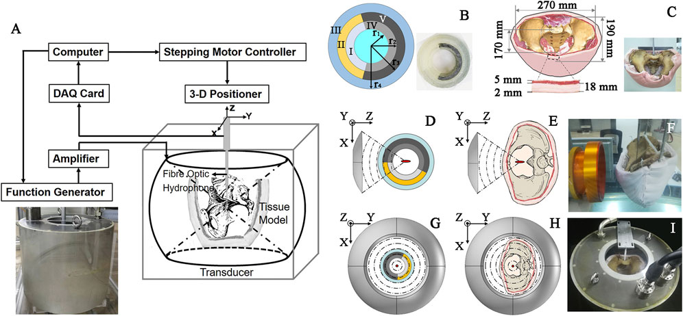
FIGURE 1. Schematic diagram of (A) the acoustic field mapping in different media with an inset of photograph of the spherical cavity transducer, (B) multi-layered concentric-cylinder tissue phantom (r1 = 50.57 mm, r2 = 63.21 mm, r3 = 75.86 mm, r4 = 88.50 mm, H = 100 mm, angles of I-II and IV-V are 145° and 215°, respectively) with an inset of its photo, (C) an adult male pelvis enclosed by porcine skin, fat, and muscle with an inset of its photo, concave transducer through (D) Phantom and (E) Tissue, spherical cavity transducer through (G) Phantom and (H) Tissue, and the photo of acoustic field mapping using (F) the concave and (I) spherical cavity transducers in Tissue.
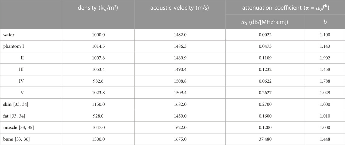
TABLE 1. Acoustic properties of phantom and tissues.
The experimental setup is shown in Figure 1A. A spherical cavity transducer with an inner radius of 240 mm, aperture height of 394 mm, and two open ends (see inset in Figure 1A) was immersed in degassed and deionized water [temperature of 20
Numerical simulation was conducted with the finite element method (FEM) software COMSOL Multiphysics (v5.2, Burlington, MA) and MATLAB (MathWorks, Natick, MA). In order to obtain the eigen-frequencies of the spherical cavity transducer, a frequency sweep was conducted in the pressure acoustics frequency domain module by solving the Helmholtz equation. The simulation model was set as 2D axisymmetric. Under the assumption of small-amplitude excitation, a linear acoustic wave propagation model with attenuation by ignoring the non-linear term in the Westervelt equation (38) was used in the simulation.
where
Here, we apply Huygens’ principle to explain the phenomenon of acoustic wave propagation in multi-layered or inhomogeneous media and, consequently, the focus shift. The wavefront is regarded as a secondary sound source, and the TW propagating in the Lth-layer medium with the viscous loss can be expressed as
where
In Eqs. 2, 3, the particle velocity refraction coefficient
where
In addition, another key issue of the focusing capability of the transducers, PFG, is defined as:
where
where
3 Results
3.1 Focus shift
The acoustic field produced by a focused transducer was first calculated using COMSOL and k-Wave toolbox, and the differences between them in Benchmark 1 and 3 are acceptable (see Supplementary Figure S1 in the Supplementary Information), which validates our simulation protocol. The normalized acoustic pressure distributions of the spherical cavity and concave transducers along the X, Y, and Z axes are shown in Figure 2. It is observed that an SW acoustic field is formed inside the spherical cavity transducer with antinodes every half wavelength (see the inset in Figure 2B). As listed in Table 2 and shown in Figure 3, the measured focus shifts of TW (SW) focusing in the X, Y, and Z axes are 0.072 ± 0.025λ (0.000 ± 0.000λ), 0.087 ± 0.043λ (0.009 ± 0.020λ), and 1.174 ± 0.043λ (0.233 ± 0.049λ) for Phantom, and 0.116 ± 0.025λ (0.045 ± 0.000λ), 0.464 ± 0.025λ (0.116 ± 0.025λ), and 1.661 ± 0.034λ (0.254 ± 0.026λ) for Tissue, respectively. A significant difference between TW and SW with p < 0.05 is demonstrated using the ANOVA test. It was also observed that TW focus shifts toward the transducer in Phantom while shifting forward along the Z axis in Tissue. Moreover, the focus shift of TW is only obvious along the Y axis in Tissue. In comparison, the focus shifts for SW in both Phantom and Tissue are smaller than 0.25λ but with large side lobes in the Z axis, while those in the X and Y axes are negligible (<0.05λ).
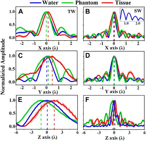
FIGURE 2. Comparison of the acoustic pressure distributions of (A, C, E) traveling wave (TW) by a concave transducer and (B, D, F) standing wave (SW) by a spherical cavity transducer along the X, Y, and Z axes when ultrasound propagates through water (blue curves), Phantom (green curves), and Tissue (blue curves), the inset in (B) showing the antinodes every half wavelength.
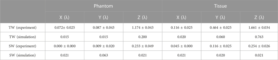
TABLE 2. Comparison of the focus shifts of the TW and SW acoustic fields in the experiment and simulation.
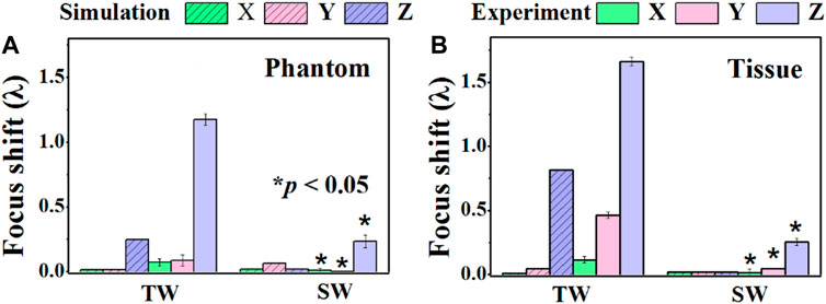
FIGURE 3. Comparison of the focus shifts produced by the traveling wave (TW) by a concave transducer and the standing wave (SW) by a spherical cavity transducer along the X, Y, and Z axes when ultrasound propagates through (A) Phantom and (B) Tissue. *: significant difference between TW and SW, p < 0.05.
The simulated focus shifts of TW (SW) focusing in the X, Y, and Z axes are 0.015λ (0.021λ), 0.015λ (0.063λ), and 0.200λ (0.021λ) in Phantom, and 0.020λ (0.021λ), 0.060λ (0.020λ), and 0.763λ (0.021λ) in Tissue, respectively. It is noted that all media in the simulation have excellent geometric symmetry and isotropy in the acoustic velocity, attenuation, and medium density. Therefore, there is no significant focus shift (<0.1λ) along the X and Y axes. The slightly larger focus shifts of SW may be due to the size of the simulation grid. In contrast, along the Z axis, the focus shift is more significant, especially in Tissue (0.79λ), but insignificant for SW (0.021λ). Altogether, both simulation and measurement results reveal that SW focusing through heterogeneous media by a spherical cavity transducer could confine the focus around its geometric position, especially a dramatic decrease of focusing shift in the Z axis.
3.2 Focal beam distortion
Ultrasound beam profiles with contours in the axial (X-Z) and radial (X-Y) planes of TW and SW focusing through different media are shown in Figures 4, 5. Compared with those in water, the focal regions in Phantom and Tissue become irregular and larger with several significant side lobes. The −6 dB focal area of SW (TW) focusing increases with the increasing geometric complexity of propagation media from water to Phantom and Tissue as listed in Table 3. In TW focusing, the largest −6 dB focal area is 48.88 mm2 in Phantom, ∼1.8 times as large as that in water, which likely attributes to the refraction and wavefront distortion due to the axially asymmetric phantom compositions. In comparison, the −6 dB focal areas of SW focusing in Phantom and Tissue are only ∼1.3 times those in water. The beam distortion in the radial focal plane is found more obvious than that in the axial focal plane in the experiment. In Tissue, the −6 dB focal area is more than 3.5 times that in water for both TW and SW focusing due to the heterogeneous media with complex anatomical structures. However, there is almost no enlargement of the −6 dB focal area in Tissue compared with that in water in the simulation, but only slight changes to the beam shapes with −18 dB of spatial peak pressure, which may be because the tissue in the same anatomical domain simplified as a homogenous medium in the simulation suppresses the refraction effects on the beam profile. Moreover, even for the bionic tissues, the sub-wavelength focusing capability (λ2 = 5.18 mm2) of the spherical cavity transducer is still valid with a −6 dB focal area of 2.55 mm2 in the experiment and 2.00 mm2 in the simulation, respectively.
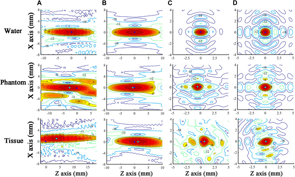
FIGURE 4. Ultrasound beam profiles in the axial (X-Z) focal plane of TW focusing in the (A) experiment and (B) simulation, and SW focusing in the (C) experiment and (D) simulation through water, Phantom, and Tissue. The acoustic focus and the origin of scanning coordinates (acoustic focus in water) are marked as cyan and blue dots, respectively. The regions with a normalized pressure larger than −9 dB are in color.
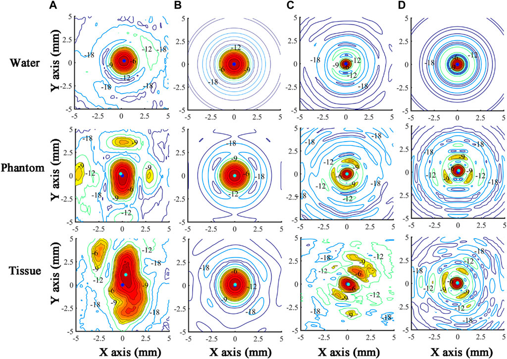
FIGURE 5. Ultrasound beam profiles in the radial (X-Y) focal plane of TW focusing in the (A) experiment and (B) simulation, and SW focusing in the (C) experiment and (D) simulation through water, Phantom, and Tissue. The acoustic focus and the origin of scanning coordinates (acoustic focus in water) are marked as cyan and blue dots, respectively. The regions with a normalized pressure larger than −9 dB are in color.
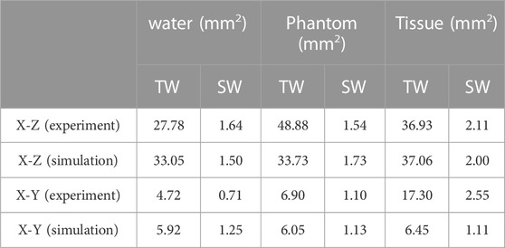
TABLE 3. Comparison of the −6 dB focal area of the TW and SW acoustic fields in the experiment and simulation.
3.3 Pressure focusing gain
The PFGs of SW and TW focusing on different cases are listed in Table 4. It is found that the PFG of SW focusing is at least 7 dB larger than that of TW focusing. The decrease in PFG is more significant in Tissue than in Phantom, 32.53 dB vs. 16.05 dB for SW and 7.85 dB vs. 1.15 dB for TW, due to the larger acoustic attenuation and impedance variations in the propagation media. Multi-layered tissues have a much larger disturbance on the wavefront of SW than that of TW, resulting in a sharp drop in PFG. In contrast, variations of the PFGs in the simulation are smaller than those in the experiment. Even though SW focusing is more beneficial to achieve a much higher PFG, we found that even in Tissue, the PFGs of SW focusing in the experiment and simulation are 40.05 and 49.27 dB, respectively.
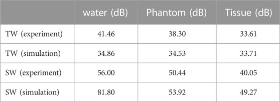
TABLE 4. The pressure focusing gain of TW and SW focusing in different media.
4 Discussion
The focus shift of TW and SW focusing in heterogeneous media (i.e., Phantom and Tissue in our experiment) is mainly induced by refraction at the interfaces on the ultrasound beam propagation path. According to Snell’s law, the refraction angle of the ultrasound beam is dependent on the sound speed of materials on the interface. Because of the faster sound speed of each phantom (1486–1509 m/s) compared with that of water (1482 m/s), the refraction angle of the ultrasound beam is larger than the incident one at the water-phantom interface, which attributes to the backward shift of TW focusing in Phantom [40]. Moreover, wavefront disturbance induced by the medium heterogeneity also contributes. However, the TW focus shifts forward along the Z axis in Tissue since the dominant fat has a smaller sound speed (1450 m/s). In Tissue, the focus shift of TW is only obvious along the Y axis due to the pelvis asymmetry. Altogether, it suggests that the focus shift in the axial direction is mainly induced by the refraction at the interfaces of multiple media layers, while that in the radial axis is dependent on the geometric asymmetry of the propagating media but at a much smaller magnitude. It should be mentioned that the refraction and wavefront distortion also have the effect of defocusing, which increases the phase deviation of the wavefront and subsequently leads to a distortion of the focal region as well as a decrease in the PFG. It is found that a typical peri-nephric fat in the thickness range of 2–4 cm would result in a derated intensity of up to 62% and a transverse focus shift of up to 1.08 mm at 0.8 MHz in comparison to a hypothetical patient with no per-nephric fat [41]. Furthermore, the fat close to the transducer (i.e., subcutaneous fat) produces a greater defocusing effect than that close to the ablation target (i.e., peri-nephric fat), which is because the wider cone necessarily passes through a greater area of heterogeneous fat tissue for more significant phase aberration.
Both our experimental and numerical results have demonstrated that, compared with TW focusing via a conventional concave transducer, SW focusing via a spherical cavity transducer benefits to achieve a smaller focus shift and less focal beam distortion but a higher PFG. One of the most important reasons is the achievement of acoustic resonance in a spherical cavity which allows a steady acoustic field with an accurate focus position. Using voltage and current signals as feedback, the eigen-frequency of the transducer can be tracked to maintain the resonance. Its theoretical value is given by
where
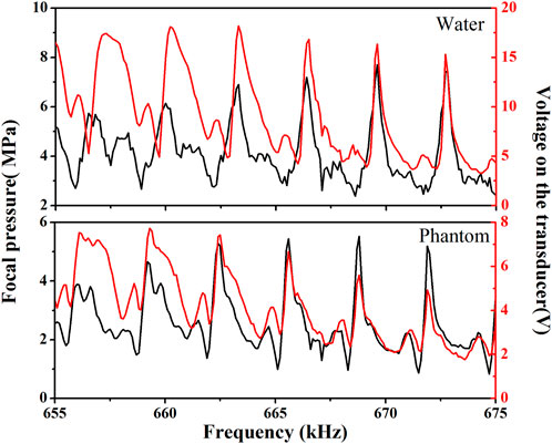
FIGURE 6. The frequency-dependent acoustic pressure at the focus (black) and voltage signal of the spherical cavity transducer (red) for SW focusing through water (upper panel) and through Phantom (lower panel).
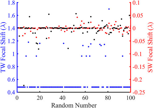
FIGURE 7. Comparison of the focus shifts in the traveling wave (TW) and standing wave (SW) modes over 100 random simulations. The blue and red ordinates are the TW and SW focus offsets, respectively, and the abscissa represents the random number. The blue, black, and red dots represent the focal shift distributions for TW at 680.2 kHz, SW at 680.2 kHz, and SW at the corresponding resonant frequencies, respectively.
There are some limitations to this investigation. Firstly, the simulation did not consider the non-linear effects in the acoustic wave propagation that transfer the fundamental acoustic energy to the high-order harmonics. In the FUAS, the power applied to the transducer generates finite-amplitude acoustic waves on the transducer surface. The generation of high-order harmonics leads to higher total acoustic attenuation, that is, frequency-dependent in power law, a smaller focal beam size, and the acoustic focus shifting away from its geometric position. Therefore, the deposited acoustic energy in the tissue with the inclusion of non-linear acoustic effects is much larger than that in linear acoustics for a larger coagulative necrosis, faster temperature elevation, and less treatment duration for ablating a certain-sized tumor. Because of the longer propagation distance and higher PFG of a spherical cavity transducer, the acoustic non-linear effects are more evident in SW focusing than in TW focusing of a concave transducer. However, establishment of the model is quite challenging. The Khakhlov-Zabolotskaya-Kuznetsov (KZK) equation is usually used in the simulation of a focused ultrasound field at high acoustic intensity (i.e., >1,000 W/cm2). It is based on a parabolic assumption of diffraction effects, that is, generally limited to the simulation of a weakly focused beam with a focusing angle of less than 32° [44]. Alternatively, an axisymmetric isothermal multi-relaxation-time lattice Boltzmann method (MRT-LBM) was established to numerically analyze the acoustic field of the spherical cavity transducer [45]. Despite some unavoidable discrepancies, the measured and simulated acoustic pressure distributions are in good agreement. Acoustic non-linearities could be observed at the resonant frequency and become more significant with increasing power applied to the transducer. Secondly, the heterogeneity of the multi-layered tissues is not considered. The effect of attenuation, refraction, and reflection on the FUAS of the kidney was studied using a non-linear ultrasound model with inhomogeneous attenuation and sound speed [19]. The geometry of the tissue was derived from the patient’s CT dataset and segmented for water, bone, soft tissue, fat, and kidney. However, the simulation using the k-Wave toolbox is too time-consuming (180 h using 400 computing cores). Other approaches are also available for such work. The elastodynamic equations in 2D and 3D are solved using the finite-difference time-domain (FDTD) method. The angular spectrum approach (ASA) was used as a non-linear wave solver. The mixed-domain method jumps back and forth between the wave-vector domain and the real physical domain when modeling wave propagation in heterogeneous media [46]. Accurate simulation of the acoustic field in the body allows further understanding of the influence of tissue structures and acoustic energy deposition patterns on thermal coagulation. Thirdly, although the simulation results using COMSOL are comparable with those in the literature [37] as a preliminary verification, the accuracy and reliability need more investigation, especially in comparison with the experimental measurement and the simulation of other authoritative methods in inhomogeneous tissue. It is worth mentioning that using the pressure acoustic transient module of COMSOL is quite reliable. But its calculation accuracy for the acoustic field of a transducer is dependent on the method of determining the steady state, and its calculation efficiency is less than that of the frequency domain method. Finally, ex vivo or in vivo experiments are required to further confirm the focusing capability of the spherical cavity transducer and evaluate the consequent ablation efficiency as well as the induced lesion size and shape. Lesion position, lesion size, and the energy-efficiency factor (EEF) which describes the output acoustic energy required to realize per unit volume of tissue ablation [47] are well-established parameters in evaluating the performance of FUAS. In our previous study, although the sub-wavelength focusing zone and high focusing gain of the spherical cavity transducer were demonstrated [32], its ablation capabilities were not evaluated. The principle of treatment is using the lowest “dose” necessary to achieve the desired outcome so as to minimize side effects. In addition, the potential of producing complications for the critical tissue surrounding the solid tumor, such as the arteries and nerves, should also be evaluated.
In this work, we have demonstrated that dramatic improvements in ultrasonic focusing through heterogeneous media can be achieved by a spherical cavity transducer. In the future, more work is required for a deeper mechanism understanding. Firstly, setting the propagation media with gradually increasing geometric complexity can provide a more systematic analysis of the influence of media interfaces, curvature of the interfaces, and geometrical irregularity on the evolution of the acoustic field [37]. Secondly, the inter-comparisons between our model and the other methods (i.e., the finite-difference time-domain, angular spectrum, pseudo-spectral, boundary-element, and spectral-element) with the same Benchmarks given by Ref. [37] can further estimate the working performance of our modeling. Moreover, all models listed in Ref. [37] can also be adopted for a more precise description of the experimental results.
The spherical cavity transducer may have great potential in future clinical applications. 1) Acoustic cavitation effects can be enhanced at the low working eigen-frequency, and the standing wave formed can confine the cavitation bubbles within the focal region, which may be utilized in histotripsy with high positioning accuracy and tissue disintegration efficiency. 2) The sub-wavelength resolution focusing is a breakthrough in both ultrasound imaging and therapy. Suppressed diffraction effects for a high image resolution are preferred for identifying a small object in the diagnosis. For ultrasound therapy, the sub-wavelength focusing scaled down several tens of cell size is suitable for a fine ablation of a small target with sharp edges (i.e., a nerve). 3) The spherical cavity transducer with a larger PFG can contribute to a faster temperature rise in the thermal ablation than the conventional concave transducer for enhanced treatment efficiency and consequently reduced exposure time. 4) Because the heterogeneous wave propagation path has little influence on the acoustic field in the focal region of a spherical cavity transducer, the therapeutic outcomes are expected to be highly consistent over a large target volume. 5) The technique of a phased array will be applied to the spherical cavity transducer design to realize fast-electronic focus shifting, the simultaneous generation of multiple foci, and phase compensation for sharper acoustic pressure distribution.
5 Conclusion
In focused ultrasound ablation surgery (FUAS), the focusing capability is critical to the success of the non-invasive treatment. Because of the intrinsic media heterogeneity in the wave propagation path, refraction and wavefront distortion at the tissue interface with different acoustic properties lead to the focus shifting away from its geometric position, distortion of the focal beam, and decreased acoustic pressure at the focus, which suppresses the heat deposition at the targeted tumor and deteriorates the performance of FUAS, especially the safety and effectiveness. Both numerical simulation and experimental measurement suggest that the focus shift in the axial direction is mainly induced by the refraction at the interfaces of multiple media layers, while that in the radial axis is dependent on the geometric asymmetry of the propagating media but at a much smaller magnitude. To enhance the focusing capability of ultrasound waves, a spherical cavity transducer with two open ends was applied in this study. The produced standing wave (SW) achieves better focusing capability (i.e., highly accurate focus position, less focal beam distortion, and higher focal pressure gain) in different media (water, multi-layered cylindrical tissue-mimicking phantom, and an adult male pelvis specimen enclosed by porcine skin, fat, and muscle) than that of the concave transducer investigated both experimentally and numerically. It is shown that SW focusing can effectively suppress the focus shift (1.661 ± 0.034λ in TW focusing vs. 0.254 ± 0.026λ in SW focusing in the experiment and 0.763λ in TW focusing vs. 0.02λ in SW focusing in the simulation), reduce the focused beam distortion (−6 dB focal area of 48.88 mm2 and 6.45 mm2 for TW focusing vs. 2.55 mm2 and 1.50 mm2 for SW focusing in the experiment and simulation, respectively), and maintain a high pressure focusing gain (33.61 and 33.71 dB for TW focusing vs. 40.05 and 49.27 dB for SW focusing in the experiment and simulation, respectively). Exciting the spherical cavity transducer at an appropriate eigen-frequency for varied propagation media is of importance in confining the focus shift within a sub-wavelength. The standing wave field in the spherical cavity transducer allows accurate and reliable focusing, which may enhance the safety, effectiveness, and efficacy of FUAS in future clinical applications.
Data availability statement
The original contributions presented in the study are included in the article/Supplementary Material, further inquiries can be directed to the corresponding authors.
Author contributions
DS, ML, XG, and WH: Investigation, DS and JX: Methodology, DS and YZ: Data curation, JX: Software, DS and ML: Visualization, DS and JX: Writing—Original draft, YZ: Validation, JX and YZ: Formal analysis, YZ: Writing—Review and editing, FL: Conceptualization, FL: Resources, FL and ZW: Supervision, FL and ZW: Funding acquisition, ZW: Project administration. All authors contributed to the article and approved the submitted version.
Funding
This work was supported by the National Natural Science Foundation of China (Grant Nos. 81127901, 12074051, 12174043, and 12204079).
Conflict of interest
ZW is the founder and share holder of Chongqing Haifu Medical Technologies Co. Ltd.
The remaining authors declare that the research was conducted in the absence of any commercial or financial relationships that could be construed as a potential conflict of interest.
Publisher’s note
All claims expressed in this article are solely those of the authors and do not necessarily represent those of their affiliated organizations, or those of the publisher, the editors and the reviewers. Any product that may be evaluated in this article, or claim that may be made by its manufacturer, is not guaranteed or endorsed by the publisher.
Supplementary material
The Supplementary Material for this article can be found online at: https://www.frontiersin.org/articles/10.3389/fphy.2023.1135744/full#supplementary-material
References
1. Wu F, Wang ZB, Cao YD, Chen WZ, Bai J, Zou JZ, et al. A randomised clinical trial of high-intensity focused ultrasound ablation for the treatment of patients with localised breast cancer. Br J Cancer (2003) 89:2227–33. doi:10.1038/sj.bjc.6601411
2. Cheng W, Hu G. Acoustic skin effect with non-reciprocal Willis materials. Appl Phys Lett (2022) 121:041701. doi:10.1063/5.0093247
3. Wang ZB, Wu F, Wang ZL, Zhang Z, Zou JZ, Liu C, et al. Targeted damage effects of high intensity focused ultrasound (HIFU) on liver tissues of Guizhou province miniswine. Ultrason Sonochem (1997) 4:181–2. doi:10.1016/S1350-4177(97)00028-X
4. Leslie TA, Kennedy JE. High intensity focused ultrasound in the treatment of abdominal and gynaecological diseases. Int J Hyperth (2007) 23:173–82. doi:10.1080/02656730601150514
5. Al-Bataineh O, Jenne J, Huber P. Clinical and future applications of high intensity focused ultrasound in cancer. Cancer Treat Rev (2012) 38:346–53. doi:10.1016/j.ctrv.2011.08.004
6. Wu F, Wang ZB, Chen WZ, Zou JZ, Bai J, Zhu H, et al. Extracorporeal focused ultrasound surgery for treatment of human solid carcinomas: Early Chinese clinical experience. Ultrasound Med Biol (2004) 30:245–60. doi:10.1016/j.ultrasmedbio.2003.10.010
7. Kennedy JE. High-intensity focused ultrasound in the treatment of solid tumours. Nat Rev Cancer (2005) 5:321–7. doi:10.1038/nrc1591
8. Halpern EJ. Science to practice high-intensity focused ultrasound ablation: Will image-guided therapy replace conventional surgery? Radiology (2005) 235:345–6. doi:10.1148/radiol.2352041774
9. Keisari Y. Tumor ablation: Effects on systemic and local anti-tumor immunity and on other tumor-microenvironment interactions. Tel aviv. Dordrecht: Springer (2012). doi:10.1007/978-94-007-4694-7
10. Fry WJ, Mosberg MH, Barnard JW, Fry FJ. Production of focal destructive lesions in the central nervous system with ultrasound. J Neurosurg (1954) 11:471–8. doi:10.3171/jns.1954.11.5.0471
11. Ocheltree KB, Benkeser PJ, Frizzell LA, Cain CA. An ultrasonic phased array applicator for hyperthermia. IEEE Trans Sonics Ultrason (1984) 31:526. doi:10.1109/T-SU.1984.31537
12. Canney MS, Bailey MR, Crum LA, Khokhlova VA, Sapozhnikov OA. Acoustic characterization of high intensity focused ultrasound fields: A combined measurement and modeling approach. J Acoust Soc Am (2008) 124:2406–20. doi:10.1121/1.2967836
13. Fan X, Hynynen K. The effect of wave reflection and refraction at soft tissue interfaces during ultrasound hyperthermia treatments. J Acoust Soc Am (1992) 91:1727–36. doi:10.1121/1.402452
14. Liu HL, McDannold N, Hynynen K. Focal beam distortion and treatment planning in abdominal focused ultrasound surgery. Med Phys (2005) 32:1270–80. doi:10.1118/1.1895525
15. Li D, Shen G, Bai J, Chen Y. Focus shift and phase correction in soft tissues during focused ultrasound surgery. IEEE Trans Biomed Eng (2011) 58:1621–8. doi:10.1109/TBME.2011.2106210
16. Gao J, Cochran S, Huang Z, Shi L, Volovick A. Effect of focus splitting on ultrasound propagation through the rib cage in focused ultrasound surgery. 4th Int Conf Biomed Eng Inform (2011) 4:2327–30. doi:10.1109/BMEI.2011.6098765
17. Meaney PM, Cahill MD, ter Haar G. The intensity dependence of lesion position shift during focused ultrasound surgery. Ultrasound Med Biol (2000) 26:441–50. doi:10.1016/S0301-5629(99)00161-1
18. Fan X, Hynynen K. The effects of curved tissue layers on the power deposition patterns of therapeutic ultrasound beams. Med Phys (1994) 21:25–34. doi:10.1118/1.597250
19. Suomi V, Jaros J, Treeby B, Cleveland R. Nonlinear 3-D simulation of high-intensity focused ultrasound therapy in the Kidney. Annu Int Conf IEEE Eng Med Biol Soc (2016) 2016:5648–51. doi:10.1109/EMBC.2016.7592008
20. Leduc N, Okita K, Sugiyama K, Takagi S, Matsumoto Y. Focus control in HIFU therapy assisted by time-reversal simulation with an iterative procedure for hot spot elimination. J Biomech Sci Eng (2012) 7:43–56. doi:10.1299/jbse.7.43
21. Salahshoor H, Shapiro MG, Ortiz M. Transcranial focused ultrasound generates skull-conducted shear waves: Computational model and implications for neuromodulation. Appl Phys Lett (2020) 117(3):033702. doi:10.1063/5.0011837
22. Ebbini ES, Cain CA. A spherical-section ultrasound phased array applicator for deep localized hyperthermia. IEEE Trans Biomed Eng (1991) 38:634–43. doi:10.1109/10.83562
23. Marquet F, Pernot M, Aubry JF, Montaldo G, Marsac L, Tanter M, et al. Non-invasive transcranial ultrasound therapy based on a 3D CT scan: Protocol validation and in vitro results. Phys Med Biol (2009) 54:2597–613. doi:10.1088/0031-9155/54/9/001
24. Fink M, Montaldo G, Tanter M. Time-reversal acoustics in biomedical engineering. Annu Rev Biomed Eng (2003) 5:465–97. doi:10.1146/annurev.bioeng.5.040202.121630
25. Wang H, Ebbini E, Cain CA. Computationally efficient algorithms for control of ultrasound phased-array hyperthermia applicators based on a pseudoinverse method. IEEE Trans Ultrason Ferroelectr Freq Control (1990) 37:274–7. doi:10.1109/58.55318
26. Pernot M, Aubry JF, Tanter M, Boch AL, Marquet F, Kujas M, et al. In vivo transcranial brain surgery with an ultrasonic time reversal mirror. J Neurosurg (2007) 106:1061–6. doi:10.3171/jns.2007.106.6.1061
27. Bobkova S, Gavrilov L, Khokhlova V, Shaw A, Hand J. Focusing of high-intensity ultrasound through the rib cage using a therapeutic random phased array. Ultrasound Med Biol (2010) 36:888–906. doi:10.1016/j.ultrasmedbio.2010.03.007
28. Quesson B, Merle M, Köhler MO, Mougenot C, Roujo S, De Senneville BD, et al. A method for MRI guidance of intercostal high intensity focused ultrasound ablation in the liver. Med Phys (2010) 37:2533–40. doi:10.1118/1.3413996
29. Gélat P, ter Haar G, Saffari N. A comparison of methods for focusing the field of a HIFU array transducer through human ribs. Phys Med Biol (2014) 59:3139–71. doi:10.1088/0031-9155/59/12/3139
30. Gélat P, ter Haar G, Saffari N. Towards the optimisation of acoustic fields for ablative therapies of tumours in the upper abdomen. J Phys Conf Ser (2013) 457:012002. doi:10.1088/1742-6596/457/1/012002
31. Haqshenas SR, Gélat P, van ’t Wout E, Betcke T, Saffari N. A fast full-wave solver for calculating ultrasound propagation in the body. Ultrasonics (2021) 110:106240. doi:10.1016/j.ultras.2020.106240
32. Li F, Wang H, Zeng D, Fan T, Geng H, Tu J, et al. Sub-wavelength ultrasonic therapy using a spherical cavity transducer with open ends. Appl Phys Lett (2013) 102:204102. doi:10.1063/1.4807622
33. Duck F. Physical properties of tissue: A comprehensive reference book. London: Academic Press (1990). doi:10.1016/B978-0-12-222800-1.50009-7
34. Koch T, Sannachi L, Brand S, Wicke M, Raum K, Mörlein D. Ultrasound velocity and attenuation of porcine soft tissues with respect to structure and composition: II. Skin and backfat. Meat Sci (2011) 88:67–74. doi:10.1016/j.meatsci.2010.12.004
35. Koch T, Sannachi L, Brand S, Wicke M, Raum K, Mörlein D. Ultrasound velocity and attenuation of porcine soft tissues with respect to structure and composition: I. Muscle. Meat Sci (2011) 88:51–8. doi:10.1016/j.meatsci.2010.12.002
36. Tavakoli MB, Evans J. Dependence of the velocity and attenuation of ultrasound in bone on the mineral content. Phys Med Biol (1991) 36:1529–37. doi:10.1088/0031-9155/36/11/012
37. Aubry J-F, Bates O, Boehm C, Pauly KB, Christensen D, Cueto C, et al. Benchmark problems for transcranial ultrasound simulation: Intercomparison of compressional wave models. J Acoust Soc Am (2022) 152:1003–19. doi:10.1121/10.0013426
38. Karamalis A, Wein W, Navab N. Fast ultrasound image simulation using the westervelt equation. Med Image Comput Computer-Assisted Intervention (2010) 13:243–50. doi:10.1007/978-3-642-15705-9_30
39. Xing G, Yang P, He L. Estimation of diffraction effect in ultrasonic attenuation by through-transmission substitution technique. Ultrasonics (2013) 53:825–30. doi:10.1016/j.ultras.2012.12.001
40. O’Neil HT. Theory of focusing radiators. J Acoust Soc Am (1949) 21:516–26. doi:10.1121/1.1906542
41. Ritchie R, Collin J, Coussios C, Leslie T. Attenuation and de-focusing during high-intensity focused ultrasound therapy through peri-nephric fat. Ultrasound Med Biol (2013) 39:1785–93. doi:10.1016/j.ultrasmedbio.2013.04.010
42. Kukathasan S, Pellegrino S. Nonlinear vibration of wrinkled membrances. 44th AIAA/ASME/ASCE/AHS/ASC structures, structural dynamics, and materials conference (2012). AIAA-2003-1747. doi:10.2514/6.2003-1747
43. Alsahlani A, Mukherjee R. Dynamics of a circular membrane with an eccentric circular areal constraint: Analysis and accurate simulations. Simul Model Pract Theor (2013) 13:149–68. doi:10.1016/j.simpat.2012.10.008
44. Tjøtta JN, Tjøtta S, Vefring EH. Effects of focusing on the nonlinear interaction between two collinear finite amplitude sound beams. J Acoust Soc Am (1991) 89:1017–27. doi:10.1121/1.400523
45. Shan F, Tu J, Cheng J, Zhang D, Li F, Wang ZB. Acoustic field of an ultrasonic cavity resonator with two open ends: Experimental measurements and lattice Boltzmann method modeling. J Appl Phys (2017) 121:124502. doi:10.1063/1.4978013
46. Gu J, JingmSOUND Y. mSOUND: An open source toolbox for modeling acoustic wave propagation in heterogeneous media. IEEE Trans Ultrason Ferroelectr Freq Control (2021) 68:1476–86. doi:10.1109/TUFFC.2021.3051729
Keywords: focused ultrasound ablation surgery, ultrasonic focusing, focus shift, spherical cavity transducer, standing-wave focusing
Citation: Song D, Xiong J, Luo M, Gong X, Huang W, Zeng C, Zhou Y, Li F and Wang Z (2023) Highly accurate and reliable ultrasonic focusing capability in heterogeneous media using a spherical cavity transducer. Front. Phys. 11:1135744. doi: 10.3389/fphy.2023.1135744
Received: 01 January 2023; Accepted: 31 March 2023;
Published: 13 April 2023.
Edited by:
Claudia Tanja Mierke, Leipzig University, GermanyReviewed by:
Pierre Gélat, University College London, United KingdomBin Liang, Nanjing University, China
Copyright © 2023 Song, Xiong, Luo, Gong, Huang, Zeng, Zhou, Li and Wang. This is an open-access article distributed under the terms of the Creative Commons Attribution License (CC BY). The use, distribution or reproduction in other forums is permitted, provided the original author(s) and the copyright owner(s) are credited and that the original publication in this journal is cited, in accordance with accepted academic practice. No use, distribution or reproduction is permitted which does not comply with these terms.
*Correspondence: Yufeng Zhou, eXVmZW5nLnpob3VAY3FtdS5lZHUuY24=; Faqi Li, bGlmcUBjcW11LmVkdS5jbg==; Zhibiao Wang, d2FuZ3piQGNxbXUuZWR1LmNu
†These authors have contributed equally to this work