 Zaiwei Fu
 Feng Gao
 Wenwen Wang3
 Jingkai Xia
- 1China Nuclear Tongchuang (Shanghai) Technology Development Co., Ltd., Shanghai, China
- 2Université libre de Bruxelles, Bruxelles, Belgium
- 3Huawei Technologies Co., Ltd., Nanjing, China
- 4Center for Transformative Science, ShanghaiTech University, Shanghai, China
Two different systems have been built to study the geomagnetic field effect on the performance of large area photomultiplier tubes. The main characteristics of photomultiplier tubes such as gain, collection efficiency, transition time spread and energy resolution were measured to investigate the effect. This study shows that both the dynode structure and the orientation of photomultiplier tubes have a large influence on the performance due to the geomagnetic field effect. Different methods were proposed and tested to reduce these effects. The results were obtained with and without high-permeability permalloy foil shielding. It is found that the effect of the geomagnetic field can be significantly reduced by the permalloy foil. The influence of the geomagnetic field under different installation geometries is also studied and discussed in this paper.
1 Introduction
Large area dynode-style photomultiplier tubes (PMTs) are very sensitive to magnetic fields. In fact, even geomagnetic field has significant effects on the performance of these large area PMTs [1]. This is mainly due to the long travel distance of photoelectrons inside the PMT. Large area dynode-type PMTs usually have a spherical design with a large distance between the photocathode and the dynode collector [2]. When the photoelectron generated from the photocathode travels to the dynode in a magnetic field, its track is deviated from the orbit due to the Lorentz effect, while the track is also changed between series dynodes. This then affects the performance of the PMT such as the gain, collection efficiency, energy resolution and transition time spread (TTS).
Many articles have studied the geomagnetic field effect on the properties of PMTs with particular relevance to their specific experiment requirements. E. Leonora et al. tested the geomagnetic field effect on properties of Hamamatsu 8″ and 10″ PMTs in detail for a cubic-kilometer-scale neutrino telescope [3]. E. Calvo et al. studied the effect of the geomagnetic field on PMT using magnetic shielding materials for different parts of the PMT according to the requirements of the Double Chooz experiment [4]. P. DeVore et al. tested the effect of the geomagnetic field on different types of PMTs and used a new shielding material to shield these PMTs, as required for the Daya Bay experiment [5].
The Jiangmen Underground Neutrino Observatory (JUNO) is currently under construction in Jiangmen, China [6], and is to measure the neutrino mass ordering with a precise energy resolution of 3%/
2 Experiment setup
The PMT used in this experiment is Hamamatsu 8-inch PMT R5912 [9], which operates at a gain of 107. R5912 is a typical type of PMT widely used in high energy physics experiments [5,10,11]. The behavior of the large area PMT in the geomagnetic field is mainly due to the PMT’s design and orientation in the magnetic field. As shown in Figure 1, the dynode structure of the PMT is asymmetric. To study the effects of the geomagnetic field from the internal structure of the PMTs, a rotation device was built (see in Section 2.2). To investigate the effects when PMT is installed toward to different directions, a revolution device was built (see Section 2.3).
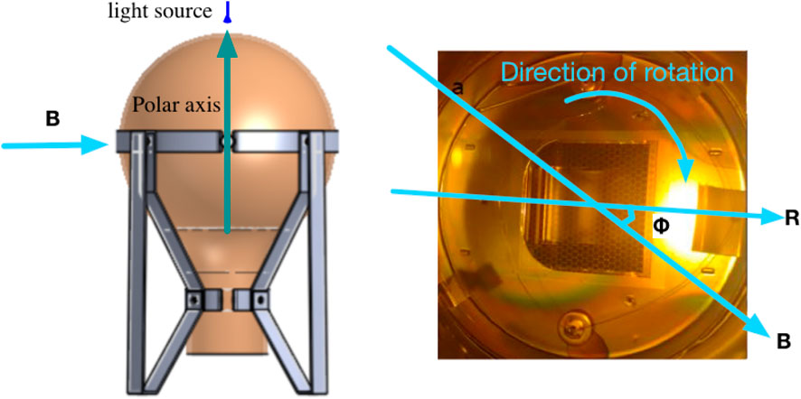
FIGURE 1. Rotation test system. On the left side, the PMT can be rotated around its polar axes while the geomagnetic field and the PMT remain relatively the same. On the right, it is the reference direction of the first dynode.
2.1 The measurement system
The critical parameters to describe the geomagnetic field effects on the PMTs includes the gain, collection efficiency (CE), energy resolution (ER) of the single photoelectron (SPE) spectrum, and the transition time spread (TTS), which is also tested under SPE mode of the PMTs. In this experiment, the incident light is provided by a 405 nm laser diode which has the advantages of a small divergence angle and minimum time delay. The SPE spectrum can be obtained by modifying its light intensity by adjusting the voltage, duty ratio and frequency of the power supply. The spectrum is measured with a Charge-to-Digital Converter (QDC). An event counter is used to calculate the relativity collection efficiency. A time-to-digital converter (TDC) module is used to measure the TTS with a resolution of 35 ps/LSB.
2.2 The rotation device
In the rotation device, the PMT is mounted on a horizontally placed holder, with the polar axis parallel to the vertical plane. Figure 1 (left) is a front view of the set-up. It brings the PMT rotating along its polar axis. When rotating the PMT, the incident light and PMT location keep the same but the dynode direction changes with respect to the local geomagnetic field. The PMT reference direction is shown on the right in Figure 1, denoted as R, is drawn from the center of the arc edge of the focus to the center of the PMT. The angle between the PMT reference direction and the horizontal component of the geomagnetic field B is denoted by ϕ when the PMT rotates clockwise.
In this test system, the emission direction of the photoelectrons does not change relative to the geomagnetic field. However, the relative position of the PMT structure changes when the PMT rotates around its polar axes. Therefore, the output signal varies with the change of the angle ϕ between the reference direction and the local geomagnetic field.
2.3 The revolution device
In a large area PMT, the distance between the photocathode and the first dynode is quite large, and the photoelectron path is strongly affected by the geomagnetic field when it travels from the photocathode to the first dynode. Due to the above effect, the energy and direction of the incident electrons are not uniform anymore. Hence the secondary electron emission coefficient, the gain, as well as the CE, of the PMT vary a lot in different situations. For example, when large area PMTs with the same structure are installed at different positions, the angle of illuminating light and the geomagnetic field will be different, and the photoelectron flying track affected by the geomagnetic will also be different. So a revolution device (shown as Figure 2) is designed to study how the installation position of the PMT contributes to its characteristics in the geomagnetic field.
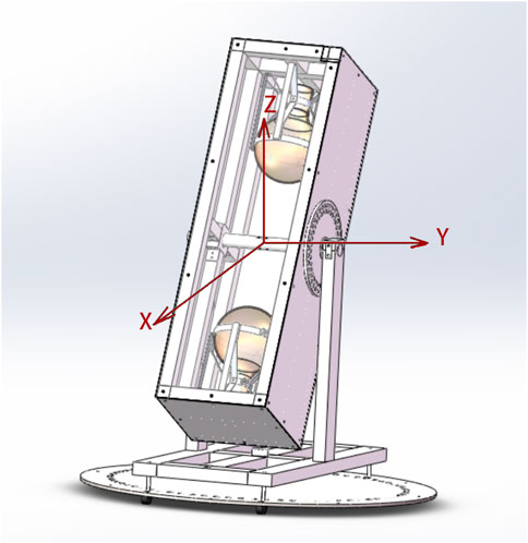
FIGURE 2. Revolution system. This device can bring the PMT rotating around 2π in two plates.
The rotation components were composed of two parts: the dark box which could rotate around 2π in the vertical direction, and a horizontal rotation plate which could rotate around 2π in the horizontal direction below the base. Two 8-inch PMTs can be installed in this device for simultaneous test with point-like light illumination. So in this device, a dark box could bring the PMTs and rotate around 4π manually.
2.4 The shielding of the geomagnetic field
There are two ways to reduce the influence of geomagnetic field on PMT: high permeability permalloy shielding and coil compensation [4,5,12]. In the experiment, permalloy shielding was used to reduce the geomagnetic field effect on PMT with the advantage that the geomagnetic field could be selectively blocked based on the specific influence of different azimuths of the PMT.
The shielding materials were rolled into a cylinder and can cover the entire PMT. The direction of the cylinder is always parallel to the polar axes of the PMT. When the local geomagnetic field is about 38.04 μT, the residual intensity of the geomagnetic field after shielding is reduced to 12.12 μT.
3 The construct factor of the PMT in the geomagnetic field
3.1 The PMT construct contribution
The process of the geomagnetic field effect on photoelectrons in a PMT can be divided into two steps. First, the photoelectron is deviated from the focus by Lorentz force when it travels from the photocathode to the focus, resulting in a decrease in the collection efficiency of the PMT. Secondly, part of the secondary electrons will drift from the effective multiplication area under the action of Lorentz force from the focus to the anode, which will result in the loss of PMT gain [3]. Meanwhile, TTS and ER are also influenced by the geomagnetic field. TTS is affected due to the variation in electron trajectory during travel, which in turn affects the flight time of electrons. ER is affected because the gain of the PMT directly impacts the ER [13].
Considering different properties are related to different parts of the PMT, studies have also been done on the relationship between shielding different parts of the PMT and the performance of the PMT. The relative variation of the performance is given as
FIGURE 3. Geomagnetic effect on different parts of the PMT. 1) no shielding, 2) upper shielding: covering only the region above the PMT equator, 3) lower shielding: covering only the region below the PMT equator, 4) full shielding: covering the entire PMT bulb.
3.2 The dynode structure contribution
The PMT itself, especially dynodes, is not a strict symmetrical geometric structure, resulting in an asymmetric electric field. The directions and values of the total electric and Lorentz forces from the same point are different when PMT rotates around its polar axis.
In the rotation test system, photoelectrons are emitted in the same direction when the PMT rotates around its polar axes since the light is fixed relative to the rotation axes. The PMT properties such as gain, CE, ER and TTS vary while the PMT rotates due to the PMT’s structure asymmetry. Table 1 lists the results of obtained PMT properties with and without shielding. It can be known that PMT’s structure asymmetry has a great contribution to the influence of the geomagnetic field on the PMT performance. The maximum and the minimum relative variation of PMT gain are around +14% at ϕ = 315° and −22% at ϕ = 240° respectively. The maximum and the minimum relative variation of CE are around +20% at ϕ = 90°and −15% at ϕ = 315°. Clearly, the asymmetric design of a PMT cannot be ignored when considering its performance in the magnetic effect.
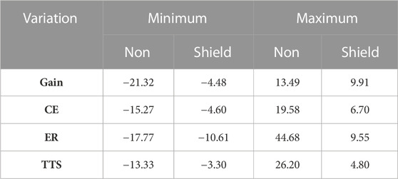
TABLE 1. The maximum, the average and the minimum relative variation [unit: %] of PMT properties with/without shielding when the PMT rotating around its polar axis.
4 The installation position of the PMT in the geomagnetic field
4.1 The affection to the PMT characteristics
In the revolution device, the PMT can be rotated in any plane. Three vectors:
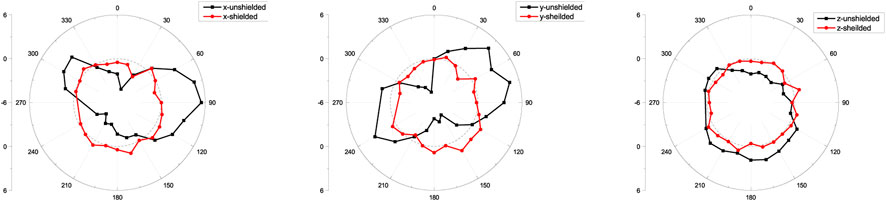
FIGURE 4. Gain variation with the PMT rotating around x, y and z-axes.
4.2 Geomagnetic effect on a sphere surface
The geomagnetic field strength
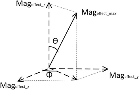
FIGURE 5. The maximum magnetic effects represented by a set of normal coordinates.
The effects of the geomagnetic field distributed around the surface of a sphere can be obtained by resolving the maximum effect into different components in different directions around the surface of the sphere. Eq. 1 is an arbitrary vector of the geomagnetic field effect on the PMT in a fixed direction on the surface of the sphere.
From the data of the revolution system, the geomagnetic effect on the PMT around the surface of a sphere can be induced by Eq. 1. By using this method, the distribution of the effect of the unshielded/shielded geomagnetic field on the gain of the PMT across the entire plane is shown in Figure 6. Within the plane perpendicular to the magnetic field, there are maximum positive and maximum negative effects from the geomagnetic field. The largest relative gain variation is about ±6% without shielding shown on the left of Figure 6. After employing permalloy shielding materials, the largest relative gain variation is about ±2% shown on the right of Figure 6.
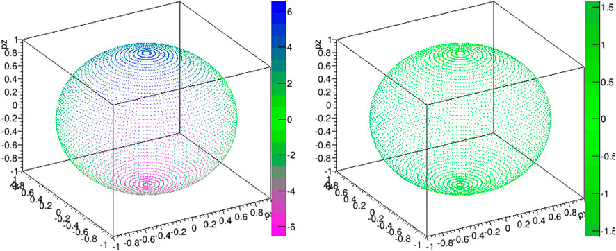
FIGURE 6. Geomagnetic field effects on the property of gain of the PMT. The colour bar represent the relative variation [unit: %].
5 Summary
The geomagnetic effects on the performance of PMTs have been studied with two different test systems: rotation test system and revolution test system. It is found that the asymmetry of the PMT structure is a significant factor in the geomagnetic effect on a PMT, and the PMT can be placed in a specific orientation to reduce the effect caused by asymmetrical structure in the geomagnetic field. The effect of the geomagnetic field on the PMTs varies with its installation direction. By using permalloy shielding, the uniformity of the PMT’s performance can be improved when PMT or its dynode is oriented in different directions.
Data availability statement
The original contributions presented in the study are included in the article/supplementary material, further inquiries can be directed to the corresponding author.
Author contributions
ZF designed the experiment, analyzed the data, and provided the funding. WW and JX performed the experiments. FG and JX analyzed the data and prepared the manuscript. All authors contributed to the article and approved the submitted version.
Funding
The project is supported by Science and Technology Program of Shanghai (Grant No. 22ZC2420700).
Acknowledgments
The authors would like to thank Junqi Xie, assistant physicist at Argonne National Laboratory for his help and suggestions on this work. This work is supported by the PMT Laboratory in IHEP.
Conflict of interest
Author ZF was employed by the China Nuclear Tongchuang (Shanghai) Technology Development Co., Ltd; Author WW was employed by the Huawei Technologies Co., Ltd.
The remaining authors declare that the research was conducted in the absence of any commercial or financial relationships that could be construed as a potential conflict of interest.
Publisher’s note
All claims expressed in this article are solely those of the authors and do not necessarily represent those of their affiliated organizations, or those of the publisher, the editors and the reviewers. Any product that may be evaluated in this article, or claim that may be made by its manufacturer, is not guaranteed or endorsed by the publisher.
References
1. Koblesky T, Roloff J, Polly C, Peng J. Cathode position response of large-area photomultipliers under a magnetic field. Nucl Instr Methods Phys Res Section A: Acc Spectrometers, Detectors Associated Equipment (2012) 670:40–4. doi:10.1016/j.nima.2011.12.054
2.Hamamatsu. Large photocathode area photomultiplier tubes (2023). Available at: https://www.hamamatsu.com/content/dam/hamamatsu-photonics/sites/documents/99_SALES_LIBRARY/etd/LARGE_AREA_PMT_TPMH1376E.pdf (Online; accessed May 16, 2023).
3. Leonora E, Consortium K. Terrestrial magnetic field effects on large photomultipliers. Nucl Instr Methods Phys Res Section A: Acc Spectrometers, Detectors Associated Equipment (2013) 725:148–50. doi:10.1016/j.nima.2012.12.056
4. Calvo E, Cerrada M, Fernandez-Bedoya C, Gil-Botella I, Palomares C, Rodríguez I, et al. Characterization of large-area photomultipliers under low magnetic fields: Design and performance of the magnetic shielding for the double chooz neutrino experiment. Nucl Instr Methods Phys Res Section A: Acc Spectrometers, Detectors Associated Equipment (2010) 621:222–30. doi:10.1016/j.nima.2010.06.009
5. DeVore P, Escontrias D, Koblesky T, Lin C, Liu D, Luk KB, et al. Light-weight flexible magnetic shields for large-aperture photomultiplier tubes. Nucl Instr Methods Phys Res Section A: Acc Spectrometers, Detectors Associated Equipment (2014) 737:222–8. doi:10.1016/j.nima.2013.11.024
6. Abusleme A, Adam T. JUNO physics and Detector. Prog Part Nucl Phys (2021) 123:103927. doi:10.1016/j.ppnp.2021.103927
7.Hamamatsu. R12860 (2023). Available at: https://www.hamamatsu.com/eu/en/product/optical-sensors/pmt/pmt_tube-alone/head-on-type/R12860.html (Online; accessed May 16, 2023).
8. Wang Y, Qian S, Zhao T, Tian J, Li H, Cao J, et al. A new design of large area mcp-pmt for the next generation neutrino experiment. Nucl Instr Methods Phys Res Section A: Acc Spectrometers, Detectors Associated Equipment (2012) 695:113–7. doi:10.1016/j.nima.2011.12.085
9.Hamamatsu. R5912 (2023). Available at: http://pdf.datasheetcatalog.com/datasheet/hamamatsu/R5912.pdf (Online; accessed May 16, 2023).
10. Abeysekara A, Alfaro R, Alvarez C, Álvarez J, Arceo R, Arteaga-Velázquez J, et al. The hawc gamma-ray observatory: Design, calibration, and operation, 33rd International Cosmic Ray Conference, Rio de Janeiro, Brazil (2013). arXiv preprint arXiv:1310.0074.
11. Caldwell T, Seibert S, Jaditz S. Characterization of the r5912-02 mod photomultiplier tube at cryogenic temperatures. J Instrumentation (2013) 8:C09004. doi:10.1088/1748-0221/8/09/c09004
12. Ghazikhanian V, McDonald KT. μ-metal wire magnetic shields for large pmts (2007). Available at: https://www.researchgate.net/publication/268259966_m-Metal_Wire_Magnetic_Shields_for_Large_PMTs.
Keywords: large area PMT, geomagnetic field effect, shielding, dynode structure, R5912
Citation: Fu Z, Gao F, Wang W and Xia J (2023) Geomagnetic field effects on the performance of 8-inch dynode photomultiplier tubes. Front. Phys. 11:1160388. doi: 10.3389/fphy.2023.1160388
Received: 07 February 2023; Accepted: 06 June 2023;
Published: 15 June 2023.
Edited by:
Qian Sen, Chinese Academy of Sciences (CAS), ChinaReviewed by:
Jifeng Han, Sichuan University, ChinaWenjie Wu, University of California, Irvine, United States
Yasuhiro Nishimura, Keio University, Japan
Copyright © 2023 Fu, Gao, Wang and Xia. This is an open-access article distributed under the terms of the Creative Commons Attribution License (CC BY). The use, distribution or reproduction in other forums is permitted, provided the original author(s) and the copyright owner(s) are credited and that the original publication in this journal is cited, in accordance with accepted academic practice. No use, distribution or reproduction is permitted which does not comply with these terms.
*Correspondence: Jingkai Xia, eGlhamtAc2hhbmdoYWl0ZWNoLmVkdS5jbg==