 Xinxiang Miao1†
 Guorui Zhou1†
 Jiaxuan Chen2*Qihua Zhu1*
 Yuhai Li2Xiaodong Jiang1Haibing Lv1Caizhen Yao1Yilan Jiang1Longfei Niu1
 Siheng Xiang1
- 1Laser Fusion Research Center, China Academy of Engineering Physics, Mianyang, China
- 2Center for Precision Engineering, Harbin Institute of Technology, Harbin, China
Introduction: Based on microfibers with sol–gel film, this study focuses on developing an organic contaminant sensing device to monitor airborne organic contamination in high-power laser facilities.
Methods: The device heightened the sensitivity to the external environment with the nano-structure of sol–gel on the microfiber surface. The relationship between the additional laser transmission power loss caused by contaminants and the filling rate of the porosity of the film was discussed. In addition, we obtained the relationship between the additional loss and the refractive index of the microstructure.
Results: The experimental results indicated that employing microfibers with microstructure coating could significantly improve sensing sensitivity to airborne organic contaminants. The precision of sensing surface contaminants can reach ng/cm2. When the concentration of organic contaminants is lower than 7.5%, the adsorption process of the microstructure coating is dominated by single-molecule adsorption, and the additional loss increases exponentially with increasing concentration, while the sensing limit is 70 ppm. When the concentration of organic contaminants exceeds 7.5%, the adsorption process of the surface microstructure coating is dominated by multimolecular adsorption. Therefore, the additional loss is exponentially related to the concentration of airborne organic contaminants, while the sensing limit is 10 ppm.
Discussion: The study explored the adsorption mechanism of the sol–gel film to airborne organic contaminants at different concentrations. The Langmuir monolayer adsorption isotherm model and the Freundlich multi-molecular layer adsorption isotherm model was adopted to analyze and verify the experimental results, which suggested that the experimental results agree well with the simulation results. This work can be considered for in situ monitoring of airborne concentration contaminants and the transmittance of optics with the sol–gel film, and it also provides a new research method for in situ monitoring of airborne organic contaminants in the vacuum environment.
1 Introduction
With continuous research on high-power laser technology, especially the development of inertial confinement fusion (ICF) systems, the power density of each component in the optical system is increasing, especially more than 1.9 MJ in the National Ignition Facility (NIF) [1–3]. Since the 1980s, Lawrence Livermore National Laboratory (LLNL) has reported a series of optical component damage disasters caused by a large amount of contamination in Nova and Beamlet systems. Recently, hundreds of damage spots have been observed on optics under the irradiation of several shots at 8 J/cm2. Some of these damage spots were caused by particles and organic contaminants, which can also be found in preprocessed fused silica optics (the advanced mitigation process, AMP3) and the closed vacuum environment [4–6]. Scholars have made great efforts to control the clean environment in the high-power laser facility. In the stage of laser design, each key unit module of lasers is designed as a sealed system to prevent the entry of external contaminations [7–9].
During the operation of the laser facility, there are always non-volatile residual organic contaminants at the molecular level on the surface of optical and mechanical components due to incomplete cleaning or contamination introduced in the assembly process [10]. Such organic contaminants volatilize in the vacuum or stray light and exist in the vacuum environment as molecules [11]. Unfortunately, in this vacuum environment, quarter-wave porous silica antireflection coatings prepared by the sol–gel process have been performed on transmissive components [11, 12]. Due to the porous structure of the antireflection film, it tends to adsorb organic contaminants in the vacuum environment [13]. When organic contaminants are adsorbed on the optical surface, the refractive index of the antireflective film will change. It can cause a decrease in the optical surface transmittance, an increase in the total optical loss, and even a serious reduction of the damage resistance ability of the optical surface [14, 15]. Therefore, monitoring and controlling molecular organic contaminants is one of the important conditions for obtaining a stable output of the high-power laser system. Tovena et al. [16, 17] analyzed the organic contaminants on the optical surface of the LIL faculty by referring to the outgassing rate of nearby materials, and the source of the contaminants on the optical surface was obtained. Based on the experiment results, it was found that such contaminants had a serious impact on the damage resistance ability of the optical surface [18]. The researchers of the LLNL proposed to adopt a surface acoustic wave sensor (SAW) to detect organic contaminants in vacuum [19, 20]. A large surface area (several square millimeters) and a high requirement for lithography technology were required. A quartz crystal microbalance (QCM) used in the aerospace field could measure micro-mass, and the range of measurable deposited mass due to contaminants spans from ng/cm2 to hundreds of ug/cm2 [21]. However, it was limited by resonance frequency, and its theoretical detection accuracy could reach the order of nanograms.
Based on the strong confinement ability and evanescent field characteristics of micro-nano optical fibers (MNOFs) [22, 23], a new method of molecular organic contaminant sensor using a micro-nano optical fiber with surface microstructures was proposed [24]. We have developed many kinds of microstructures to improve the sensing sensitivity of MNOFs and to realize the monitoring of airborne organic contaminations in a vacuum environment [25–27]. However, although the amount of molecular organic contaminants on the surface of optics within the sol–gel film is closely related to the amount of airborne organic contaminations in the same environment, there are also significant differences. There is an urgent requirement for developing sensing technology that can directly respond to surface organic contaminants.
In this work, we prepared MNOFs with the same thickness of the sol–gel film on the surface to ensure the consistency of the absorption capacity of molecular organic contaminants with the optical component. Then, the effective refractive index of the sensing waveguide was changed, resulting in a change in its output characteristics. The physical model of the sensor unit was established and demonstrated by experiments. The sensitivity to organic contaminants absorbed by the sol–gel film of MNOFs in vacuum is obtained as the transmittance of an optical component in the same environment. Therefore, the additional loss change of surface organic contaminant concentration was obtained in this study.
2 Theoretical model
The surface microstructures of MNOFs are obtained by coating sol–gel films, which have a porous structure, as shown in Figure 1. When molecular organic contaminants exist in the surrounding environment, they are adsorbed in the sol–gel film on the MNOF surface in an embedded manner. The change in the refractive index of the coated film is caused by the absorption of contaminants. When the refractive index changes from the surface microstructure adsorbing contaminants on the surface of optical fibers, light will begin to leak out to the outside of the optical fibers, resulting in the attenuation of the transmission power of MNOFs [22]. The concentration of organic contaminants can be obtained by monitoring the change in the optical power of MNOFs.
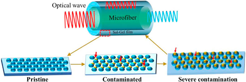
FIGURE 1. Structure of the microfiber and the principle of contaminants adhered to the microfiber with the sol–gel film.
According to the large evanescent wave characteristics of MNOFs, the main factor affecting the sensitivity of MNOFs is the adsorption of contaminants on the surface of sol–gel thin films when the size of MNOFs is fixed. The refractive index of sol–gel films is mainly determined by the porosity of the films. Therefore, the refractive index of sol–gel films after adsorbing contaminants is studied using the mixed-medium correlation model [27–30]. Sol–gel films are regarded as a mixed medium of silicon dioxide and air. In the mixed medium, the dielectric constant of the film satisfies the following relationship, as shown in Eq. 1 [27, 28]:
where
where
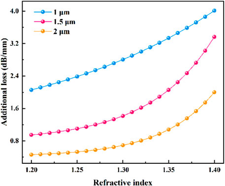
FIGURE 2. Relationship between the additional loss and the refractive index of the thin film on MNOFs.
3 Experiment
Fabrication of MNOFs: the MNOF fabrication setup was built using an electric heater and step motor translations with programming functions [31]. The common single-mode communication fiber (SMF-28, Corning) was heated to the melting point at high temperatures. At the same time, a program was written to control the coordinated movement of motors to pull the fiber into MNOFs with diameter of a micron and length of a centimeter. The diameter, shape, and length of MNOFs can be controlled accurately under the condition of parameters such as heating temperature, drawing speed, and heating area.
A high-precision measurement platform for contaminant sensors was built using amplification and phase-locked technology. The light source was a DFB laser with a center wavelength of 1,550 nm. To further improve the measurement accuracy, the source light was divided into two paths by a fiber coupler. One was used as signal light, and the other was selected as reference light, as shown in Figure 3. It eliminated the measurement error caused by the power disturbance of the light source. In the experiment, the sensing unit was transferred into an environment with organic contaminants, and the measured signal data were transmitted to a computer. A software package monitored the change of additional loss of the sensing unit, and the corresponding relationship between the concentration of organic contaminants and the additional loss was obtained.
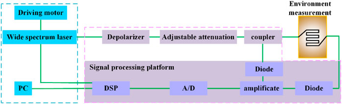
FIGURE 3. Schematic diagram of the experimental setup for contaminant sensor.
4 Results and discussion
4.1 Sample fabrication
MNOFs with different diameters were fabricated using an MNOF fabrication setup. The morphology of the fabricated MNOFs is shown in Figure 4. The fabricated MNOFs have smooth waist surfaces and good diameter uniformity, which can meet the requirements of the sensing unit.
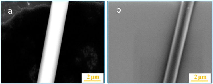
FIGURE 4. SEM images of MNOF diameter with (A) 2.5 μm and (B) 1.5 μm.
A porous chemical film with microstructure is formed on the surface of the fabricated MNOFs by dip-coating in the silica sol–gel synthesized by hydrolysis and condensation of tetraethyl orthosilicate (TEOS) in the ethanol solvents with a base catalyst. The MNOFs were dipped into the sol–gel solution with a 3% concentration for at least 1 min and permeated totally. The thickness of the microstructure can be controlled by the pulling rate and the concentration of the sol–gel solution [32]. To enhance the mechanical properties of the microstructure film, the ammonia treatment method was adopted to post-treat the samples. The morphologies of the sol–gel film on the MNOFs and the optics surfaces with the same thickness are shown in Figure 5. The surface roughness of the optical components is the same as that of the optical fiber surface, which is about 20 nm. This ensures that both surfaces have the same adsorption properties. The porous film adhered to the surface of MNOFs in a uniform state possesses good mechanical properties.
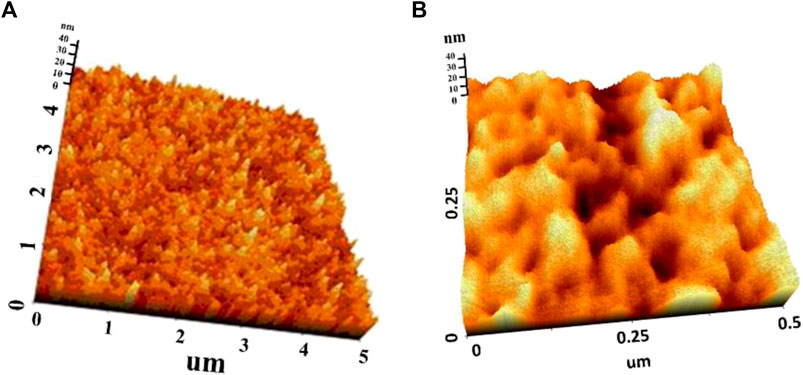
FIGURE 5. AFM patterns of the surface morphologies of (A) sol–gel film on the optics surface; (B) MNOFs with the sol–gel film.
4.2 Adsorption performance analysis
To verify the different responses of bare MNOFs and MNOFs with the microstructure film to molecular organic contaminants, various sensing units with the same diameter placed in a vacuum chamber were connected to two independent channels of the high-precision measuring platform. The vacuum chamber was placed into an ISO 5 clean environment, with a temperature of 20°C ± 0.3 and humidity of 40% ± 3. The source of organic contaminants was placed in the chamber, and the response of the sensing unit was monitored in situ by the written program. The experimental results are shown in Figure 6. It can be seen that the additional loss of bare MNOFs is 0.01 dB, while that of MNOFs with the sol–gel film is about 0.14 dB. The sensitivity of MNOFs with the microstructure film is far higher than that of bare MNOFs. The additional loss of MNOFs with the sol–gel film adsorbing molecular contaminants shows a linear upward trend. Therefore, the enrichment ability of MNOFs with the microstructure film for organic contaminants is much higher than that of bare MNOFs. Fabrication of the microstructure on the surface of MNOFs is one of the important means to improve the sensitivity of the sensing units.
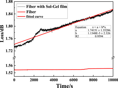
FIGURE 6. Experimental results of MNOFs and MNOFs with sol–gel film sensing units.
4.3 Sensing performance
The sensing units were placed into certain concentrations of airborne organic contaminants, and the experimental data were collected every second by the software to monitor the additional losses and changes caused by increasing concentrations of airborne organic contaminants. Different concentrations of airborne organic contaminants were obtained by heating dibutyl phthalate (DBP) [27]. After the sensing process, the sensing units were placed into the alcohol solution to clean organic contaminants adhered to the sol–gel film of MNOFs, and the measurement results were saved, as shown in Figure 7. The experimental results are divided into four stages. For the first stage, as shown in Figure 7A, the sensing unit is placed into the same ISO 5 clean environment, which only installed the particle filters, but no AMC filters. With the internal static condition, the particle number of 0.3 um is approximately 0. The additional loss with 0.67 dB does not increase significantly, indicating fewer airborne organic contaminants. When the sensing unit is placed into a certain concentration of airborne organic contaminants, the sol–gel film on the surface of MNOFs begins to adsorb a number of organic contaminants in the environment, and the additional loss increases sharply, showing the exponential trend, as shown in the second stage. At the initial stage of adsorption, the additional loss increases rapidly by 1.3 dB, as shown in Figure 7B. The trend of change shows that Langmuir monolayer adsorption occurred on the surface of MNOFs [33, 34]. With the adsorption of organic contaminants by the first monolayer of the thin film approaching equilibrium, the rate of the additional loss changes decreases gradually, as shown in the third stage. Figure 7C illustrates the BET multi-molecular layer adsorption on the surface, which conforms to the IV isotherm, indicating the existence of mesoporous adsorption in the sol–gel film [35]. The additional loss changes from 0.67 dB to 1.63 dB during the process of adsorption. Subsequently, the sensing units are put into an alcohol solution, and the contaminants adhered to the sol–gel film are desorbed. The additional loss decreases sharply and restores to about 1.0 dB. When the rate of the additional loss decrease slows down, the sensing units are disturbed slightly in an alcohol solution, and the desorption rate of the sensing units increases significantly. Finally, the additional loss recovers to the initial loss of about 0.67 dB, as shown in the fourth stage (Figure 7D). The experimental results reveal that the number of organic contaminants can be obtained based on the simulation results and the additional loss of continuous monitoring. Figure 7D shows that the sensing units can be restored to the initial state by alcohol cleaning, which proves that the microstructure film has good reusability. However, after 20 times of cleaning, the additional losses increase sharply, and the microstructure film is seriously damaged [23].
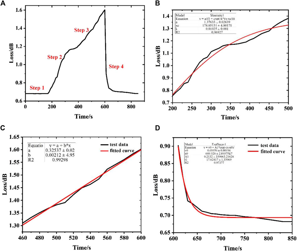
FIGURE 7. Evolution of the additional loss of the sensing units during the process of contaminant sensing; (A) all process of contaminant sensing; (B) step 2: the initial stage of adsorption; (C) step 3: the second stage of adsorption; (D) step 4: the sensing unit dipped into the alcohol solution.
4.4 Physical sensing mechanism
The sensing unit with a diameter of 1.5 μm and a waist length of 10 mm is placed into airborne contaminants of different concentrations. The evolution of additional loss is monitored in situ, and the relationship between the change of additional loss and the concentration of organic contaminants is discussed, as shown in Figure 8. At the same time, the whole sensing process is divided into two stages according to the growth rate. When the sensing unit is immersed in 2.4% airborne contaminants, the additional loss is 0.0003 dB. The additional loss shows an exponential growth trend with increased organic contaminant concentration, and the fitting function is y = 0.001*exp (x/0.03)-0.0022. When the concentration of contaminants exceeds 7.5%, the relationship between the additional loss and the concentration of contaminants shows a faster exponential growth trend. Its growth trend is slightly different from that of low concentration.
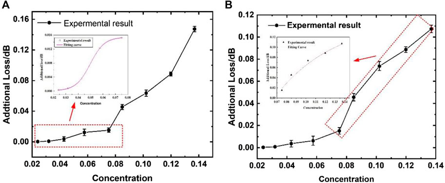
FIGURE 8. Sensing results at different concentrations of contaminants; (A) the concentration less than 7.5%; (B) the concentration more than 7.5%.
Based on verification and analysis of the results, the additional loss increases exponentially with the concentration of airborne contaminants at a low concentration, and the detecting limit is about 10 ppm. However, the additional loss has a fast exponential relationship with the concentration of airborne contaminants at high concentrations, and the detecting limit is about 70 ppm.
The adsorption of the microstructure film on the MNOF surface is dominated by single-molecule adsorption at a concentration of less than 7.5% [33]. The additional loss is approximately low exponential with the concentration of contaminants. Thus, the concentration of contaminants can be deduced by the change of the additional loss monitored. The adsorption of the microstructure film on the surface of MNOFs is dominated by multi-molecular adsorption at a concentration of more than 7.5% [34]. Because of the difference in the adsorption mechanism in the microstructure film on the MNOF surface at the lower (<7.5%) and the higher (>7.5%) concentration of contaminants, the additional loss caused by the unit refractive index change is nonlinear according to the calculation results in Figure 2. Thus, the detection limit is about 10 ppm at a concentration of less than 7.5% and about 70 ppm at a concentration of more than 7.5%. Figure 9 illustrates the relationship between airborne organic concentration, refractive index, and transmittance of large-aperture optical components. The refractive index of the chemical film on the surface of the optical component directly affects the transmittance, and there is a linear relationship between the refractive index and the transmittance [28]. The concentration of airborne organic contamination affects the refractive index of the MNOFs’ surface sol–gel film. The thickness and microstructure of the MNOFs’ surface sol–gel film and the sol–gel film on the surface of the optical components are the same. Thus, the evolution of optical component transmittance can be reflected by the MNOFs through the change of the refractive index, manifested as the loss increase. However, MNOFs have an ultra-small sensitive area compared to other sensors (such as QCM) and is suitable for measuring spatially uniformly distributed organic contaminants. In another case, it can be solved by increasing the number of MNOFs. Due to their ultra-thin diameter, MNOFs are susceptible to external environmental factors (e.g., strong air flow and vibration) during preparation, packaging, and sensing processes. However, MNOF sensors can also be extended to monitor organic contaminants in laser faculties due to the high-quality environment.
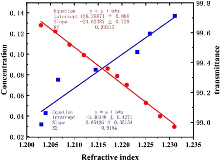
FIGURE 9. Response of the refractive index and the transmittance under different concentrations.
5 Conclusion
Based on the fabrication of MNOF sensors, 70-nm sol–gel films were prepared on the surface of MNOFs by the dip-coating process to enhance the sensitivity of the sensing units. The change of additional loss caused by contaminants adhered to the sol–gel film on the surface of MNOFs was analyzed by the FDTD method. The results illustrated that the evanescent field of the sensing units changed when airborne organic contaminants were adsorbed on the surface of MNOFs. In the experiments, the MNOFs with 1.5 μm diameter were selected, and the experimental setup was established to measure the concentration of airborne organic contaminants. The experimental results revealed that the sensitivity of the sensing units increased by 14 times by fabricating the microstructure film on the surface of MNOFs. The adsorption of the sol–gel film on the surface of MNOFs was dominated by single-molecule adsorption at a concentration of less than 7.5%. The additional loss shows exponential growth trend with the increasing concentration of contaminants. The relationship between the additional loss and the concentration of organic contaminants can be obtained by the modification function. The experimental results agree with the theoretical calculation. The contaminant sensors can be considered for monitoring the concentration of airborne contaminants and the transmittance of large-aperture optics with sol–gel in high-power laser faculties.
Data availability statement
The original contributions presented in the study are included in the article/Supplementary Material, further inquiries can be directed to the corresponding authors.
Author contributions
Conceptualization and formal analysis: XM and GZ; writing—review and editing: JC and QZ; methodology: XJ; formal analysis: HL; data curation: CY; writing—original draft preparation: YJ and YL; software: LN; validation: SX. All authors contributed to the article and approved the submitted version.
Funding
This research was funded by the National Natural Science Foundation of China, Grant Numbers 61705205, 51535003, and 12174355.
Conflict of interest
The authors declare that the research was conducted in the absence of any commercial or financial relationships that could be construed as a potential conflict of interest.
Publisher’s note
All claims expressed in this article are solely those of the authors and do not necessarily represent those of their affiliated organizations, or those of the publisher, the editors, and the reviewers. Any product that may be evaluated in this article, or claim that may be made by its manufacturer, is not guaranteed or endorsed by the publisher.
References
1. Bishop B. National Ignition Facility experiment puts researchers at threshold of fusion ignition (2021). California: Lawrence Livermore National Laboratory.
2. Zylstra AB, Hurricane OA, Callahan DA, Kritcher AL, Ralph JE, Robey HF, et al. Burning plasma achieved in inertial fusion. Nature (2022) 601:542–8. doi:10.1038/s41586-021-04281-w
3. Betti R, Hurricane OA. Inertial-confinement fusion with lasers. Nat Phys (2016) 12:435–48. doi:10.1038/nphys3736
4. Bude J, Carr CW, Miller PE, Parham T, Whitman P, Monticelli M, et al. Particle damage sources for fused silica optics and their mitigation on high energy laser systems. Opt Express (2017) 25:11414–35. doi:10.1364/oe.25.011414
5. Ling X, Liu S. Laser-induced thermal damage simulations of optical coatings due to intercoupling of defect and organic contamination. IEEE Photon J (2018) 10:1–7. doi:10.1109/jphot.2018.2848619
6. Baxamusa S, Miller PE, Wong L, Steele R, Shen N, Bude J. Mitigation of organic laser damage precursors from chemical processing of fused silica. Opt Express (2014) 22:29568–77. doi:10.1364/oe.22.029568
7. Genin FY, Feit MD, Kozlowski MR, Rubenchik AM, Salleo A, Yoshiyama J. Rear-surface laser damage on 355-nm silica optics owing to Fresnel diffraction on front-surface contamination particles. Appl Opt (2000) 39:3654–63. doi:10.1364/ao.39.003654
8. Genin FY, Sheehan LM, Yoshiyama JM. Statistical study of UV-laser-induced failure of fused silica. Laser-Induced Damage Opt Mater SPIE (1998) 3244:155–63.
9. Fong MC, Lee AL. Analytical model for predicting molecular deposition on optical surfaces. Opt Syst Contam Effects, Meas Control SPIE (1992) 1754:238–48.
10. Pryatel JA, Gourdin WH, Frieders SC. Cleaning practices and facilities for the national ignition facility (NIF). Laser-Induced Damage Opt Mater SPIE (2014) 9237:390–410. doi:10.1117/12.2075927
11. Thomas IM, Burnham AK, Ertel JR. Method for reducing the effect of environmental contamination of sol-gel optical coatings. Proceedings of the 3rd Int Conf Solid State Lasers Appl Inertial Confinement Fusion SPIE (1999) July 1999, Monterey, CA,3492:220–9.
12. Thomas IM. High laser damage threshold porous silica antireflective coating. Appl Opt (1986) 25:1481–3. doi:10.1364/ao.25.001481
13. Li Y, Bai Q, Guan Y, Zhang P, Shen R, Lu L. In situ plasma cleaning of large-aperture optical components in ICF. Nucl Fusion (2022) 62:076023. doi:10.1088/1741-4326/ac555c
14. Pareek R, Kumbhare MN, Mukherjee C. Effect of oil vapor contamination on the performance of porous silica sol-gel antireflection-coated optics in vacuum spatial filters of high-power neodymium glass laser. Opt Eng (2008) 47:023801. doi:10.1117/1.2844551
15. Wang X, Shen J. A review of contamination-resistant antireflective sol–gel coatings. J Sol-gel Sci Technol (2012) 61:206–12. doi:10.1007/s10971-011-2615-4
16. Guéhenneux G, Veillerot M, Tovena I. Evaluation of the airborne molecular contamination inside the LIL. Nucl Instrum Methods Phys Res A (2006) 557:676–83. doi:10.1016/j.nima.2005.11.116
17. Bien-Aimé K, Néauport J, Tovena-Pecault I, Fargin E, Labrugère C, Belin C, et al. Laser induced damage of fused silica polished optics due to a droplet forming organic contaminant. Appl Opt (2009) 48:2228–35. doi:10.1364/ao.48.002228
18. Bien-Aimé K, Belin C, Gallais L, Grua P, Fargin E, Néauport J, et al. Impact of storage induced outgassing organic contamination on laser induced damage of silica optics at 351 nm. Opt Express (2009) 17:18703–13. doi:10.1364/oe.17.018703
19. Wegner PJ, Auerbach JM, Biesiada TA. NIF final optics system: Frequency conversion and beam conditioning. Opt Eng Lawrence Livermore Natl Lab Natl Ignition Facility SPIE (2004) 5341:180–9. doi:10.1117/12.538481
20. Ho CK, Lindgren ER, Rawlinson KS, McGrath L, Wright J. Development of a surface acoustic wave sensor for in-situ monitoring of volatile organic compounds. Sensors (2003) 3:236–47. doi:10.3390/s30700236
21. Dirri F, Palomba E, Longobardo A, Zampetti E, Saggin B, Scaccabarozzi D. A review of quartz crystal microbalances for space applications. Sensors Actuators A: Phys (2019) 287:48–75. doi:10.1016/j.sna.2018.12.035
22. Tong L, Lou J, Mazur E. Single-mode guiding properties of subwavelength-diameter silica and silicon wire waveguides. Opt Express (2004) 12:1025–35. doi:10.1364/opex.12.001025
23. Zeng X, Wu Y, Hou C, Bai J, Yang G. A temperature sensor based on optical microfiber knot resonator. Opt Commun (2009) 282:3817–9. doi:10.1016/j.optcom.2009.05.079
24. Zhou GR, Lv HB, Yuan XD, Zhou H, Liu H, Li KX, et al. Liquid concentration sensing properties of microfibers with a nanoscale-structured film. Chin Phys Lett (2015) 32:034202. doi:10.1088/0256-307x/32/3/034202
25. Niu LF, Zhou GR, Miao XX, Yuan X, Kumar R, Liu H, et al. Micro/nanofiber with hollow silica nanoparticles thin-film for airborne molecular contaminants real-time sensing. Adv Condensed Matter Phys (2018) 2018:1–6. doi:10.1155/2018/4950787
26. Zhou GR, Niu LF, Jiang YL, Liu H, Xie X, Yan H, et al. Sensing of airborne molecular contaminants based on microfiber coupler with mesoporous silica coating. Sensors Actuators A: Phys (2019) 287:1–7. doi:10.1016/j.sna.2018.12.046
27. Zhou GR, Xiang SH, You H, Niu L, Jiang Y, et al. A novel airborne molecular contaminants sensor based on sagnac microfiber structure. Sensors (2022) 22:1520. doi:10.3390/s22041520
28. Born M, Wolf E. Electromagnetic potentials and polarization. In: AB Bhatia, and PC Clemmow, editors. Principles of optics. New York: Pergamon Press (1980). p. 87.
29. Brinker CJ, Hurd AJ, Schunk PR, Frye G, Ashley C. Review of sol-gel thin film formation. J Non-Crystalline Sol (1992) 147:424–36. doi:10.1016/s0022-3093(05)80653-2
30. Vorotilov K, Petrovsky V, Vasiljev V. Spin coating process of sol-gel silicate films deposition: Effect of spin speed and processing temperature. J Sol-Gel Sci Technol (1995) 5:173–83. doi:10.1007/bf00487014
31. Wei ZT. The evanescence character of optical microfiber and research on micropollutant detection. Changsha: Ph. D, National University of Defense Technology (2013).
32. Huang L, Yan H, Yan L, Liu T, Zhang Z, Yang K, et al. Improvement of the environmental stability of sol-gel silica anti-reflection coatings. J Sol-Gel Sci Technol (2022) 101:630–6. doi:10.1007/s10971-022-05725-z
33. Brunauer S, Deming LS, Deming WE, Teller E. On a theory of the van der Waals adsorption of gases. J Am Chem Soc (1940) 62:1723–32. doi:10.1021/ja01864a025
34. Ferguson JB. The equilibrium between carbon monoxide, carbon dioxide, sulfur dioxide and free sulfur. J Am Chem Soc (1918) 40:1626–44. doi:10.1021/ja02244a003
Keywords: microfiber, airborne organic contaminants, sol–gel film, environment monitoring, adsorption mechanism
Citation: Miao X, Zhou G, Chen J, Zhu Q, Li Y, Jiang X, Lv H, Yao C, Jiang Y, Niu L and Xiang S (2023) Characterization of an airborne organic contaminant sensor based on microfibers with sol–gel film. Front. Phys. 11:1164297. doi: 10.3389/fphy.2023.1164297
Received: 12 February 2023; Accepted: 12 July 2023;
Published: 28 July 2023.
Edited by:
Gopala Krishna Podagatlapalli, Gandhi Institute of Technology and Management (GITAM), IndiaReviewed by:
Pablo Cencillo-Abad, University of Central Florida, United StatesJin Li, Northwest A&F University, China
Copyright © 2023 Miao, Zhou, Chen, Zhu, Li, Jiang, Lv, Yao, Jiang, Niu and Xiang. This is an open-access article distributed under the terms of the Creative Commons Attribution License (CC BY). The use, distribution or reproduction in other forums is permitted, provided the original author(s) and the copyright owner(s) are credited and that the original publication in this journal is cited, in accordance with accepted academic practice. No use, distribution or reproduction is permitted which does not comply with these terms.
*Correspondence: Jiaxuan Chen, Y2hlbmppYXh1YW5AaGl0LmVkdS5jbg==; Qihua Zhu, cWloemhAMTYzLmNvbQ==
†These authors have contributed equally to this work