 Marija Gajevic Joksimovic
 Jeanette Hussong
 Ilia V. Roisman
- Institute for Fluid Mechanics and Aerodynamics, Technische Universität Darmstadt, Darmstadt, Germany
Spray cooling of solid substrates is one of the methods used in various industrial processes such as forging, quenching or other metallurgical applications, electronics, pharmaceutical industry, medicine, or for cooling of powerful electrical devices. Spray cooling is governed by various hydrodynamic and thermodynamic processes, like drop impact, heat conduction in the substrate and convection in the spreading drops, and different regimes of boiling. The problem of modeling spray cooling becomes even more challenging if the liquid is multicomponent. The presence of components with various physicochemical properties (surfactants, binders, dispersed particles, etc.) can significantly affect the entire process of spray impact, as well as the outcome of the known cooling regimes and could lead to a formation of a thin deposited layer on the substrate. In this experimental study, spray impact onto a substrate, initially heated to temperatures significantly exceeding the liquid saturation point, is visualized using a high-speed video system. The heat transfer associated with spray impact is characterized using an array of thermocouples installed in a thick metal target. As a working fluid, a mixture of a distilled water and industrial white lubricant was used. It is observed that the presence of very small concentrations of lubricant augments the heat flux dramatically, particularly at high wall temperatures, at which usually film boiling is observed for spray cooling by using distilled water. Three main mechanisms lead to the increase of heat flux and shift of the Leidenfrost point. They are caused by the significant viscosity increase of the evaporating lubricant solutions, by an increase of the substrate wettability and by the emergence of stable liquid sheets between bubbles, preventing their coalescence and percolation of the vapor channels.
1 Introduction
A spray impacting onto a heated surface is found in a broad range of industrial processes. These include, among others, wall impact of a fuel spray in engines [1,2] or gas turbines, in selective catalytic reduction (SCR) systems of diesel driven vehicles [3] as well as in a multitude of other systems. Spray-induced cooling is extensively used during die forging, hot mill rolling [4], cooling of power electronics [5], etc. An extensive overview of spray cooling technology, with water or other one-component liquids being used as a working fluid can be found in [6–11]. For moderate temperatures that do not exceed the saturation temperature, the cooling is realized mainly through the impact of single drops [12], convection in a thin liquid wall film and through the evaporation at the free surfaces of the liquid layer. The cooling is enhanced significantly on structured substrates due to the local cooling in the neighborhood of the contact lines [13–15].
At higher wall temperatures, the phenomena are accompanied by boiling and is influenced significantly by the corresponding thermodynamic phenomena. Different regimes have been observed during spray cooling at various wall temperatures and impact parameters. These regimes include the nucleate boiling regime [9,16], characterized by the heterogeneous nucleation of multiple bubbles on the wetted part of the solid surface; the transition regime, when the substrate surface is not uniformly wetted due to the percolation of the vapor in channels formed by the coalescence of the bubbles [17]; the film boiling regime [10,18,19], characterized by the complete rebound of the impacting drops; and the thermal atomization regime, accompanied by the generation of an intensive flow of fine secondary drops [20] in the case of high impact velocities of the primary drops. In order to simplify physical modeling of the associated thermal-hydraulic phenomena, a spray can be approximated as an aggregate of individual dispersed droplets, which means that mechanisms governing the impact of individual drops onto a heated surface need to be well understood as well [18].
In most cases, experiments are performed using pure liquids, with distilled water as the most commonly used liquid. However, quite recently, application of complex, multi-component liquids for the enhancement of spray cooling started to attract increased attention. As a result, spraying fluids often represent a multi-component mixture of water and lubricants and perform not only a role in cooling, but also in lubrication, for example, in cooling of dies or mechanical parts in the forging industry. Such industry level liquids, suspensions, emulsions and solutions, are designed not only to cool, but also to reduce wear and friction. In [21], an optimal concentration of the surfactants has been determined experimentally for sprays at temperatures below the boiling point. It is known that at higher wall temperatures, the addition of surfactants can significantly influence the phenomena of boiling, causing foaming in the near-wall region and thus enhancing spray cooling [22–27]. Additionally, surfactants can potentially cause the delay of the Leidenfrost point, as already reported in [28,29]. Moreover, the heat transfer can be influenced by the dissolution of different types of organic salts in the bulk liquid [30,31]. For example, [32], have noted that the heat flux at the surface of the very hot metal substrates at 900°C significantly increases by the addition of the dissolved salts in water used for cooling. Use of salt water for spray cooling produces a higher heat removal rate because of the dominance of salt deposition phenomenon, as shown in [33]. Even at relatively low temperatures for spray cooling, at 240°C, the addition of salts reduced the time required for cooling by an order of magnitude, as shown in [34]. Moreover, it has been discovered that salt solutions increase Leidenfrost point [35,36].
Heat flux can be enhanced by the addition of a certain amount of a polymer [37,38]. An optimum polymer concentration can be determined experimentally for a maximum heat flux.
Emulsions can also be useful for metal quenching if the formation of a solid deposition layer is not desirable. Experiments show, that using emulsions as the cooling liquids can potentially influence the heat flux. In [39] it was shown that the heat flux provided by an oil-in-water emulsion is lower than that of pure water at the same temperatures while using kerosene-based emulsions enhances cooling during the quenching process. It is interesting that using oil-in-water emulsion for jet cooling leads to a significant cooling enhancement in comparison to pure water jet [40].
Among the other fluids which can potentially enhance the spray cooling are nanofluids [41–43].
The behavior and properties of the liquid during spray cooling of hot substrates can change significantly due to the partial liquid evaporation. Correspondingly, intensive local evaporation leads to the fast increase of the less volatile components concentrations near the wall. In some cases, this phenomenon leads to the deposition of additives at the wall surface. This process is used in some applications for applying surface coatings or lubrication. On the other hand, in other applications, such as in engine fuel sprays, the fuel deposition is not a desirable process [44]. The main influencing factors affecting the behavior of multi-component liquids in a spray impacting a hot substrate still have to be identified in this study. However, recently, attention of various researchers has been directed towards drop impact of a variety of compound drops [45] as well as impact on lubricated and coated surfaces [46,47]. Splashing of binary drops, such as particle dispersion [48], as well as numerous effects which occur during the heat transfer between the heated substrate and impacting drop [49,50], were studied intensively for different experimental system configurations. During impact of a such complex solution drop, a deposited solid layer is formed at the wetted part of the substrate due to the local liquid evaporation, which leads to the accretion of the dissolved phase from the solution. At the wall temperatures below the limit for drop boiling, when the drop evaporates, the deposition occurs mainly near the receding contact line, leading to the formation of coffee stain patterns [51–53]. At higher temperatures, corresponding to the nucleate boiling regime, contact lines are formed by each of the multiple vapor bubbles. The dissolved phase from lubricant can deposit at the substrate interface, wetted by the liquid drops. This deposited layer can potentially influence the heat transfer.
The main goal of this investigation is to observe, characterize and analyze the evolution of the heat flux during the spray cooling experiments, using an industrial water/lubricant mixture in different mixture ratios. The aim is to identify possible mechanisms and factors influencing the thermodynamic and hydrodynamic phenomena accompanying the spray impact of lubricant solution onto a heated substrate. Also, the addition of lubricants can lead to a significant change of the liquid viscosity, surface tension, thermal diffusivity and conductivity, as well as other relevant thermal properties. Therefore, the liquid properties have to be measured for different lubricant concentrations. However, in the present case, the addition of lubricants does not significantly change these properties.
In the present study, temperature and heat flux measurements are performed during continuous cooling of a thick metal target from 445°C to 100°C. These measurements are accompanied by high-speed visualizations of an impacting spray at various time instants, allowing identification of the different spray cooling hydrodynamic and thermodynamic regimes, as well as the influence of different lubricant concentrations on the latter.
It is found that the addition of even small amounts of lubricant increases significantly the heat flux due to spray cooling, especially at relatively high wall temperatures. The cooling time is therefore notably reduced in comparison to the pure water case. Moreover, spray cooling is accompanied by extensive foaming in the near wall region on substrates at high temperatures. Foaming is caused by the pinning of the impacting drops to the accreted deposited layer of the dissolved salts from the lubricant. This layer significantly influences the intensity of heat transfer. Moreover, foaming phenomena are associated with a significant increase of the temperature of the Leidenfrost point and almost total suppression of the film boiling regime.
2 Experimental methodology
An experimental facility for observation and characterization of heat transfer due to spray impact onto a heated substrate is shown schematically in Figure 1. The setup consists of six main systems, comprising a spray generation system connected to a fluid supply, a heating system with temperature measurement and control, an observation system with a high-speed camera with backlight illumination and a computer control unit for data acquisition and control of the experimental flow in LabView software.
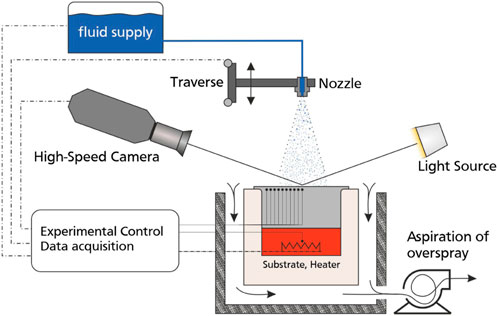
FIGURE 1. Schematic representation of the spray cooling experimental setup.
In Figure 2 all the components involved in the spray generating process are presented. The mixture of water with industrial white lubricant in exact desired ratio, thus achieving desired salt volume concentration, is stored in a reservoir. If an elevated fluid temperature is required, the immersion heater connected to a temperature controller is used. Mostly, in the present experimental campaign, the working fluid remains at ambient temperature, due to the limited need for elevated fluid temperatures in the field of die forging. A one component atomizer is driven by a gear pump, while corresponding fluid properties are measured by a pressure sensor and a temperature sensor. A check valve separates the atomizer from the main supply line. A directional valve connects the supply line to the recirculating line. Finally, a movable shutter is situated immediately beneath the atomizer opening. This shutter can deflect the entire spray that comes out of the atomizer for some amount of time, and serves to eliminate any initial unsteadiness of the flow rate. It moves through the action of a pneumatic cylinder, which instantly pushes the shutter into or out of the fluid stream. When the spray has reached a steady state, the shutter moves out of the flow and the spray can reach the hot substrate. This process prevents large fluid ligaments during the atomizer unstable start-up phase to reach the heated substrate. This configuration ensures development of a stable, full cone spray on the substrate surface.
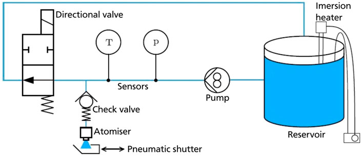
FIGURE 2. Scheme for the atomizer and water supply system used for spray generation [54].
After each spray experiment is completed, a solid residue forms on the substrate, due to the presence of organic salts and surfactants in the lubricant liquid. For high substrate wall temperatures, after water evaporation, deposition of the mentioned components occurs. In order to start the next experiment with the same experimental conditions as the previous one, the substrate surface needs to be thoroughly cleaned. For that purpose, an additional reservoir with a mixture of water and isopropanol is connected with mini-ball valves to a supply line (not presented in Figure 2). Given that organic salts entirely dissolve in water, the aforementioned mixture was chosen for a cleaning liquid. During the cleaning process, the mini-ball valves downstream of the fluid tank are closed in order to supply only the cleaning liquid to the whole system. After thoroughly cleaning the substrate, the visual appearance was checked to identify possible stains or damage to the surface. Upon the end of all experiments and cooling to room temperature, cleaning of the surface was once more done using distilled water. The impact surface was next polished with a mirror polishing paste to attain an average roughness of 0.03 μm. Isopropanol alcohol was subsequently employed to remove polish residuals. Cleaning the surface ensured good repeatability, which is confirmed by repeating of the experiments with the same parameters.
The spray is produced by a liquid driven commercial nozzle (Lechler 490.403), a full-cone, pressure swirl and one component nozzle type. Different impact velocities of the spray droplets are achieved by varying the height of the spray above the hot substrate using a linear traverse. By adjusting the distance between the atomizer and the heated surface, and by varying the pressure supplied to the nozzle, sprays of different impact properties can be generated.
The atomizer has a bore diameter 1.25 mm, spray angle 45° and operating pressure from 1.5 to 10 bar. The upper limit of operational pressure is, however, dictated by the maximum differential pressure of the gear pump. The spray is characterized using phase Doppler measurements and the mass flow rates. The results of these measurements can be found in [54].
In order to measure a flow rate of the fluid passing through the atomizer, a Coriolis mass flow meter (Optimass 7,400 C from Krohne) was installed.
The heating system consists of the spray impact target as a part of a watertight housing, including the heater. The heated target is the top end of a circular cylinder (diameter dt = 100 mm and height ht = 53.2 mm). The target is heated by four cartridge heaters hotset hotrod HHP with an overall power of 2 kW. All the heaters are placed in a copper disc, which is screwed to the bottom of the cylinder. The side and bottom of the target are insulated in order to ensure that heat transfer only occurs through the top surface. The target is placed in a water-resistant housing.
The material of the target is stainless steel with a mirror polished upper surface made by lapping and polishing. The average roughness of the polished surface is
The observation system consists of a CMOS high-speed camera equipped with two different lenses and a backlight illumination source. A camera is Vision Research Phantom v2012 which can achieve a maximum resolution of 1,280 × 800 pixels at 22,000 fps, is used to record side-view images and videos of the spray impact. The high-speed camera is additionally equipped with a Tamron 180 mm macro optical lens. The backlight illumination consists of a high-powered light source (LED Illumination) and a diffuser plate. Illumination is placed behind the spray (and directed co-linear with the high-speed camera) resulting in shadowgraphy imaging.
2.1 Measurement technique for heat flux and surface temperature
In order to evaluate both temperature and heat flux on the surface of the target, the inverse heat conduction problem (IHCP) [55] needs to be solved by using the temperature readings from inside the substrate as input data. The temperature readings are acquired from thermocouples embedded inside the target. In Figure 3 the position of the thermocouples is shown. The thermocouples are arranged in two rows. The first row is located 0.5 mm below the surface to achieve a quick response time. The holes, inside which the thermocouples are placed, are produced using the spark erosion technique. The resulting hole diameter is 0.6 mm. The thermocouples are bonded inside the holes using a thermally high conductive adhesive (Aremco Ceramabond 569 VFG) to ensure good thermal contact. Temperatures are sampled at a sample rate of 95 Hz using National Instruments NI 9212 thermocouple input modules attached to a National Instruments cRio 9074.
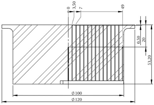
FIGURE 3. Sectional view of the heated target showing the thermocouple positions. Dimensions are in mm.
The radial distance between each sensor in the first row is 3.5 mm to account for any radial distribution of the heat flux. The second row is 20 mm below the surface to make the IHCP procedure independent of the boundary condition at the bottom of the target. The heat flux problem is assumed to be two-dimensional, axisymmetric and having adiabatic boundary conditions at the curved surface area. It is, therefore, assumed, that the heat transfer occurs only through the top surface exposed to spray.
The thermocouples are type K, class 1, with 0.5 mm shield diameter. The measuring tip is open and aligned with the shield. This configuration ensures the shortest possible response time for this type of thermocouples. The response time of the thermocouples was measured, yielding 0.7 s. Such response time makes it problematic to accurately follow the sharp jumps of the temperature and to measure the precise values of heat flux near sharp peaks, for example, in the region of critical heat flux. The measurements are reliable over the entire measurement period except this region. This has been confirmed by comparison of the measured heat flux and predicted using direct numerical simulations of heat conduction in the wall, using a commercial code.
In the present work, an existing algorithm [55,56] is used for calculating the heat flux and target temperature at the wall surface from temperature readings of the thermocouples. Initially, the two-dimensional heat conduction problem is transformed from polar-cylindrical to the Laplace space. Time evolution of the measured temperature inside the target is approximated as a series of half power polynomials in time, and as Fourier-Bessel series in space. After solving the problem in Laplace space, an inverse Laplace transform leads to the solution.
2.2 Preparation of lubricant solutions
The industrial lubricant LUBRODAL F327,1 produced by company Fuchs LUBRITECH, is used as a base for the preparation of the lubricant solutions. The lubricant LUBRODAL F327 represents a water based, water-miscible, die lubricant with excellent separation effects for hot and warm forging of steel. It is widely used for different forging operations in industry due to the quick formation of a clearly visible and touch-resistant lubrication film after spraying to the hot tool surfaces, thus achieving good wetting and reducing the friction between tools and working parts.
The lubricant is supplied as a concentrate, containing a specific amount of organic salts that provide lubrication when utilized. In order to stabilize the concentrate and aid the spreading and formation of the adherent lubricant films on the die surface, organic and inorganic components (surfactants and binders) are present in the lubricant concentrate as well. The exact component present in the concentrate is: Isothiazolone derivative from 0.002% to less than 0.01%. Concentration is given in percent by weight. Prior to experiments, the lubricant is diluted with distilled water to the desired ratio prior to use in the spraying system, thus further decreasing the concentration of the additional components, leaving dissolved organic salts as a dominant influencing factor. Standard values for the dilution of LUBRODAL F 327 with water are from 1:1 for very difficult forging operations, to 1:40 for simple forging operations. The dilution ratio 1:1 was not applied in the present experimental campaign, due to the spraying difficulties of such a dense solution. In the forging industry today, dilution ratios from 1:2 to 1:20 are most common, depending on specific operating properties. For that reason, dilution ratios from 1:2 to 1:16 were used in the present experimental campaign. After diluting, a further stirring of the working mixture is not necessary, because the main component, organic salt, is completely dissolved in water.
Solutions of different salt volume concentrations are prepared by mixing the lubricant concentrate with distilled water. In this study, the volumetric concentrations of the solutions range from φ = 0.97% to φ = 5.47%. Experiments were conducted with 8 different lubricant-to-water mixture ratios, thus achieving different volumetric concentrations. In most industrial applications, the maximum volumetric concentration of φ = 8.2% is typically the upper limit, which is very rarely reached because of the spraying difficulties.
Since the concentration of the organic salts is small, it is expected that most of the thermal properties are similar to that of water. The boiling temperature of the lubricant solution is measured for a few mixture ratios, resulting in boiling temperature of Tsat = 100°C. The surface tension of the different solutions has been measured with a tensiometer. The surface tension of the solutions is respectively: σ = 58.95 mN/m for φ = 5.47%, σ = 61.63 mN/m for φ = 2.34% and σ = 64.28 mN/m for φ = 1.49%.
Since the effects of the additives on the main thermal properties of the solutions in these experiments are minor, one could expect that the outcome of spray cooling will also be similar to that of pure water. In this study we show that addition of salts and surfactants can cause significant changes in the dynamics of spray impact, boiling and therefore in the values of heat flux. These effects are explained in §3.2 and §4.
3 Results and discussions
Experiments in this study were performed with different lubricant-to-water mixture ratios (different organic salt volumetric concentrations), thus achieving various lubricant solution compositions. Additional experiments with the same operational parameters were carried out with a distilled water spray, for comparison purposes.
To evaluate the boiling curve in many heat transfer studies, setup configurations are usually designed to keep the substrate temperature constant. However, in the present case, in order to evaluate effects of transient phenomena during spray cooling and at the same time ensure lubrication of the contact surfaces, the heated target temperature is kept constant only until the spray starts. First, the target is heated until a uniform initial temperature of 445°C is reached. Heating is stopped immediately after the start of spraying, enabling to capture transient phenomena during continuous cooling. Only once the spray has fully developed and the target has been uniformly heated, does the experiment begin.
Throughout the duration of the experiment, the spray parameters are kept constant, with the supply pressure of the atomizer at 2 bar. Visualization and heat flux measurements are temporally matched, and therefore visual observations can be directly associated with the instantaneous local heat flux and target surface temperature.
The spray parameters at the spray axis are the same for all the experiments in this study: the mean drop diameter D10 = 78.7μm, the mean impact velocity U = 14.05 m/s and the mass flux
After each experiment (and complete liquid evaporation), a solid residue remains on the substrate, due to the complexity of the used liquids. In order to start the next experiment with a clean surface, a cleaning liquid is pushed through the system. In this manner, good repeatability throughout the experiments is achieved, with almost identical surface conditions.
3.1 Evolution of the heat flux and the wall temperature during spray cooling
In Figure 4, the results of the measurements of the heat flux
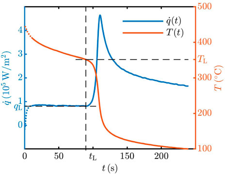
FIGURE 4. Temperature and heat flux at the spray and target axis at the wall surface as a function of time for spray cooling by distilled water. Initial substrate temperature was Tw0 = 445°C.
The effect of the addition of lubricants in the cooling liquid is shown in Figure 5 for various lubricant concentrations. The addition of even a small amount of lubricant, results in significant qualitative and quantitative changes. As the lubricant concentration increases, the local heat flux, the value of critical heat flux and the Leidenfrost point TL increase.
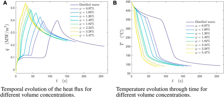
FIGURE 5. (A) Temporal evolution of the heat flux for different volume concentrations. (B) Temperature evolution through time for different volume concentrations. Temperature and heat flux at the spray and target axis at the wall surface as a function of time during spray cooling for different volume concentrations of lubricant solutions. Initial wall temperature was Tw0 = 445°C. The spray parameters are: the mean drop diameter D10 = 78.7 μm, the mean impact velocity U =14.05 m/s and the mass flux
In Figure 6, the dependence of the boiling curves of a lubricant solution φ = 1.49% is shown for different initial wall temperatures. With the increase of wall overheat temperature, different physical mechanisms act on the surface, leading to a substantial increase in heat flux in comparison with the cooling by pure water spray.
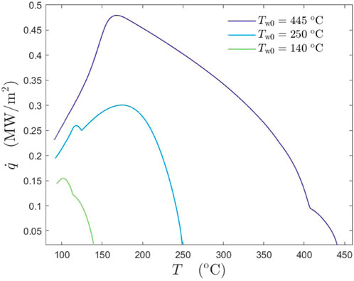
FIGURE 6. Comparison of the boiling curves of a lubricant solution φ = 1.49% for different initial substrate temperatures: Tw0 = 140°C, Tw0 = 250°C and Tw0 = 445°C. The spray parameters are: The mean drop diameter D10 = 78.7 μm, the mean impact velocity U = 14.05 m/s and the mass flux
The significant changes in the values of heat flux shown in Figures 5, 6 cannot be explained only by the variations of the thermal properties of the liquids. It seems that the addition of the lubricants leads to the emergence of the new physical processes, which will be investigated below.
3.2 Phenomena of spray impact onto a hot substrate
To better understand the physical reasons for the strong effect of the additives on the heat flux and on the thermodynamic regimes of spray impact, the phenomena have been observed using a high-speed visualization system. The results of observations of pure water spray and of lubricant solutions are shown in Figure 7. Exemplary snapshots were taken at the surface temperature 280°C. In Figure 7A for impact of a distilled water spray, the observations correspond to the typical fully developed nucleate boiling regime. The same phenomena have been observed also in the recent experiments on spray cooling by distilled water [57]. The observations for the lubricant solutions in Figures 7B, C are completely different. The impact is accompanied by an intensive formation and expansion of a relatively thick foam layer. This phenomenon is probably a main reason of the increase of the heat flux by addition of the lubricants to the sprayed liquid, as shown in Figure 5.
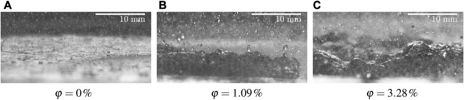
FIGURE 7. Shadowgraphy visualizations of observed phenomena for φ = 0% (distilled water), φ = 1.09% and φ = 3.28%. The spray parameters are: the mean drop diameter D10 = 78.7 μm, the mean impact velocity U = 14.05 m/s and the mass flux
The appearance and the formation of the foam layer at different initial wall temperatures are shown in Figure 8. In all the cases, the first stable bubbles are created by initial drop impacts and their nucleate boiling at the surface. With time the number of bubbles grow, they coalesce and finally create a stable foam. The observations in Figure 8 correspond to the boiling curves shown in Figure 6.
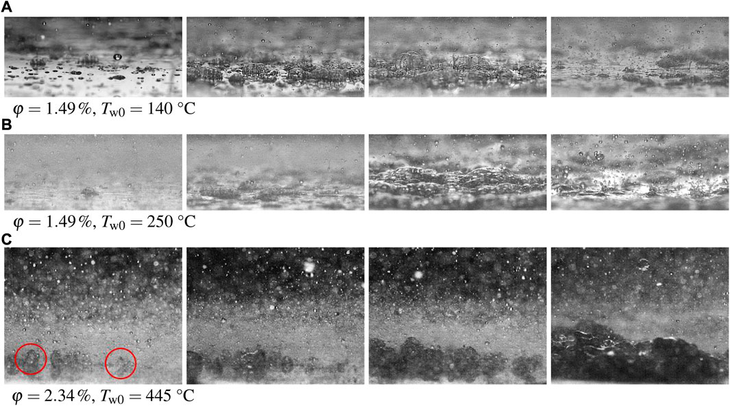
FIGURE 8. Observations of the phenomena accompanied by spray cooling using lubricant solutions φ = 1.49% and φ = 2.34% for different initial wall temperatures. (A) 1.49% solution at 140°C wall temperature, (B) 1.49% solution at 250°C and (C) 2.34% lubricant at 445°C). The development of a foam layer can be clearly seen at all the initial temperatures. The spray parameters are: the mean drop diameter D10 = 78.7 μm, the mean impact velocity U = 14.05 m/s and the mass flux
Now, evolution of the heat flux associated with spray cooling can be explained using a boiling curves for distilled water and for lubricant solution, shown exemplary in Figure 9. The strong difference in the boiling curves of these two liquids is associated with the intensive liquid foaming of the lubricant solutions. As a result of a foam expansion, the cooling process is promoted, resulting in a heat flux increase, (orange line, Figure 9), consequently reaching the critical heat flux point. After reaching CHF and with still continuous spray deposition, breakage of a foaming layer occurs. However, even at low temperatures near saturation temperature, foam is still present as the part of a liquid layer.
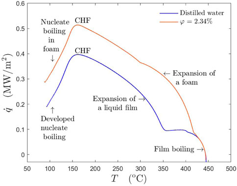
FIGURE 9. Boiling curves for distilled water in comparison with that for a lubricant solution φ = 2.34% for the same initial substrate temperature Tw0 = 445°C. The spray parameters are: the mean drop diameter D10 = 78.7 μm, the mean impact velocity U = 14.05 m/s and the mass flux
4 Suppression of film boiling at high wall temperatures
In the experiments, shown in Figure 5B, the values of the Leidenfrost point increase from approximately 350°C (for distilled water) to 420°C for the lubricant solutions φ = 5.47%. The effect of salt of surfactant additives has also been observed in the literature [22–24,26,30]. It is interesting to understand the mechanism leading to the shift of the Leidenfrost point.
Spreading of a single drop onto a substrate is governed by inertia, viscous stresses and capillary forces. Impact with high Reynolds and Weber number leads to formation of a thin radially spreading lamella. If the thickness of the lamella is much larger than the thickness of the viscous boundary layer, expanding near the substrate, the effect of the viscosity is negligibly small. Remote asymptotic solution for the flow in the lamella, developed from the mass and momentum balance [59,60] yields the expression for the evolution of the lamella thickness in the form
The thickness of the viscous boundary layer in the spreading drop [61] is scaled as
At times t > tν the flow in the lamella is governed by the viscous stresses, which lead to a fast decay of the spreading. The final, residual lamella thickness is scaled well [61] by the expression for hν.
If a single drop impacts onto a hot substrate of the temperature exceeding the saturation temperature of the liquid, a number of vapor bubbles are nucleated at the interface after a certain bubble waiting time [62]. The intensive formation of the bubbles leads to the prevention of the drop receding. The interface temperature of the evaporating bubbles and thus of the wetted substrate surface is close to the saturation temperature [16,57]. The heat transfer in the substrate is governed by the heat conduction in a thin expanding thermal boundary layer of thickness
where ew is the thermal effusivity of the substrate, Tsat is the saturation temperature. The heat from the substrate goes on the liquid evaporation and expansion of the volume concentration of the vapor bubbles.
The residence time of a single drop in the nucleate boiling regime is determined by the balance of the heat transferred from the hot substrate and the heat required for the drop evaporation and splash [16].
where L* is the sum of the latent heat evaporation of the liquid and the enthalpy difference between the initial drop and the saturated liquid. The dimensionless coefficient kw is the geometrical factor based on the spreading area A of a single liquid drop,
The value of the coefficient kw is influenced significantly by the substrate wettability. In the case of lubricate solution, the value of kw increases also due to the drop foaming.
At some instant the volume concentration of the vapor phase reaches the percolation threshold of the liquid phase, associated with the bubble coalescence leading to formation of vapor channels, as shown schematically in Figure 10. This instant is estimated in [17] from the energy balance in the form
where L* is the sum of the latent heat of evaporation L and the enthalpy difference between the initial drop and saturated liquid, ρ is the density of the liquid.
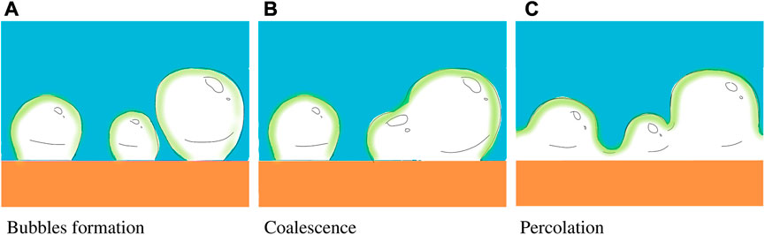
FIGURE 10. Sketch of (A) the nucleation of the vapor bubbles, (B) their random coalescence, leading to the formation and expansion of the vapor channels, and (C) subsequent vapor channels percolation. If the time for channels’ percolation is smaller than the viscous time tν, the consequent drop receding leads to the drop rebound.
If the percolation time tpercolation is smaller than the spreading time, tν the drop boiling is influenced by the vapor channels formation which do not prevent drop receding, unlike what happened during the bubble expansion regime. The condition tpercolation < tν determines therefore the drop rebound temperature [17].
which is linearly proportional to the Leidenfrost temperature tLeidenfrost for spray impact over a wide range of impact parameters and substrate properties. Equation 6 cannot be directly applied to the description of the Leidenfrost point of multi-component liquids since the viscosity of this changes during the drop evaporation, leading to the increase of the concentration of the dispersed or dissolved phase. At the temperature associated with the drop thermal rebound, the relative volume of the liquid phase reduces to the percolation threshold ɛc ≈ 0.32. Therefore, the average concentration of the lubricants at the instant of vapor percolation can be estimated as
To examine the effect of lubricants on the value of the Leidenfrost temperature, let us introduce a dimensionless number
where ΔTrebound,water is based on the Leidenfrost point of distilled water. The measurements of ω are shown in Figure 11 for various concentrations of the lubricant solutions. These results are compared with the experimental data for Leidenfrost point [35,36] for NaCl solutions obtained using the observations of the boiling of a liquid near the surface of a heated immersed metal ball. These results are rather close to the data from this study, which indicates the independence of the phenomena associated with spray impact. Additionally, the data [30] for MgSO4 water solutions are shown in Figure 11, which indicates much stronger effect of MgSO4 on the value of the Leidenfrost temperature.
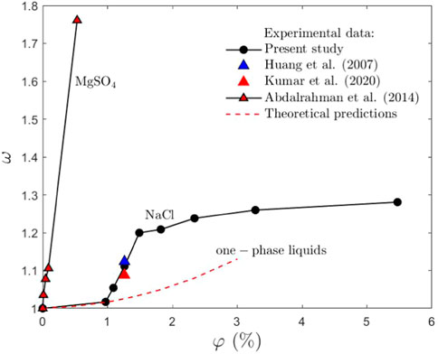
FIGURE 11. Dependence of the dimensionless number ω, defined in Eq. 8) on the lubricant solution concentration φ in comparison with the experimental data for NaCl [35,36], MgSO4 [30] and with the theoretical estimation (Eq. 9), developed for one-phase liquids. The corresponding datasets are in the Electronic Supplementary Material [58].
The results for ω are also compared with the theoretical predictions ωνNaCl, which for the same substrate can be estimated with the help of the expression (Eq. 6)
The viscosity νNaCl of the mixture is determined from the existing database for NaCl solutions [63] for the lubricant concentration φrebound defined in Eq. 7). The theoretical predictions agree well with the measurements only for the smallest concentrations φ < 1%. For larger salt concentrations, the deviation of the measurements and the theory, developed for one-phase liquids, becomes significant. This deviation indicates that we deal with some physical phenomena or processes which become dominant only for the multicomponent liquids and are minor for a pure one-component liquid. These specific phenomena include foaming and substantial changes of the substrate wettability. The processes associated with these phenomena are shown schematically in Figure 12.
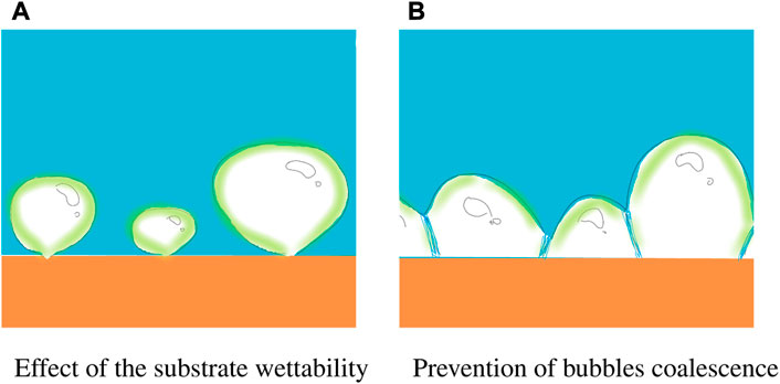
FIGURE 12. Two major mechanisms leading to a significant change of the value of the percolation time and therefore of the Leidenfrost point: (A) increase of the wettability of the substrate after evaporation of the previous lubricant drops in the impacting spray; (B) presence of the surfactants and salts in the lubricant solution prevent the bubbles’ coalescence by formation a stable separating film between bubbles. This phenomenon not only increases the value of the percolation time, but also leads to the formation of a foam.
The first influencing factor is caused by the formation of a hydrophilic spot after impact and evaporation of the first drops in the spray. Formation of these hydrophilic spots has been identified during a series of consecutive impacts of liquid lubricant drops onto a hot substrate. After impact of a first drop, a solid deposited layer remains on the substrate. The impact point of the second, pure water drop was shifted from the center of the deposited layer. It impacts onto an edge of the deposited spot. The outcome of the impact is shown in Figure 13. Almost immediately, the boiling droplet migrates from the edges of the layer towards its center, due to the hydrophilic nature of organic salts [64] forming the deposited layer.
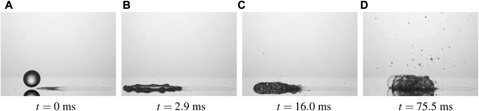
FIGURE 13. Different stages of distilled water drop onto a solid deposited layer from the impact of solution φ = 2.34% at the moment of impact (A), 2.0 ms after impact (B), 16 ms (C) and 76 ms after impact (D). The impact parameters are d0 = 2.2 mm, impact velocity U0 = 1.7 m/s and initial wall temperature 170°C. The corresponding video is in the Electronic Supplementary Material [58].
This leads to the decrease of the projected area of the bubbles on the wall surface, even if the volume of the bubbles remains the same. Correspondingly, the time required to achieve the percolation threshold for the bubbles increases, and thus the Leidenfrost point. The bubbles on the hydrophilic spot are shown schematically in Figure 12A.
The second major mechanism is associated with the presence of the surfactants and salts dissolved in the lubricant. They prevent bubble coalescence, as shown on the sketch in Figure 12B and thus significantly increase the percolation time. The same mechanism leads to the formation of the foam after spray impact onto a hot substrate, as shown in Figure 7.
5 Conclusion
The spray impact of lubricant solutions of different concentrations onto a hot substrate has been investigated in the present work. The heat transfer regimes and the heat flux during the spray cooling process are considerably influenced by the presence of the dissolved organic salts from the lubricant.
The presence of the surfactants and salts in the lubricant solutions leads to a significant increase of heat flux and a significant shift of the Leidenfrost point. The Leidenfrost point is associated with the percolation of the vapor channels formed during drop evaporation at the surface of a very hot substrate. If the time required for percolation is shorter than the typical time of drop impact, the collision with the wall will lead to the rebound.
The aforementioned salts and surfactants significantly increase the percolation time and thus shift the temperature for the drop thermal rebound. Three main mechanisms are identified. The first, which is relevant only for rather small lubricant concentrations, is caused by the viscosity increase of the evaporating liquid. The second mechanism is caused by the increase of the substrate wettability since it is coated by the hydrophobic residuals after previous drop impacts in the spray. And the third reason is associated with the formation of the stable liquid sheets separating the bubbles and preventing their coalescence. The same mechanism also leads to the formation of a foam covering the substrate.
Data availability statement
The original contributions presented in the study are publicly available. This data can be found here: https://zenodo.org/record/7796369#.ZCtB5XvP22E.
Author contributions
CT and IR conceived the project. MG performed the spray cooling experiments with both lubricant solutions and distilled water. JH, IR, and CT were responsible for the scientific coordination of the project. All authors performed the data analysis and its interpretation, and participated in writing the manuscript.
Acknowledgments
The authors gratefully acknowledge financial support from the Deutsche Forschungsgemeinschaft (DFG, German Research Foundation) in the framework of SFB-TRR 75 (TP T02, project number 84292822) and the Open Access Publishing Fund of Technical University of Darmstadt.
Conflict of interest
The authors declare that the research was conducted in the absence of any commercial or financial relationships that could be construed as a potential conflict of interest.
Publisher’s note
All claims expressed in this article are solely those of the authors and do not necessarily represent those of their affiliated organizations, or those of the publisher, the editors and the reviewers. Any product that may be evaluated in this article, or claim that may be made by its manufacturer, is not guaranteed or endorsed by the publisher.
Supplementary material
The Supplementary Material for this article can be found online at: https://zenodo.org/record/7796369#.ZCtB5XvP22E
Footnotes
1https://www.fuchs.com/lubritech/en/product/product/144158-lubrodal-f-327
References
1. Meingast U, Staudt M, Reichelt L, Renz U, Sommerhoff FA. Analysis of spray/wall interaction under diesel engine conditions. SAE Trans (2000) 109:299–312.
2. Lahane S, Subramanian K. Impact of nozzle holes configuration on fuel spray, wall impingement and NOX emission of a diesel engine for biodiesel–diesel blend (b20). Appl Therm Eng (2014) 64:307–14. doi:10.1016/j.applthermaleng.2013.12.048
3. Schmidt A, Bonarens M, Roisman IV, Nishad K, Sadiki A, Dreizler A, et al. Experimental investigation of AdBlue film formation in a generic SCR test bench and numerical analysis using LES. Appl Sci (2021) 11:6907. doi:10.3390/app11156907
4. Chen SJ, Tseng AA. Spray and jet cooling in steel rolling. Int J Heat Fluid Flow (1992) 13:358–69. doi:10.1016/0142-727x(92)90006-u
5. Chen H, Ruan XH, Peng YH, Wang YL, Yu CK. Application status and prospect of spray cooling in electronics and energy conversion industries. Sustainable Energ Tech Assessments (2022) 52:102181. doi:10.1016/j.seta.2022.102181
6. Kim J. Spray cooling heat transfer: The state of the art. Int J Heat Fluid Flow (2007) 28:753–67. doi:10.1016/j.ijheatfluidflow.2006.09.003
7. Panão MR, Moreira AL. Intermittent spray cooling: A new technology for controlling surface temperature. Int J Heat Fluid Flow (2009) 30:117–30. doi:10.1016/j.ijheatfluidflow.2008.10.005
8. Cheng WL, Zhang WW, Chen H, Hu L. Spray cooling and flash evaporation cooling: The current development and application. Renew Sustain Energ Rev (2016) 55:614–28. doi:10.1016/j.rser.2015.11.014
9. Liang G, Mudawar I. Review of spray cooling – part 1: Single-phase and nucleate boiling regimes, and critical heat flux. Int J Heat Mass Transfer (2017) 115:1174–205. doi:10.1016/j.ijheatmasstransfer.2017.06.029
10. Liang G, Mudawar I. Review of spray cooling – part 2: High temperature boiling regimes and quenching applications. Int J Heat Mass Transfer (2017) 115:1206–22. doi:10.1016/j.ijheatmasstransfer.2017.06.022
11. Breitenbach J, Roisman IV, Tropea C. From drop impact physics to spray cooling models: A critical review. Experiments in Fluids (2018) 59:55–21. doi:10.1007/s00348-018-2514-3
12. Yarin AL, Roisman IV, Tropea C. Collision phenomena in liquids and solids. Cambridge, UK: Cambridge University Press (2017).
13. Sodtke C, Stephan P. Spray cooling on micro structured surfaces. Int J Heat Mass Transfer (2007) 50:4089–97. doi:10.1016/j.ijheatmasstransfer.2006.12.037
14. Zhang Z, Li J, Jiang PX. Experimental investigation of spray cooling on flat and enhanced surfaces. Appl Therm Eng (2013) 51:102–11. doi:10.1016/j.applthermaleng.2012.08.057
15. Xu R, Wang G, Jiang P. Spray cooling on enhanced surfaces: A review of the progress and mechanisms. J Electron Packag (2022) 144. doi:10.1115/1.4050046
16. Breitenbach J, Roisman IV, Tropea C. Drop collision with a hot, dry solid substrate: Heat transfer during nucleate boiling. Phys Rev Fluids (2017) 2:074301. doi:10.1103/physrevfluids.2.074301
17. Schmidt JB, Hofmann J, Tenzer FM, Breitenbach J, Tropea C, Roisman IV. Thermosuperrepellency of a hot substrate caused by vapour percolation. Commun Phys (2021) 4:181–8. doi:10.1038/s42005-021-00680-7
18. Breitenbach J, Roisman IV, Tropea C. Heat transfer in the film boiling regime: Single drop impact and spray cooling. Int J Heat Mass Transfer (2017) 110:34–42. doi:10.1016/j.ijheatmasstransfer.2017.03.004
19. Castanet G, Chaze W, Caballina O, Collignon R, Lemoine F. Transient evolution of the heat transfer and the vapor film thickness at the drop impact in the regime of film boiling. Phys Fluids (2018) 30:122109. doi:10.1063/1.5059388
20. Roisman IV, Breitenbach J, Tropea C. Thermal atomisation of a liquid drop after impact onto a hot substrate. J Fluid Mech (2018) 842:87–101. doi:10.1017/jfm.2018.123
21. Singh S, Kukreja R. Experimental study on effects of surfactant and spray inclination on heat transfer performance in nonboiling regime. In: Energy sources, Part A: Recovery, utilization, and environmental effects (2021). p. 1–15. doi:10.1080/15567036.2021.2007313
22. Qiao YM, Chandra S. Spray cooling enhancement by addition of a surfactant. J Heat Transfer (1998) 120:92–8. doi:10.1115/1.2830070
23. Zhang WW, Li YY, Long WJ, Cheng WL. Enhancement mechanism of high alcohol surfactant on spray cooling: Experimental study. Int J Heat Mass Transfer (2018) 126:363–76. doi:10.1016/j.ijheatmasstransfer.2018.05.130
24. Ravikumar SV, Jha JM, Sarkar I, Pal SK, Chakraborty S. Enhancement of heat transfer rate in air-atomized spray cooling of a hot steel plate by using an aqueous solution of non-ionic surfactant and ethanol. Appl Therm Eng (2014) 64:64–75. doi:10.1016/j.applthermaleng.2013.12.008
25. Bandaru R, Jha J, Sarkar I, Mohapatra S, Pal S, Chakraborty S. Achievement of ultrafast cooling rate in a hot steel plate by air-atomized spray with different surfactant additives. Exp Therm Fluid Sci (2013) 50:79–89. doi:10.1016/j.expthermflusci.2013.05.007
26. Liu P, Kandasamy R, Ho JY, Feng H, Wong TN. Comparative study on the enhancement of spray cooling heat transfer using conventional and bio-surfactants. Appl Therm Eng (2021) 194:117047. doi:10.1016/j.applthermaleng.2021.117047
27. Chakraborty S, Sarkar I, Roshan A, Pal S, Chakraborty S. Spray cooling of hot steel plate using aqueous solution of surfactant and polymer. Therm Sci Eng Prog (2019) 10:217–31. doi:10.1016/j.tsep.2019.02.003
28. Cai Z, Wang B, Liu S, Li H, Luo S, Dong Z, et al. Enhancing boiling heat transfer on a superheated surface by surfactant-laden droplets. Langmuir (2022) 38:10375–84. doi:10.1021/acs.langmuir.2c00745
29. S Vara Prasad VVG, Dhar P, Samanta D. Postponement of dynamic Leidenfrost phenomenon during droplet impact of surfactant solutions. Int J Heat Mass Transfer (2022) 189:122675–12. doi:10.1016/j.ijheatmasstransfer.2022.122675
30. Abdalrahman KHM, Sabariman SE. Influence of salt mixture on the heat transfer during spray cooling of hot metals. Int J Heat Mass Transfer (2014) 78:76–83. doi:10.1016/j.ijheatmasstransfer.2014.06.070
31. Cheng W, Xie B, Han F, Chen H. An experimental investigation of heat transfer enhancement by addition of high-alcohol surfactant (HAS) and dissolving salt additive (DSA) in spray cooling. Exp Therm Fluid Sci (2013) 45:198–202. doi:10.1016/j.expthermflusci.2012.11.005
32. Mohapatra SS, Ravikumar SV, Jha JM, Singh AK, Bhattacharya C, Pal SK, et al. Ultra fast cooling of hot steel plate by air atomized spray with salt solution. Heat Mass Transfer (2014) 50:587–601. doi:10.1007/s00231-013-1260-6
33. Pati AR, Behera A, Munshi B, Mohapatra SS. Enhancement of heat removal rate of high mass flux spray cooling by sea water. Exp Therm Fluid Sci (2017) 89:19–40. doi:10.1016/j.expthermflusci.2017.07.012
34. Cui Q, Chandra S, McCahan S. The effect of dissolving salts in water sprays used for quenching a hot surface: Part 2—spray cooling. J Heat Transfer-Transactions ASME - J Heat Transfer (2003) 125:333–8. doi:10.1115/1.1532011
35. Kumar V, Sinha KNR, Raj R. Leidenfrost phenomenon during quenching in aqueous solutions: Effect of evaporation-induced concentration gradients. Soft Matter (2020) 16:6145–54. doi:10.1039/D0SM00622J
36. Huang CK, Carey V. The effects of dissolved salt on the Leidenfrost transition. Int J Heat Mass Transfer (2007) 50:269–82. doi:10.1016/j.ijheatmasstransfer.2006.06.031
37. Ravikumar SV, Jha JM, Tiara A, Pal SK, Chakraborty S. Experimental investigation of air-atomized spray with aqueous polymer additive for high heat flux applications. Int J Heat mass transfer (2014) 72:362–77. doi:10.1016/j.ijheatmasstransfer.2014.01.024
38. Sarkar I, Behera DK, Jha JM, Pal SK, Chakraborty S. Effect of polymer additive on the cooling rate of a hot steel plate by using water jet. Exp Therm Fluid Sci (2016) 70:105–14. doi:10.1016/j.expthermflusci.2015.08.012
39. Pati A, Mandal S, Dash A, Barik K, Munshi B, Mohapatra S. Oil-in-water emulsion spray: A novel methodology for the enhancement of heat transfer rate in film boiling regime. Int Commun Heat Mass Transfer (2018) 98:96–105. doi:10.1016/j.icheatmasstransfer.2018.08.006
40. Gradeck M, Ouattara A, Maillet D, Gardin P, Lebouché M. Heat transfer associated to a hot surface quenched by a jet of oil-in-water emulsion. Exp Therm Fluid Sci (2011) 35:841–7. doi:10.1016/j.expthermflusci.2010.07.002
41. Duursma G, Sefiane K, Kennedy A. Experimental studies of nanofluid droplets in spray cooling. Heat Transfer Eng (2009) 30:1108–20. doi:10.1080/01457630902922467
42. Sanches M, Marseglia G, Ribeiro AP, Moreira AL, Moita AS. Nanofluids characterization for spray cooling applications. Symmetry (2021) 13:788. doi:10.3390/sym13050788
43. Aksoy YT, Zhu Y, Eneren P, Koos E, Vetrano MR. The impact of nanofluids on droplet/spray cooling of a heated surface: A critical review. Energies (2020) 14:80. doi:10.3390/en14010080
44. Arters DC, Macduff MJ. The effect on vehicle performance of injector deposits in a direct injection gasoline engine. SAE Trans (2000) 109:2044–52.
45. Blanken N, Saleem MS, Thoraval MJ, Antonini C. Impact of compound drops: A perspective. Curr Opin Colloid Interf Sci (2021) 51:101389. doi:10.1016/j.cocis.2020.09.002
46. Pack MY, Hu HW, Kim DI, Zheng Z, Stone HA, Sun Y. Failure mechanisms of air entrainment in drop impact on lubricated surfaces. Soft Matter (2017) 13:2402–9. doi:10.1039/c7sm00117g
47. Esmaili E, Chen ZY, Pandey A, Kim S, Lee S, Jung S. Corona splashing triggered by a loose monolayer of particles. Appl Phys Lett (2021) 119:174103. doi:10.1063/5.0059466
48. Thoraval MJ, Schubert J, Karpitschka S, Chanana M, Boyer F, Sandoval-Naval E, et al. Nanoscopic interactions of colloidal particles can suppress millimetre drop splashing. Soft Matter (2021) 17:5116–21. doi:10.1039/d0sm01367f
49. Weickgenannt CM, Zhang Y, Sinha-Ray S, Roisman IV, Gambaryan-Roisman T, Tropea C, et al. Inverse-Leidenfrost phenomenon on nanofiber mats on hot surfaces. Phys Rev E, Stat Nonlinear, Soft Matter Phys (2011) 84:036310. doi:10.1103/physreve.84.036310
50. Piskunov M, Breitenbach J, Schmidt J, Strizhak P, Tropea C, Roisman I. Secondary atomization of water-in-oil emulsion drops impinging on a heated surface in the film boiling regime. Int J Heat Mass Transfer (2021) 165:120672. doi:10.1016/j.ijheatmasstransfer.2020.120672
51. Deegan RD, Bakajin O, Dupont TF, Huber G, Nagel SR, Witten TA. Capillary flow as the cause of ring stains from dried liquid drops. Nature (1997) 389:827–9. doi:10.1038/39827
52. Marin AG, Gelderblom H, Lohse D, Snoeijer JH. Order-to-disorder transition in ring-shaped colloidal stains. Phys Rev Lett (2011) 107:085502. doi:10.1103/physrevlett.107.085502
53. Eral HB, Augustine DM, Duits MH, Mugele F. Suppressing the coffee stain effect: How to control colloidal self-assembly in evaporating drops using electrowetting. Soft Matter (2011) 7:4954–8. doi:10.1039/c1sm05183k
54. Tenzer FM. Heat transfer during transient spray cooling: An experimental and analytical study. Phd thesis. Darmstadt, Germany: Technische Universität Darmstadt (2020).
55. Monde M, Arima H, Liu W, Mitutake Y, Hammad J. An analytical solution for two-dimensional inverse heat conduction problems using Laplace transform. Int J Heat Mass Transfer (2003) 46:2135–48. doi:10.1016/s0017-9310(02)00510-0
56. Woodfield P, Monde M, Mitsutake Y. Improved analytical solution for inverse heat conduction problems on thermally thick and semi-infinite solids. Int J Heat Mass Transfer (2006) 49:2864–76. doi:10.1016/j.ijheatmasstransfer.2006.01.050
57. Tenzer F, Roisman IV, Tropea C. Fast transient spray cooling of a hot thick target. J Fluid Mech (2019) 881:84–103. doi:10.1017/jfm.2019.743
58. Gajevic Joksimovi M, Hussong J, Tropea C, Roisman IV. Spray impact onto a hot solid substrate: Film boiling suppression by lubricant addition. Supplementary Data [Data set] Zenodo (2023). doi:10.5281/zenodo.7796369
59. Yarin AL, Weiss DA. Impact of drops on solid surfaces: Self-similar capillary waves, and splashing as a new type of kinematic discontinuity. J Fluid Mech (1995) 283:141–73. doi:10.1017/s0022112095002266
60. Roisman IV, Berberović E, Tropea C. Inertia dominated drop collisions. I. On the universal flow in the lamella. Phys Fluids (2009) 21:052103. doi:10.1063/1.3129282
61. Roisman IV. Inertia dominated drop collisions. II. An analytical solution of the Navier–Stokes equations for a spreading viscous film. Phys Fluids (2009) 21:052104. doi:10.1063/1.3129283
62. Carey VP. Liquid-vapor phase-change phenomena: An introduction to the thermophysics of vaporization and condensation processes in heat transfer equipment. CRC Press (2020).
63. Kestin J, Khalifa HE, Correia RJ. Tables of the dynamic and kinematic viscosity of aqueous NaCl solutions in the temperature range 20–150 °C and the pressure range 0.1–35 MPa. J Phys Chem Ref Data (1981) 10:71–88. doi:10.1063/1.555641
64. Chen LJ, Hsu MC, Lin ST, Yang SY. Salt effect on wetting/nonwetting behaviors. J Phys Chem (1995) 99:4687–97. doi:10.1021/j100013a046
Nomenclature
t Time [s]
dt Target diameter [mm]
ht Target height [mm]
φ Volume concentration [%]
D10 Mean drop diameter for spray [m]
U Mean droplet velocity for spray [m/s]
d0 Single drop diameter [mm]
U0 Impact velocity of single droplet [m/s]
Re Reynolds number [-]
ρ Density [W/m3]
ν Kinematic viscosity [m2/s]
L Latent heat of evaporation [J/kg]
σ Surface tension [N/m]
αw Thermal diffusivity of the substrate material [m2/s]
ew Thermal effusivity of the substrate material [J/
ω Dimensionless number
h Lamella thickness
T Surface interface temperature [°C]
Tw0 Initial wall temperature [°C]
Tsat Saturation temperature [°C]
TL Leidenfrost temperature [°C]
Trebound Rebound temperature [°C]
Keywords: drop impact, nucleate boiling, film boiling, vapor percolation, white lubricant
Citation: Gajevic Joksimovic M, Hussong J, Tropea C and Roisman IV (2023) Spray impact onto a hot solid substrate: Film boiling suppression by lubricant addition. Front. Phys. 11:1172584. doi: 10.3389/fphy.2023.1172584
Received: 23 February 2023; Accepted: 31 March 2023;
Published: 13 April 2023.
Edited by:
Grazia Lamanna, University of Stuttgart, GermanyReviewed by:
Martin Chabičovský, Brno University of Technology, CzechiaMichel Gradeck, Université de Lorraine, France
Sanjeev Chandra, University of Toronto, Canada
Copyright © 2023 Gajevic Joksimovic, Hussong, Tropea and Roisman. This is an open-access article distributed under the terms of the Creative Commons Attribution License (CC BY). The use, distribution or reproduction in other forums is permitted, provided the original author(s) and the copyright owner(s) are credited and that the original publication in this journal is cited, in accordance with accepted academic practice. No use, distribution or reproduction is permitted which does not comply with these terms.
*Correspondence: Ilia V. Roisman, cm9pc21hbkBzbGEudHUtZGFybXN0YWR0LmRl