 Fernando Sannibale
- Lawrence Berkeley National Laboratory, Berkeley, CA, United States
The successful development in the last two decades of X-ray free electron lasers (FELs) with their revolutionary brightness performance has been tightly dependent on the parallel development of electron guns and injectors capable of providing the high-brightness electron beams required by FELs lasing at these short wavelengths. The ultimate brightness delivered by a linear accelerator (linac) is already set at its injector and the remaining part of the accelerator can be only designed to preserve the injector performance. The technology to be used for the accelerator part of an X-Ray FEL strongly depends on the duty-cycle at which the FEL operates. Normal-conducting, room-temperature, copper-based radio frequency (RF) technology is typically used for low duty-cycles of up to approximately 10−3. For higher duty-cycles and up to continuous wave (CW) operation, the linac must rely on superconductive RF technology because, with the higher duty-cycle, the increasingly higher power dissipated in normal conducting RF structures becomes excessive for the warm technology. The situation changes in the lower energy part of the accelerator, where injector schemes, based on direct current, normal-conducting, and superconducting RF electron guns, are demonstrating the beam quality performance required by high-duty-cycle X-ray FELs. In this paper we start with a description of the requirements for such injectors, followed by an overview of the pursued technologies and schemes, and by a discussion on the main differences in terms of beam dynamics between low and high duty-cycle injectors.
1 Introduction
The X-ray free electron laser (XFEL) revolution that initiated in 2009 with the first lasing at these short wavelengths by the LCLS at the Stanford Linear Accelerator Center (SLAC) [1], provided new opportunities for scientific experiments that were not accessible before. Based on this successful achievement, investments all over the world allowed to create what is now a significant number of such facilities [2]. The LCLS and most of the presently operational XFELs, were designed to operate at relatively low duty cycle (typically less than 10−3—typically with a few microseconds radio frequency (RF) pulses at a few hundred Hz repetition rates). Such a choice was largely driven by the availability of the well-established GHz-class RF technology based on room-temperature copper structures which could be readily used for the linac accelerating sections. Duty-cycles higher than 10−3 were beyond the warm RF technology capability of dissipating the increasing ohmic losses on the accelerating sections walls. Therefore, higher duty-cycle schemes required the use of superconducting RF technology for their linac sections. Indeed, in 2017, the European XFEL at DESY in Germany used superconducting 1.3 GHz niobium accelerating sections in their linac to operate at approximately 10−2 duty cycle [3].
Nevertheless, even before LCLS first lasing, the scientific case for XFELs was already asking for XFELs capable to operate at much high higher duty-cycles, including in continuous wave mode (CW) [4] and several groups around the world started to work for making that possible and projects based on CW linacs, as the LCLS-II at SLAC [5] and SHINE in Shanghai [6], were funded to develop XFELs capable to generate equally spaced laser pulses at MHz-class repetition-rates, and the already operational European XFEL [3] started to consider a higher duty-cycle upgrade [7].
For the sake of this paper scope, before diving into the discussion about the requirements that an XFEL and its injector must satisfy to operate at high-duty-cycles, it is necessary to remind some crucial aspects of the high gain FEL theory. The electron beam brightness B, proportional to the electron beam density in the 6-dimensional phase space, plays a central role in the physics and performance of an FEL:
with Ne is the number of electrons in a bunch, and εnx, εny and εnz are respectively the horizontal, vertical, and longitudinal normalized emittances of the bunch. In general, for optimizing an FEL performance it is necessary to maximize the electron brightness. For the high-gain single-pass FEL applications discussed here, it is in general sufficient to maximize the 4-dimensional transverse component of the brightness by maximizing the number of electrons and minimizing the horizontal and vertical emittances, while using the longitudinal emittance as a knob to control and mitigate the undesired effects of space charge forces inside the bunch.
In the 1-dimensional FEL theory [8], which neglects the effects of the energy spread, diffraction and transverse size of the beam, the overall performance of an FEL is regulated by the parameter ρ defined, in the case of a planar horizontal undulator, as:
where γ in the electron beam energy in rest mass units, Ipeak is the bunch peak current, IA is the Alfven current constant, λu and K are respectively the undulator wavelength and parameter (with K proportional to the undulator peak magnetic field B), JJ is a slow varying function of K (which typically assumes values between 0.6 and 1), βx is the average horizontal beta function and εx is the geometric emittance, with all beam quantities measured inside the undulator. The parameter ρ, which defines among other things, the efficiency and the gain length of an FEL, needs to be maximized for the best FEL performance.
According to the undulator resonant condition λ = λu/2γ2 (1 + K2/2) and considering the technologically available cm-class undulator wavelengths, lasing at the short X-ray wavelengths (λ ∼0.1 to ∼1 nm) requires GeV-class electron beam energies. Unfortunately, Eq. 2 shows that when accounting for the technological limits of undulators in terms of minimum period and maximum B field, higher beam energies lead to smaller ρ parameters.
FELs generates transverse diffraction limited light pulses, so for an efficient lasing the transverse geometric emittance εw of the electron beam must be smaller than or comparable to the photon diffraction limit:
where λ the FEL photon wavelength.
When targeting a particular λ, the beam energy is fixed by the undulator technology and resonance condition. Equation 3 then indicates the requirement that the electron beam emittance must satisfy, and Eq. 2 indicates that the emittance needs to be minimized to optimize the FEL performance. Now, considering that the forces the beam experiences in a linac are with good approximation Hamiltonian, then, for the Liouville theorem, the normalized emittance generated at the injector cannot be decreased along the linac and can only be at best maintained.
In summary, lasing at X-ray wavelengths requires high-energy, high-brightness electron beams, and the ultimate brightness achievable by a linac is already set at its injector (and, as it will be shown, at its electron gun in particular).
Indeed, the development of FELs widely relied on the invention of the RF photo-gun [9], which for the first time allowed to generate electron beams with the brightness required by FELs. It will be shown later in the paper that the brightness of an electron gun beam increases with the electric field intensity that the electrons experience during emission from the cathode and depends on the cathode characteristics, and on the capability of controlling the 3D distribution of the beam during emission [10, 11]. In RF photo-guns, the beam distribution is controlled by the shape of the laser pulse that drives the photoemission, while the required high fields are generated by the resonant RF structures of the gun. Higher RF frequencies generate higher electric fields and hence higher brightness electron beams, which is the reason why most RF guns, built for driving low-duty-cycle FELs and XFELs, are based on GHz-class room-temperature RF technology. This type of guns can operate at high accelerating electric fields (with peak fields beyond 100 MV/m) but with duty-cycles limited to a maximum of approximately 10−2.
The existing TESLA superconducting RF technology [12], successfully used for operating the linac of the European XFEL, was adapted to CW operation and adopted by the LCLS-II and the SHINE projects. Contrarily to the linac case, existing technologies for the electron gun were not available and in response to that, a significant number of groups around the world started to pursue the development of electron guns capable to operate at very high duty-cycles and up to CW.
2 High-duty-cycle injector requirements
Figure 1 shows the schematics with the main components of two typical injector configurations used in high-duty-cycle XFEL applications. The layout with the RF prebuncher is typically used when the energy of the beam at the gun exit is low and the electrons are not fully relativistic yet.
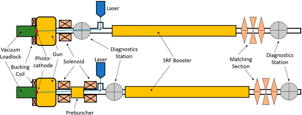
FIGURE 1. Simplified schematics of a high-duty-cycle electron injector in two typical configurations.
Table 1 summarizes the requirements for the main parameters that an electron injector must satisfy to drive a high-duty-cycle XFEL. The ranges of values in the table are based on the results of experimental and/or simulated studies from operational and proposed injectors for high-duty-cycle XFELs (see, for example, [13–20]), and account for the technological limitations that the high duty cycle imposes (more in Section 3). A deeper discussion on the requirements shown in the table, joined, when necessary, by a high-brightness injector physics recap, follows.
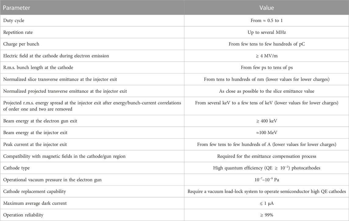
TABLE 1. Ranges for the main parameters of high-brightness, high-duty-cycle electron injectors.
As mentioned in the Introduction, the transverse brightness performance of an electron gun directly depends on the intensity of the electric field that the beam experiences at the cathode during emission (often referred to as the launching field intensity). From an intuitive point of view, higher fields, at the time when the very low energy electrons are emitted from the cathode, allow for a faster acceleration and for an increased rigidity of the newly created electron beam.
The higher rigidity reduces the emittance increase due to intra-bunch space charge forces and Coulomb scattering within the beam particles. Two different operational regimes can be identified, the pancake beam case, where the transverse beam size of the emitted beam is significantly bigger than its longitudinal size, and the cigar beam case, where the opposite is true. In both cases, higher fields at emission (Eemission) lead to higher brightness. For the pancake regime the transverse brightness is [10]:
where k is the Boltzmann constant, and T is the transverse temperature of the electrons in the bunch. While for the cigar regime B is [11]:
where σp is the root mean square (r.m.s.) transverse momentum spread of the particles at extraction, r and Δt are respectively the radius and the pulse length of the laser driving the photoemission.
These expressions indicate two of the most important parameters to focus on when designing high-brightness electron guns: high electric fields at emission and low values for the terms kT and σp, which are just different representations of the r.m.s. momentum component of the intrinsic (sometimes also referred as thermal) emittance of the cathode. Their value depends on the cathode material and on the energy of the photon used for the photoemission.
Equation 5 shows that in the cigar regime, longer laser pulses can be used for increasing the transverse brightness, but at the expense of an increase of the longitudinal emittance. Nevertheless, in most XFEL schemes, this is an acceptable tradeoff because, as mentioned earlier, the lasing performance is mostly defined by the transverse brightness as long as the quality of the longitudinal phase space does not prevent the required bunch compression downstream in the linac. Clearly, there are limits on how long a bunch can be, longer bunches require more compression in the linac, and they also sample more nonlinearities from the time-variable RF fields in the gun and in the linac.
Such nonlinearities introduce correlations in the phase space longitudinal distribution and can also lead to transverse emittance increase [21, 22]. First and second order correlation terms in the longitudinal phase space can be respectively controlled and corrected by properly phasing part of the linac RF and by using higher-harmonic RF linearizers [23] or nonlinear optical systems [24]. Correlations with order higher than 2 cannot be directly controlled and can limit the level of compression in the linac necessary to achieve the few kA peak currents required at the undulator. Simulations indicate that at the injector exit, the residual r.m.s. energy spread associated with the higher order correlations (calculated by removing the linear and quadratic terms) should be contained between several keV and a few tens of keV (with values increasing with charge) [13, 14]. A compensation scheme for the correlations in the longitudinal phase space, based on a buncher with dual RF modes has been recently proposed and planned for the SHINE project [25]. From the transverse plane point of view, a compromise value for the bunch length at the cathode must be struck to balance between minimizing space charge effects, pushing towards longer bunches, and reducing both the compression requirement in the linac and the effects of time-variable RF nonlinearities, which push towards shorter bunches.
Very high electric fields at emission allow to operate the beam in the so-called beam blowout regime where pancake like beams, with very small bunch length to transverse bunch size aspect ratios, are created at the cathode. During the propagation of this beams after the photoemission, space charge forces gradually expand the beam longitudinal and transverse distributions creating an ellipsoidal 3D distribution characterized by dominantly linear internal space charge forces [26]. Linear forces allow for a better emittance compensation (described later in the paper) and also facilitate bunch compression. For a given bunch charge, the blowout regime tends to generate beams with a better longitudinal phase space but with larger transverse emittances when compared with the more conventional regimes previously described. Furthermore, this special regime requires quite high gun fields, and cathode materials with fast photoemission responsivity (metals). Such limitations make the blowout regime a poor match to the requirements of a high-duty-cycle XFEL.
The regimes described by Eqs 4, 5 define the maximum transverse brightness that can be obtained at the cathode and accounts for the cathode contribution to the transverse momentum component of the beam emittance. However, the final normalized emittance εn at end of an injector depends also on other emittance components as shown in the following expression [21]:
where εsc is the space charge component of the emittance, εin is the cathode intrinsic emittance, εRF is the emittance associated with the nonlinear nature of the RF fields used for acceleration, εsol is the result of the quadratic sum of the geometric and chromatic aberrations introduced by the solenoid magnet(s), and εBz Cathode indicates the emittance increase if solenoidal magnetic fields are present on the cathode surface.
The intensity of the space charge forces is directly proportional to the beam charge density. Therefore, in general decreasing the charge density decreases the emittance space charge contribution εsc in Eq. 6. Additionally, the linear component of the space charge force that contributes to εsc can be controlled and eliminated by the technique known as emittance compensation. A qualitative description of the process is provided here and more rigorous descriptions of it can be found in [26, 27]. Longitudinal bunch distributions at the gun exit are generally non-uniform showing current profiles that vary along the bunch. If the beam distribution is conceptually divided into slices, each of such slices will contain a different amount of charge and have a different charge density. Therefore, the intensity of the defocusing space charge force that the particles in the slice experience, which in the linear case is proportional to their radial position, will be different in each of the slices and also different will be the consequent expansion and rotation in the transverse phase space that each slice experiences during the beam propagation. Such differential phase space rotation along the bunch generates an undesired increase of the projected transverse emittance of the bunch. A linear focusing lens, and in particular a solenoid in case of cylindrically symmetric beams, can reverse the slice expansion/rotation and, if its focal length is properly set, also realign the slices phase space at a certain position downstream of the lens minimizing the projected emittance. Such a technique is widely exploited in electron guns where the solenoid(s), visible in Figure 1, is (are) used to perform the just described emittance compensation to get the full slice realignment right at the entrance of the RF booster that, by accelerating the bunch, “freezes” the realigned bunch distribution. Although this technique compensates only for the effects of the linear component of the space charge force, it is still quite important because that component is typically dominant in the core of the bunch.
It was previously mentioned that the cathode intrinsic emittance term εin in Eq. 6 is proportional to the r.m.s. transverse momentum of the beam at the cathode, which depends on the cathode material and on the photon energy used for the photoemission. The term is also proportional to the beam transverse size, which is instead defined by the transverse size of the laser pulse. This last dependence indicates that using the transverse beam size at the cathode as a knob for controlling the bunch charge density is not advisable and must be minimized to avoid increasing the cathode intrinsic emittance contribution. As Eq. 5 suggests, varying the laser pulse length, and consequently the electron bunch length, is a better way to control the charge density in the bunch.
The RF emittance term εRF in Equation 6 is the consequence of the time dependent RF defocusing associated with the accelerating RF fields in the injector. Such a term is proportional to the square of the ratio between the bunch length and the RF wavelength [21, 22] and must be properly accounted because it can potentially limit the use of the bunch length for controlling the bunch charge density. In most XFEL schemes and layouts, but in particular in high-duty-cycle ones, bunch compression starts already in the injector by either using a prebuncher [28] or the so-called velocity bunching technique [29]. Higher compression factors in the injector reduce and simplify the final compression in the downstream main linac. On the other hand, high levels of compression increase the bunch charge density and the associated space charge forces, which applied to the injector beam when it is not fully relativistic, can cause, as was described earlier, emittance degradation and generation of higher order correlations in the longitudinal phase-space distribution. Again, a proper bunch length that balances these contrasting effects must be found.
The term εsol in Eq. 6 indicates that the field of the main solenoid(s) can directly affect the emittance performance of the injector. The magnetic field profile in this critical component must be designed to minimize geometric and chromatic aberrations. Such aberrations strongly depend on the transverse beam size, with fourth and second power dependencies respectively [21, 30]. This also implies that the optics to transport the electron beam to the solenoid must be carefully designed to minimize the beam size inside the magnet. In particular, the distance between the cathode and the first solenoid needs to be minimized to avoid a large transverse expansion of the beam before entering the solenoid.
The last term in Eq. 6 is εBz Cathode. Solenoidal fields at the cathode plane during photoemission add an additional magnetic component to the transverse canonical momentum of the electrons, which is later converted to classical momentum when the electrons propagate to a region where the solenoidal field is zero [31]. This resulting extra momentum component is responsible for the εBz Cathode term in Eq. 6 and consequently, solenoidal fields at the cathode surface must be avoided.
A detailed derivation of the emittance terms in Eq. 6 can be found elsewhere [21, 22, 31].
Minimizing εsc requires, besides a correctly executed emittance compensation, a decrease of the bunch charge density at the gun. This is in part done by increasing the transverse beam size of the beam at the cathode, but by small amounts because as it was said before, larger beam sizes increase the εin term. Most of the charge density control is instead performed by lengthening the bunches, which on the other hand can also increase εRF. Additionally, minimizing the beam size inside the solenoid(s) to control εsol increases the charge density. In summary, all the terms in Eq. 6 that define the final injector emittance depend on the charge density of the bunch (εBz Cathode can be ignored because, as it will be shown in Section 3.4, it can be completely canceled using solenoidal bucking coils). Higher charges per bunch, in general require beams with larger volumes to maintain acceptable charge density, and this, for what has been just described, increases the total beam emittance at the end of the injector. In other words, the final normalized emittance obtainable by an injector depends on the charge of the bunch that is being generated, the larger the charge, the larger the emittance. A quantitative analytical description on how the emittance scales with bunch charge can be found in [32] but it should be remarked that, in designing a real injector, extensive simulation studies are necessary to optimize the final performance in terms of minimal emittance and quality of the longitudinal phase space.
At this point, it is worth reminding the distinction between slice and projected emittances. To that scope, it is useful to conceptually divide the electron bunch into longitudinal slices with length comparable to the FEL cooperation length [8]. The emittance calculated over the particles in a slice is referred to as the slice emittance of that slice. In the 1D FEL theory, the ρ parameter shown in Eq. 2 depends locally on the slice emittances but does not account for potential transverse misalignments between different slices. In the real case, the manipulation that the beam undergoes in the injector and along the linac can generate a significant misalignment among slices. The projected emittance is calculated over the whole bunch. Its value is in general larger than the ones of the slices and assumes a minimum only when no slice misalignment exists. In a well-designed FEL (and injector), the projected and slice emittance values should be as close as possible. A beam with misaligned slices is difficult to transport and does not properly overlap with the photon beam inside the undulator ultimately degrading the FEL performance.
The intensity of the space charge force scales with the inverse square of the beam energy measured in rest mass units, so sufficiently high beam energies at the gun and at the injector exits are necessary for controlling the effects of space charge forces. Experimental and simulation studies indicate that electron gun energies greater than approximately 400 keV are necessary to provide to the beam travelling from the gun to the booster, a sufficient rigidity to undergo the transport, focusing and emittance compensation process with acceptable emittance and longitudinal phase space degradation induced by space charge forces. The energy at the injector exit must be sufficiently high to make space charge effects negligible, but small enough to allow for realistic laser powers and chicane settings at the laser heater [33] [required for controlling the microbunching instability (MBI) [34] during the compression process along the linac]. The energy value of ∼100 MeV in Table 1 represents the compromise typically used in most of the existing operating XFELs.
Independently from the operational duty-cycle of an XFEL, the optimal charge per bunch to be used depends on its specific mode of operation. In most of the schemes, such as self-amplified spontaneous emission (SASE), self-seeding, high gain harmonic generation (HGHG), echo enabled harmonic generation (EEHG), etc. [35, 36], the optimization of the XFEL performance typically converges to a charge per bunch of a few hundreds of pC, which compressed in the injector and along the linac to a few kA bunch peak current required in Eq. 2 to provide the necessary FEL gain [20, 37]. The peak current targeted at the injector exit depends on the bunch charge and on the electric field at the cathode, and from lower to higher charges, ranges from the lower to the higher values shown in Table 1. The final peak current at the end of the injector is controlled by the driving laser pulse length and by the level of compression performed at the injector.
In special XFEL modes of operations, for example, for those optimized for the generation of short photon pulses, lower charges per bunch are preferred. The reason for that starts from the observation that the FEL parameter ρ in Eq. 2 depends on the bunch peak current and not on the total bunch charge. Exploiting this fact, bunches with charges as low as a few tens of pC can be generated at the injector with lower normalized emittance and better longitudinal phase space quality than the ones in bunches with higher charge. These low charge bunches can then be compressed in the linac (with no laser heating and without exciting the MBI in the linac compressors) to kA-class peak currents to generate single-mode, high-power X-ray pulses with less than 10 fs duration [38].
The discussion in this section has pointed out the importance of controlling the bunch distribution at the cathode during electron emission. The most effective way to perform this task in a photo-gun is to properly shape the laser pulse to generate an electron bunch with a distribution that reproduces the one of the laser pulse. More on cathodes and lasers in the next section.
The high electric fields in the injector RF structures, and in particular in the gun, can cause extraction of electrons from the structure walls by field emission. Part of such electrons can then find the right RF phase and be accelerated in the gun and along the injector creating an undesired flux of electrons referred to as dark current. While in low-duty-cycle linacs the average dark current value is in general small and tolerable, in high-duty-cycle or CW injectors significantly large amounts of dark current can be created, which if not controlled, can damage and/or activate accelerator components, quench superconducting structures, generate large radiation doses that could require expensive additional shielding, and limit the maximum accelerating field at cathode. Field emission intensity increases exponentially with the intensity of the electric field [39] and depends on several factors: the material used, the fabrication processes that the material underwent, the surface roughness, the temperature at which the material operates, the contamination by particulates and/or hydrocarbons, and the shape of the components immersed in the high electric field. Dark current can be minimized by controlling/managing those factors but also by a proper design of the electron transport channel and the use of collimators and/or of fast electromagnetic deflectors to selectively remove dark current while minimally affecting the main beam [40].
3 High-duty-cycle injector technologies
The requirement for an injector to operate at high duty-cycles has a profound impact on the technology and schemes that must be used in the different injector subsystems and components. Ultimately, the technological constraints would often impact and define the beam dynamics regime at which the injector operates. XFELs are user facilities and as such, operation reliability at the level of approximately 98% for the whole complex are typically targeted. To be compatible with such a goal, the injectors must perform at reliability levels of ∼99%. This challenging requirement must be also taken into account when selecting the technology to be used for the injector components.
3.1 Photocathodes and lasers
In some materials, photoemission can be already triggered by photons in the near infrared. For example, GaAs-based photocathodes, which belong to this category, are widely used in guns in nuclear physics facilities because of their capability of generating polarized electron beams. In the case of FEL applications, where such a requirement is not necessary, a variety of materials emitting in the visible and in the near ultraviolet (UV), ranging from metals to semiconductors, are used instead. The parameters of a photocathode that are most important for an XFEL application, are the quantum efficiency (QE), indicating the number of electrons emitted per single impinging photon, the QE lifetime, and the work function of the cathode material, which defines the minimum photon energy required for generating photoemission. Another important quantity is σp, the r.m.s. transverse momentum component of the cathode intrinsic emittance, that for most cases depends on the difference between the actual laser photon energy εphoton and the cathode work function (see, for example, Ref. [10]). Most of these quantities are not independent and in general are correlated. In fact, QE increases with εphoton as does σp, so the choice of the photon energy (besides from accounting for the available laser technology) must target values high enough to get reasonably high QEs, but low enough to keep the cathode intrinsic emittance under control.
For high-duty-cycle applications, it is necessary to use cathode materials with high QE in the ∼10−2 range to operate with available and reasonable laser power amounts. Metal cathodes as copper, widely used in low-duty-cycle XFELs, emits in the near UV (∼250 nm) and are in general very robust, chemically stable and with long QE lifetimes, but cannot be used in high-duty-cycle applications because of their low QEs in the ∼10−6–10−4 range. Conversely, QEs in the ∼10−2 range are readily available in semiconductor materials such as, for example, cesium telluride that emits in the near UV or multi-alkali antimonides, which emit in the visible (green). The main disadvantage of semiconductor cathodes is that they are very reactive compounds and hence, to ensure a reasonable QE lifetime, they require very low gun vacuum pressures (as shown in Table 1) with extremely low partial pressures for contaminants such as O2, CO, CO2, hydrocarbons, etc. A thin layer of these semiconductor materials is deposited on a metal plug in separate cathode laboratories and transported to the gun location without exposing them to air in specially designed “vacuum suitcases” [41]. The metal plug is designed to be extracted and inserted into the gun to allow for the periodical replacement of cathodes at the end of their QE lifetime. Exchange of cathodes must be performed without exposing the cathode to air and without breaking vacuum in the gun. Special vacuum load-lock systems are necessary for the operation [41]. Cesium telluride and Multi-alkali antimonide cathodes have already demonstrated their capability of operating at high duty-cycle regimes with the required charge, QE, and QE lifetimes [42–44]. Detailed reviews of cathode materials and of their properties can be found elsewhere [45–47].
It was just discussed that in high-duty-cycle XFELs photocathodes with QEs in the 10−3 to 10−2 range are necessary to generate the required several hundreds of pC electron bunches. In terms of laser specifications that translates to the requirement of several tens of nJ pulse energy at the cathode. The typical scheme used to drive photoemission in photo-guns starts from pulses from near infrared (IR) lasers, which are frequency converted in the visible or in the near UV depending on the photocathode being used. The efficiency of the conversion process depends on how it is performed but in the case of multiple conversions can be as low as 20%. Additional manipulation is also required to control the 3D distribution of the pulses, and this process can also show relatively low efficiencies. Lastly, intensity losses in transporting the photon beam from the laser hall to the electron gun cathode must be considered as well. Accounting for all such inefficiencies conservatively translates into a pulse energy for the IR laser of a few tens of μJ, and, for example, for one MHz repetition rate an IR laser with a total average power of a few tens of W is then necessary. The good news is that lasers with those characteristics are well within the presently available technology and commercial options also exist. As an example, fiber lasers, like the one used by LCLS-II [48], represent a good and convenient option for this type of application.
It was previously discussed that in an electron bunch with an uniform ellipsoidal 3D charge distribution, space charge forces are fully linear and that their effects on beam emittance can be completely mitigated by the emittance compensation process. Generating ellipsoidal electron beams requires either ellipsoidal laser pulses or operating in the previously described beam blowout regime [49] that, for what it was said before, does not represent a good match for XFEL applications. Consequently, a significant R&D effort by various groups around the world is being dedicated to the difficult task of developing pulse shaping techniques capable of generating ellipsoidal laser pulses [50]. In the meantime, significantly simpler techniques are used in FELs to generate “hard-hat” transverse and trapezoidal longitudinal distributions, as compromise distributions that allows to reduce the nonlinear space charge force component in the bunch. A review of laser pulse shaping techniques can be found in [51].
3.2 Photo-guns
Present and proposed low-duty cycle XFELs largely rely on NC high-frequency (GHz-class) copper RF guns to generate their electron beams. These successful types of guns can deliver the electron beam brightness required for an efficient XFEL lasing. Unfortunately, as mentioned before, such schemes cannot be scaled up to the duty cycles values indicated in Table 1 because of the excessive power density that would be dissipated on the gun cavity walls due to ohmic losses [52]. For addressing the need of a high-brightness electron gun capable of driving a high-duty-cycle XFEL, a significant number of groups and resources around the world were dedicated (and are still dedicated) to the development of such an electron source. Schemes based on direct current (DC), super-conducting RF (SRF), and low frequency (100–300 MHz) normal conducting RF (NCRF) technologies were and are pursued, as well as a few hybrid schemes combining some of those technologies.
3.2.1 Normal-conducting room-temperature low-frequency RF guns
A natural extension of the successful high-frequency NC copper gun is represented by schemes where the RF frequency is lowered from the several GHz range down to ∼100–300 MHz, in the so-called very high frequency (VHF) band. The idea behind this scheme consists in exploiting the different scaling with RF frequency (f) existing between the power density dissipated on the RF structure walls and the voltage breakdown threshold in the same structures, which respectively scales as f5/2 and f1/2 [53, 54]. This favorable scaling allows to lower the RF frequency at a point where the power dissipated on the gun walls becomes manageable permitting CW operation while still maintaining the high electric fields at the cathode required for the high brightness performance [55].
Indeed, a NCRF gun, developed for a lower brightness application, was able, using extreme cooling techniques, to run in CW at 700 MHz [56]. On the other hand, by lowering the frequency in the VHF range, the power dissipated in the gun becomes removeable by well-established and reliable conventional water-cooling schemes. Accelerating fields at the cathode during photoemission at approximately and beyond 20 MV/m have been already demonstrated by two NCRF guns operating in CW at ∼200 MHz (VHF-guns in short) [18, 57, 58], and new upgraded configurations targeting fields at and beyond 30 MV/m [59–61] have been proposed. Such fields are approximately a factor two smaller than the ones present at the cathode during photoemission in low-duty-cycle, high frequency NC copper RF guns, and are comparable with those targeted by the SRF guns described in the next sub-section.
At the field levels generated by existing and proposed VHF-guns, the optimal mode of operation for a high-brightness performance is the cigar regime described in Section 1. CW VHF guns can operate at beam repetition rates of hundreds of MHz (limited only by their own RF frequency) but, high-duty-cycle XFEL applications typically require MHz-class repetition rates. NCRF guns are compatible with magnetic fields in the cathode/gun area as necessary for the emittance compensation process. The long period associated with VHF frequencies makes the beam dynamics practically identical to that of a DC gun case, but with much higher gradients and beam energies. The long period also allows for a launching phase at the peak of the RF field, contrarily to the significant de-phasing typically required in GHz-class RF and SRF guns to account for the time it takes to the beam to become sufficiently relativistic inside the gun. High electric fields at the cathode decrease that time and the related de-phasing, but for a fixed electric field, higher RF frequencies increase the de-phasing. The combination of field and RF frequency values in the present GHz-class RF guns produces larger de-phasing with respect to the VHF-gun case.
Additionally, the meter-class long VHF wavelengths permit the inclusion of relatively large apertures in the cavity walls with minimal RF field distortion and so allowing to create a high-conductance vacuum path to externally located pumps, setting the conditions for the very low vacuum pressures required by semiconductor cathodes [62]. Due to resistive losses on the RF structures walls, operating the gun in CW requires RF sources with 100 kW-class power. Such CW power levels are readily achievable/available by solid-state or tetrode-based RF amplifiers.
The first prototype of a VHF-gun, developed at the Berkeley Lab in the framework of the APEX project, demonstrated the high transverse brightness and longitudinal phase space quality required by the LCLS-II high-duty-cycle XFEL [14]. The beam tests were performed only at the charge per bunch of 20 pC due to LCLS-II deadline requirements. The results of these tests validated the simulation predictions providing confidence in the performance predicted also at higher charges. A close version of the APEX gun is now driving the commissioning of the LCLS-II [18] and recently demonstrated XFEL-level brightness with 50 pC charge per bunch [63], A different frequency VHF-gun is also being developed for the SHINE XFELs [64].
3.2.2 Superconducting RF guns
Electron guns based on SRF structures present several important advantages: they are potentially capable of high accelerating fields; the superconducting operation ensures an excellent power efficiency that strongly reduces the RF power requirements; the effective cryo-pumping by the superconducting walls allows for a very good vacuum performance; and the cryogenic temperatures reduce nuclear vibrations that are responsible for the migration of imperfections (dislocations) from the bulk of the cavity walls to their surface where they can potentially become a source of dark current.
On the other hand, they also present challenges. In Section 2, it was shown that the distance between the cathode and the first solenoid is critical for the brightness performance and for the emittance compensation process, and that in general such a distance needs to be minimized. Meissner field exclusion prevents the use of externally applied magnetic fields forcing the use of either cryogenic solenoids or to locate room temperature solenoids downstream of a specially designed compact cold-to-warm transition.
The natural photocathode choice for SRF guns would be to use a superconducting cathode. Niobium, the material typically used for superconducting cavities, shows a low QE of ∼10−5 [65], which makes it not suitable for a high beam repetition rate application. Encouraging initial results from an R&D dedicated to the deposition of a layer of lead (a superconductor below 7.2 K) on niobium have demonstrated QE emissions of ∼10−3 that would allow operation at 100 kHz-class repetition rates [66]. The R&D effort now continues and focuses on improving the process reproducibility, the optimization of the surface roughness, and the characterization of the cathode intrinsic emittance and QE lifetime [47].
A solution in alternative to superconducting cathodes, which allows to satisfy MHz-class beam repetition rates (typically required by high-duty-cycle XFELs), is represented by the same high QE semiconductor cathodes used in the NC guns described in the previous sub-section. In order to use these types of cathodes in SRF guns, several technical issues need to be addressed. First, the warm cathode must be thermally isolated from the superconducting walls to avoid a reduction of the cathode QE and degradation of the SRF performance. Several solutions have been developed and successfully adopted to satisfy this requirement, including the use, in low frequency guns, of relatively simple geometry cathode stalks [17, 67, 68] and, in high frequency guns, the use of RF choke structures for the cathode stalk to minimize the RF loss in the vacuum gap that separates the stalk from the rest of the cavity [67, 69, 70]. Particular attention in designing these cathode support structures is placed in controlling and suppressing multipathing in the area. Second, and similarly to high-duty-cycle NC RF guns, the finite QE lifetimes of such cathodes requires a vacuum load-lock mechanism for swapping cathodes without air exposure. The additional complication in the SRF case is that the swapping operation must happen without generation of particulates that would degrade the SRF performance, potentially limiting the maximum achievable field.
A significant number of groups around the world have been working during the last three decades on the development of SRF photon-guns by pursuing different schemes and approaches. The R&D effort includes guns using SRF structures resonating at high, GHz-class RF frequencies [69, 70] or at low VHF frequencies [17, 68]. Compatibility of operation with semiconductor cathodes K2CsSb [71, 72] and Cs2Te [73] have been already demonstrated and several CW SRF guns are successfully being operated in non XFEL applications.
From the high-duty-cycle XFELs point of view, the simultaneous requirements shown in Table 1, and in particular, the cohabitation between the high-fields at the cathode (≳ 30–40 MV/m) promised by the SRF technology and high-QE semiconductor cathodes, have not been demonstrated yet and more R&D is necessary. From this perspective, the best results achieved so far include: the Wisconsin 200 MHz SRF gun [68], which achieved 20 MV/m at the cathode (corresponding to a beam energy of approximately 1.8 MeV) and that also showed encouraging emittance values with 100 pC charge while operating at a lower field at the cathode [74]; and the SRF 112 MHz gun at the Brookhaven National Laboratory [17], which operating with fields at the cathode of 18 MV/m and at a gun energy of 1.25 MeV, delivered 100 pC beam with a promising emittance but with very long bunches (the peak current at the injector exit was approximately 1–2 orders of magnitude smaller than the values in Table 1).
A recent R&D activity for the development of an SRF gun for an upgrade of the LCLS-II HE project [75] targets a design inspired by the Wisconsin 200 MHz SRF gun. The new gun is designed to generate a beam energy of 1.8 MeV and 30 MV/m fields at the cathode.
A recent review of existing and proposed SRF guns can be found in [75].
3.2.3 Direct current guns
Electron guns based on DC schemes present a number of appealing characteristics. They allow for arbitrarily high repetition rates. They are also compatible with the application of magnetic fields in the cathode/gun area, have demonstrated extremely low vacuum pressures (≲10−9 Pa) and are compatible with pretty much all photocathodes presently under consideration. From the point of view of XFELs, the challenge for DC schemes consists in satisfying the requirements for two of the parameters in Table 1, the electric field at the cathode and the energy at gun exit.
Over the last 20 years, significant R&D activity by many international groups was dedicated to the pursuit of higher beam energies at the gun exit and higher gradients at the cathode. The main limitation to the increase of these parameters is represented by electron field emission induced by the high voltage in the gun metallic parts, which can progressively create charge build up in the gun ceramic insulator that eventually induces a voltage breakdown and ceramic punctuation. Original high-brightness DC guns were designed to achieve beam energies as high as about 750 kV but despite the significant R&D effort, the beam energy at the gun exit was for many years limited to less than 400 keV. Only recently, in 2019, the successful operation at 500 kV was demonstrated by the DC gun developed for JAEA in Japan [76]. This successful step towards higher energies was based on the proper choice of materials and by a careful design of a segmented HV insulator (first proposed by Cornell [77]) composed of many (∼ten) ceramic rings and circular metallic screens assembled in an alternated fashion. The shape of the metallic screens is optimized to shield the ceramic from field emission.
An alternative approach undertaken by some other groups to mitigate field emission and hence to achieve higher DC voltages, is based on the so-called inverted-insulator geometry scheme in which, contrarily to the “classical” approach used in the other DC guns described above, the cathode assembly is supported by the HV ceramic itself. This configuration results in less metal biased at high voltage and consequently to less metal contributing to field emission. As an example, a DC gun with such a geometry developed at JLAB operates at 350 kV with fields at the cathode of about 10 MV/m [78].
With respect to the other schemes being discussed, DC guns are more subjected to cathode damage caused by ion back-bombardment. In general, in all gun schemes, the electron beam ionizes residual gas molecules inside the gun cavity creating positively charged ions. In the case of DC guns, the large majority of these ions are accelerated by the gun field back on the cathode with energies that can be as high as the gun high voltage [79]. In RF guns, due to the fast-varying fields, the number and energy of the ions that make their way back to the cathode are much smaller than those in the DC gun case making ion back bombardment less of an issue [80].
The JAEA gun, and in general most of the other existing or proposed high-voltage DC guns, are designed for driving energy recovery linacs (ERLs), which target operation at very high average currents (tens of mA) at GHz-class repetition rates. In this condition, where a few tens of pC per bunch are necessary, the requirement on the electric field at the cathode can be relaxed. Indeed, the JAEA gun operates at 500 kV at less than 6 MV/m [81], and the Cornell DC gun operates at 400 kV at about 4 MV/m [15, 82].
Despite the low accelerating field at the cathode and low gun energy of it DC gun, the Cornell team was able to demonstrate XFEL-level beam brightness at their injector test facility operating the gun at 395 kV [16]. This was made possible by a combination of several factors, the use of a low thermal emittance semiconductor cathode, and with the DC gun followed by a 1.3 GHz NC prebuncher and by a special capture section composed by a cryomodule with five 2-cell SRF cavities resonating at 1.3 GHz (specially designed for the injector [83]) to accelerate the beam to up 15 MeV [84]. The use of these special short cavities allows to reduce at acceptable levels the RF phase detuning associated with the transit time of the low-energy non-relativistic beam.
3.2.4 Hybrid guns
A hybrid DC-SRF scheme, developed at the Peking University [85], integrates a relatively low voltage (100) kV DC photo-gun in a cryostat containing a 3.5 cell 1.3 GHz SRF cavity. The field on the cathode is limited to about 5 MV/m and the beam energy at the cryostat exit is about 3.5 MeV. The idea behind the scheme is to exploit the advantages of both DC and SRF technologies while eliminating some of the disadvantages. Results of a beam measurement campaign at 2 MeV energy were recently presented at the FEL22 conference reporting normalized emittances of about 0.5, 0.85, and 1.25 μm, respectively achieved at bunch charges of 20 pC, 100 pC, and 260 pC [86].
More recently, a hybrid NC-SRF CW gun scheme, composed of a copper cryocooled NC 0.650 GHz re-entrant cavity followed by a 1.5-cell 1.3 GHz SRF cavity has been proposed [87]. The cathode is inserted in the NC part and the design targets accelerating fields at the cathode higher than the ones in the hybrid DC-SRF scheme described above.
3.3 RF booster and prebuncher
The RF booster accelerates the beam from the gun energy to the one at the exit of the injector. To operate at high-duty-cycle, the booster must use superconducting accelerating cavities to eliminate the RF power losses along the SRF structures and to essentially minimize the required RF power to just the amount necessary to accelerate the beam. The dominant geometry used for the SRF cavities is the 9-cell 1.3 GHz TESLA/TTF [12], but other geometries, as the one used in the Jefferson Lab 1.5 GHz SRF cavities [88], or in the Cornell 2-cell 1.3 GHz specially designed for operating with a low energy gun [83], are used as well. The booster section can be typically composed of one or two cryostats containing the SRF cavities. Two cryostats are mostly used when lower energies guns are present. For example, the Cornell test injector mentioned in the previous section, with its booster cryostat with five of their 2-cells 1.3 GHz cavities, accelerates the beam to approximately 15 MeV. To bring the energy to approximately 100 MeV, as required by an XFEL application, the addition of a second cryomodule with linac-optimized cavities would be necessary. Injectors with higher energy guns can use boosters with either one or two cryomodules. The SHINE injector [89], for example, plans to use a booster composed by a first cryomodule with just one standard 9-cell SRF cavity followed by a second module with eight standard 9-cell cavities. The LCLS-II injector booster uses instead a single standard linac cryomodule with eight standard 9-cell TESLA cavities [90].
Special attention in injectors must be placed to components that can break the cylindrical symmetry of the field inside the cavities. Such asymmetries generate time-dependent transverse kicks to the beam that can increase the beam emittance. An important example of symmetry-breaking component in the booster is represented by the RF couplers that individually feed the RF power to each of the cavities. If a single coupler per cavity is used, the field symmetry is broken and can generate emittance increase. Two options are currently used to mitigate such an effect, building cavities with diametrically opposed identical couplers [91], as in the 2-cell Cornell case, for example, or using a compensation scheme based on skew and normal small quadrupole coils as proposed in [92], demonstrated in [93] and adopted by the LCLS-II injector.
When the beam energy at the gun exit is not fully relativistic, injector layouts can typically include a prebuncher between the gun and the booster (as shown in the layout in the bottom part of Figure 1) to effectively initiate the bunch compression in the injector [28]. This is absolutely necessary in the case of DC gun injectors, see Cornell, for example, [84], but it is also beneficially used in the LCLS-II [90] and SHINE [89] injectors where the energy from their VHF guns is approximately 0.75 MeV. The ballistic compression that prebunchers perform requires an appropriate velocity spread among the bunch particles and for that reason prebunchers are usually not used with beams with energy greater than approximately 1 MeV. Because all injector schemes considered here use photo guns and hence produce electron bunches which are short compared to the period of the linac RF, the prebunchers are not required to operate at sub-harmonic frequencies and can operate at the same RF frequency of the linac. Indeed, prebunchers with different geometries but all operating in CW at 1.3 GHz are used in Cornell [94], APEX [57], LCLS-II [95] and SHINE [89] injector layouts. In all these cases, normal-conducting room-temperature RF cavities are used because of the relatively small RF power requirement.
3.4 Magnets
In the low beam energy part of an injector a major role in terms of beam dynamics is played by solenoidal magnetic fields. To avoid the associated emittance increase described in Section 2, the backing coil visible in Figure 1, is used for cancelling a possible solenoidal field at the cathode surface due to the fringe field of the first solenoid downstream of the gun. The function of the main solenoid(s) is to confine and focus the beam along the beam line and to perform the emittance compensation process previously described [26, 27]. These solenoids are of the electromagnetic type to allow for the required field tunability and, depending on the gun technology adopted in the injector, can be super or normal conducting [96, 97]. As it was discussed before, the design of the longitudinal magnetic field profile is critical because directly impacts the strength of the aberrations in the magnets [21, 30].
At the exit of the injector, the beam energy and rigidity are sufficiently high that the beam cylindrical symmetry can be broken and focusing and matching to the downstream accelerator can be performed by quadrupoles magnets.
Vertical and horizontal steering coils (a.k.a. corrector magnets) must be properly located along the beamline to perform the critical task of aligning the beam through the center of the injector components. Correctors are also used for compensating any orbit steering induced by magnetic and RF fields asymmetries. Steering coils in combination with a beam profile or a position monitor can be used for a first measurement of the beam energy.
Normal and skew quadrupole correcting coils, in general of low intensity, are important in high brightness injectors to compensate for undesired quadrupole components introduced by asymmetries in the RF and in magnetic injector components [92, 93].
A properly designed bend (dipole) magnet at the end of the injector is typically used as part of an energy spectrometer system to allow for accurate beam energy and energy spread measurements.
3.5 Beam diagnostics
The higher heat load associated with high-duty cycle electron beams can represent a challenge for intercepting beam diagnostics in the injector (and in the whole accelerator in general). On the other hand, high repetition rates allow for higher accuracy in non-intercepting beam diagnostics measurements, and for ‘bunch-stealing’ schemes, where one every n-th bunch (where n is a large number) is deflected out in an offline diagnostic beamline by a fast pulsed magnet, allowing for real-time sampling-mode beam measurements.
Beam diagnostic stations in a high-duty-cycle injector are situated in two main locations, in the low beam energy area between the gun and the booster, and in the higher (∼100 MeV) energy part downstream of the booster. In the low energy area, besides the “standard” charge/current, position and profile measurements, the diagnostic suite must also be able of performing emittance measurements, characterizing cathode QE maps, imaging of dark current emitters, and possibly include an extractable Faraday cup to accurately measure dark current.
The high energy diagnostic suite should also allow for most of the measurements performed at the lower energy station, but it should include an energy spectrometer and a transverse deflecting cavity to allow for the characterization of the beam longitudinal phase space and for transverse slice emittance measurements. Examples of beam diagnostics in high-duty-cycle injectors can be found elsewhere [18, 98, 99].
4 Beam dynamics considerations
In this section, the discussion on a few important beam dynamics topics, already touched in the previous sections, is expanded to remark the importance role that they play in high-duty-cycle injectors.
Presently operating CW injectors show a maximum field at the cathode during photoemission smaller or equal to approximately 20 MV/m and proposed upgraded NCRF schemes and SRF guns are now targeting fields in the 30–40 MV/m range. All such fields require the injector to operate from a deep to a moderate cigar regime with relatively long bunches at the cathode and significant compression already in the injector. In this situation, the emittance compensation process needs to be performed simultaneously with the longitudinal compression to progressively reduce the bunch length while accelerating the beam. Due to the complexity of the optimization, and the many parameters to be tuned in the injector, numerical simulations in combination with multi-objective genetic algorithms techniques [100] are typically used for the optimization of the injector performance. These studies, as well as experimental results [14, 16, 19], show that this complex beam manipulation at the injector is possible, and results from start-to-end simulations, where the electron beam is tracked and optimized from the injector exit to the entrance of the XFEL undulator, indicate the capability of these injectors schemes, with relatively low electric field guns, of delivering beams with the quality required by high-duty-cycle XFELs [20, 37].
It was extensively discussed how small transverse normalized emittances are important for the performance of XFELs. It must also be remarked, as evident from Eq. 1, that brightness also depends on the longitudinal emittance, and that a high 6D brightness is in general beneficial to the FEL performance. Indeed, we discussed how highly compressed bunches and hence high peak currents at the FEL undulators directly impact the lasing performance, and how a low uncorrelated energy spread is also preferred because, besides affecting the compression performance, it also affects the X-ray pulse bandwidth and the FEL gain (especially when undulator higher harmonics are considered). Additionally, it was also mentioned that the XFEL special mode of operation, where low charge bunches are used to generate single-mode short-photon pulses, directly benefits from low 6D brightness electron beams.
In the cigar regime, with its relatively long pulses, the longitudinal emittance at the gun is larger than in low-duty-cycle XFELs high field guns that operate closer to the pancake regime. Nevertheless, as it was also mentioned that in XFELs schemes such a disadvantage can often become of secondary importance. In fact, a too small uncorrelated energy spread favors the onset of the microbunching instability (MBI) in the linac magnetic compressors. Consequently, in high charge per bunch operation modes, which with their beam natural energy spread would typically operate beyond the MBI threshold, the uncorrelated energy spread must be purposely increased by a laser heater to control the MBI while preserving an acceptable gain for the FEL process. In such a situation, the uncorrelated energy spread requirements for the injector beam can be significantly relaxed.
5 Conclusion
The requirements for an electron injector to operate in a high-duty-cycle X-ray free electron laser were extensively discussed, with emphasis placed on the technological choices that the high duty-cycle imposes, and on the beam dynamics implications that such choices cause. In particular, it was shown that the generally lower electric fields at the cathode that high-duty-cycle guns typically generate when compared with their low-duty-cycle counterparts, force to relatively longer electron bunches at the gun to control space charge emittance degradation effects. In this regime, emittance compensation and a significant compression at the injector must be simultaneously performed for preserving the emittance and relaxing the compression requirements for the linac. The bunch length at the gun is here used for controlling the charge density minimizing the effects of space charge forces on the beam emittance. It was also pointed out the importance of reducing correlations in the longitudinal phase space, with order greater than two, to avoid limitations to the level of compression achievable in the linac and degradation of the FEL performance.
The most critical component in a photo-injector is in general the electron gun. Unfortunately, the high-frequency, normal-conducting, copper RF photo guns that successfully provide high-brightness beams to the existing low-duty-cycle XFELs, cannot be scaled up to high-duty-cycle operation. This circumstance triggered over the last two-three decades, a formidable R&D effort from various groups around the world to develop a photoinjector capable of the required brightness performance at high duty-cycle. Different schemes based on different technologies, notably direct current (DC), low-frequency normal conducting RF (NCRF), and superconductive RF (SRF), were pursued. All of them are potentially suitable to create a photo-gun able to operate in continuous wave mode and to potentially target the beam brightness required by high-duty-cycle XFELs. Some of these photo-injectors are already delivering beams with the required quality while others are gradually approaching that capability. The LCLS-II at Stanford and the SHINE in Shanghai, the only two high-duty-cycle X-ray FELs presently funded (with the LCLS-II presently under beam commissioning and already delivering high-brightness beams), have adopted injectors with photo-guns based on the NCRF technology. A DC photo-gun has already demonstrated in an especially designed test facility, XFEL quality beams. In general, because of their limited field at the cathode and the low energy of the beams they generate, DC guns require more complex injector layouts with booster sections composed by dual cryomodules housing different types of SRF cavities. A significant number of injectors based on SRF guns are running in CW mode, and several have demonstrated the capability to operate high quantum efficiency warm semiconductor cathodes. A few of these schemes have demonstrated in operation electric fields at the cathode comparable to the ones produced by NCRF guns.
Higher fields at the cathode respect to those presently available, would allow for higher brightness at the gun and, for the same linac energy, would permit to significantly extend the XFEL photon spectrum towards harder X-rays. For this reason, SLAC has initiated an R&D program for the development of an SRF gun targeting fields at the cathode greater than the one available in its present LCLS-II NCRF gun. An R&D at DESY in Hamburg is also pursuing a higher field SRF gun, to be used in a potential high-duty cycle upgrade of the European XFEL. Upgrades of the low frequency NCRF guns targeting electric fields at the cathode comparable to those targeted by the SRF schemes, have been also proposed.
Although a significant number of examples of existing CW injectors and electron guns have been discussed and referenced in this paper, more complete and detailed reviews of operational and R&D injectors can be found elsewhere [64, 82, 101].
Author contributions
The author confirms being the sole contributor of this work and has approved it for publication.
Funding
This work was supported by the Director of the Office of Science of the U. S. Department of Energy under Contract No. DEAC02-05CH11231.
Conflict of interest
The author declares that the research was conducted in the absence of any commercial or financial relationships that could be construed as a potential conflict of interest.
Publisher’s note
All claims expressed in this article are solely those of the authors and do not necessarily represent those of their affiliated organizations, or those of the publisher, the editors and the reviewers. Any product that may be evaluated in this article, or claim that may be made by its manufacturer, is not guaranteed or endorsed by the publisher.
References
1. Emma P, Akre R, Arthur J, Bionta R, Bostedt C, Bozek J, et al. First lasing and operation of an ångstrom-wavelength free-electron laser. Nat Photon (2010) 4:641–7. doi:10.1038/nphoton.2010.176
2. Huang N, Deng H, Liu B, Wang D, Zhao Z. Features and futures of X-ray free-electron lasers. Innovation (Camb) (2021) 2:100097. and references in it. doi:10.1016/j.xinn.2021.100097
3. Decking W, Abeghyan S, Abramian P, Abramsky A, Aguirre A, Albrecht C, et al. A MHz-repetition-rate hard X-ray free-electron laser driven by a superconducting linear accelerator. Nat Photon (2020) 14:391–7. doi:10.1038/s41566-020-0607-z
4. Arenholz E. Toward control of matter: Basic energy science needs for a new class of x-ray light sources. In: Proceedings of the Science for a New Class of Soft X-Ray Light Sources Workshop; October 8–10, 2007; Berkeley, CA (2007). LBNL Report LBNL-1034E, September 24, 2008; Available at http://www.osti.gov/scitech/biblio/941166.
5. Galayda J. The LCLS-II: A high power upgrade to the LCLS. In: Proceedings of IPAC2018; Vancouver, BC, Canada. JACoW (2018). p. 18–23. Geneva.
6. Zhao Z, Wang D, Yang Z, Yin L. Sclf: An 8 GeV CW SCRF linac-based X-ray FEL facility in Shanghai. In: Proceedings of FEL2017; Santa Fe, New Mexico. JACoW (2017). p. 182–4. Geneva.
7. Bazyl D, Chen Y, Dohlus M, Limberg T. CW operation of the European XFEL: SC-gun injector optimization, S2E calculations and SASE performance (2021). arXiv:2111.01756 [physics.acc-ph]. doi:10.48550/arXiv.2111.01756
8. Pellegrini C, Marinelli A, Reiche S. The physics of x-ray free-electron lasers. Rev Mod Phys (2016) 88:015006. doi:10.1103/revmodphys.88.015006
9. Fraser JS, Sheffield RL, Gray ER, Rodenz GW. High-brightness photoemitier injector for electron accelerators. IEEE Trans Nucl Sci (1985) 32:1791–3. doi:10.1109/tns.1985.4333725
10. Bazarov IV, Dunham BM, Sinclair CK. Maximum achievable beam brightness from photoinjectors. Phys Rev Lett (2009) 102:104801. doi:10.1103/physrevlett.102.104801
11. Filippetto D, Musumeci P, Zolotorev M, Stupakov G. Maximum current density and beam brightness achievable by laser-driven electron sources. Phys Rev ST - Accel Beams (2014) 17:024201. doi:10.1103/physrevstab.17.024201
12. Proch D. The TESLA cavity: Design considerations and RF properties. DESY TESLA-REPORT 94-13 (1994).
13. Papadopoulos CF, Corlett J, Emma PJ, Filippetto D, Penn G, Qiang J, et al. Injector optimization for a high repetition rate x-ray FEL. In: Proceedings of FEL2012; Nara, Japan. JACoW (2012). p. 89–92. Geneva.
14. Sannibale F, Filippetto D, Qian H, Mitchell C, Zhou F, Vecchione T, et al. High-brightness beam tests of the very high frequency gun at the Advanced Photo-injector EXperiment test facility at the Lawrence Berkeley National Laboratory. Rev Sci Instrum (2019) 90:033304. doi:10.1063/1.5088521
15. Dunham BM, Sinclair CK, Bazarov IV, Li Y, Liu X, Smolenski KW. Performance of a very high voltage photoemission gun for a high brightness, high average current ERL injector. In: Proceedings of PAC2007; Albuquerque, New Mexico. JACoW (2007). p. 1224–6. Geneva.
16. Gulliford C, Bartnik A, Bazarov I, Dunham B, Cultrera L. Demonstration of cathode emittance dominated high bunch charge beams in a DC gun-based photoinjector. Appl Phys Lett (2015) 106:094101. doi:10.1063/1.4913678
17. Petrushina I, Litvinenko V, Jing Y, Ma J, Pinayev I, Shih K, et al. High-brightness continuous-wave electron beams from superconducting radio-frequency photoemission gun. Phys Rev Lett (2020) 124:244801. doi:10.1103/physrevlett.124.244801
18. Zhou F, Adolphsen C, Benwell A, Brown G, Dowell D, Dunning M, et al. Commissioning of the SLAC linac coherent light source II electron source. Phys Rev Accel Beams (2021) 24:073401. doi:10.1103/physrevaccelbeams.24.073401
19. Papadopoulos CF, Filippetto D, Huang R, Portmann GJ, Qian H, Sannibale F, et al. Longitudinal and transverse optimization for a high repetition rate injector. In: Proceedings of FEL2014 Conference; Basel, Switzerland. JACoW (2014). p. 864–7. Geneva.
20. Marcus G, Ding Y, Emma P, Huang Z, Raubenheimer TO, Wang L, et al. High-fidelity start-to-end numerical particle simulations and performance studies for LCLS-II. In: Proceedings of FEL2015; Daejeon, South Korea. JACoW (2015). p. 342–6. Geneva.
21. Dowell D. Sources of Emittance in RF Photocathode Injectors: Intrinsic emittance, space charge forces due to non-uniformities, RF and solenoid effects. Cornell U physics ArXiv (2016). arXiv:1610.01242v3 [physics.acc-ph].
22. Kim K-J. Rf and space-charge effects in laser-driven rf electron guns. Nucl Instr Methods Phys Res Section A (1989) 275:201–18. doi:10.1016/0168-9002(89)90688-8
23. Zagorodnov I, Dohlus M. Semianalytical modeling of multistage bunch compression with collective effects. Phys Rev ST Accel Beams (2011) 14:014403. doi:10.1103/physrevstab.14.014403
24. Evtushenko P, Benson S, Douglas D. Bunch compression, RF curvature correction and R55, T555 and U5555 measurement at JLab FEL. In: Proceedings of DIPAC2011; Hamburg, Germany. JACoW (2011). p. 15–8. Geneva.
25. Zhu Z, Gu D, Yan J, Wang Z, Yang H, Zhang M, et al. Inhibition of current-spike formation based on longitudinal phase space manipulation for high-repetition-rate X-ray FEL. Nucl Instr Methods Phys Res A (2022) 1026:166172. doi:10.1016/j.nima.2021.166172
26. Serafini L, Rosenzweig JB. Envelope analysis of intense relativistic quasilaminar beams in rf photoinjectors:mA theory of emittance compensation. Phys Rev E (1997) 55:7565–90. doi:10.1103/physreve.55.7565
Carlsten BF. New photoelectric injector design for the los alamos national laboratory XUV FEL accelerator. Nucl Instr Methods Phys Res Section A (1989) 285:313–9. doi:10.1016/0168-9002(89)90472-5
28. Wangler TP. RF linear accelerators, 2nd edition. Wiley-VCH Verlag GmbH & Co KGaA (2008). ISBN: 988-3-528-40680-8.
29. Serafini L, Ferrario M. Velocity bunching in photo-injectors. AIP Conf Proc (2001) 581:88–106. doi:10.1063/1.1401564
30. Bazarov I, Kim A, Lakshmanan MN, Maxson JM. Comparison of dc and superconducting rf photoemission guns for high brightness high average current beam production. Phys Rev ST Accel Beams (2011) 14:072001. doi:10.1103/physrevstab.14.072001
32. Rosenzweig J, Colby E. Charge and wavelength scaling of RF photoinjectors: A design tool. In: Proceedings of the PAC1995; Dallas, TX, USA. JACoW (1995). p. 958–60. Geneva.
33. Emma P, Boyce RF, Brachmann A, Carr R, Decker F-J, Ding Y, et al. First results of the LCLS laser-heater system. In: Proceedings of PAC2009, Vancouver, BC, Canada, JACoW, Geneva (2009), 2358–60. or Z. Huang, et al, Measurements of the linac coherent light source laser heater and its impact on the x-ray free-electron laser performance, Phys. Rev. ST Accel. Beams (2010) 13:020703.
34. Heifets S, Stupakov G, Krinsky S. Coherent synchrotron radiation instability in a bunch compressor. Phys Rev ST Accel Beams (2002) 5:064401. doi:10.1103/physrevstab.5.064401
35. Pellegrini C, X-ray free electron lasers and ultrafast science at the atomic and molecular scale. 2006: Proceedings of the EPAC2006, Edinburgh, Scotland, JACoW, Geneva, 3636–40. and references in there.
36. Stupakov G. Using the beam-echo effect for generation of short-wavelength radiation. Phys Rev Lett (2009) 102:074801. doi:10.1103/physrevlett.102.074801
37. Wang L, Emma P, Nosochkov Y, Raubenheimer T, Woodley M, Zhou F. MOGA optimization design of LCLS-II linac configurations. In: Proceedings of FEL2014; Basel, Switzerland. JACoW (2014). p. 763–8. Geneva.
38. Ding Y, Brachmann A, Decker FJ, Dowell D, Emma P, Frisch J, et al. Measurements and simulations of ultralow emittance and ultrashort electron beams in the linac coherent light source. Phys Rev Lett (2009) 102:254801. doi:10.1103/physrevlett.102.254801
39. Fowler RH, Nordheim L. Electron emission in intense electric fields. Proc R Soc A (1928) 119:173. doi:10.1098/rspa.1928.0091
40. Huang R, Filippetto D, Papadopoulos C, Qian H, Sannibale F, Zolotorev M. Dark current studies on a normal-conducting high-brightness very-high-frequency electron gun operating in continuous wave mode. Phys Rev Spec Top Accel. Beams (2015) 18:013401. doi:10.1103/physrevstab.18.013401
41. Sertore D, Schreiber S, Floettmann K, Stephan F, Zapfe K, Michelato P. First operation of cesium telluride photocathodes in the TTF injector RF gun. Nucl Instr Methods Phys Res Section A (2000) 445:422–6. doi:10.1016/s0168-9002(00)00095-4
42. Sannibale F. High-brightness high-duty cycle electron injectors. Nucl Instr Methods Phys Res Section A (2014) 740:10–6. doi:10.1016/j.nima.2013.10.021
43. Cultrera L, Karkare S, Lillard B, Bartnik A, Bazarov I, Dunham B, et al. Growth and characterization of rugged sodium potassium antimonide photocathodes for high brilliance photoinjector. Appl Phys Lett (2013) 103:103504. doi:10.1063/1.4820132
44. Ding Z, Karkare S, Feng J, Filippetto D, Johnson M, Virostek S, et al. Temperature-dependent quantum efficiency degradation of K-Cs-Sb bialkali antimonide photocathodes grown by a triple-element codeposition method. Phys Rev Accel Beams (2017) 20:113401. doi:10.1103/physrevaccelbeams.20.113401
45. Dowell DH, Bazarov I, Dunham B, Harkay K, Hernandez-Garcia C, Legg R, et al. Cathode R&D for future light sources. Nucl Instr Methods Phys Res Section A (2010) 622:685–97. doi:10.1016/j.nima.2010.03.104
46. Monaco L, Sertore D. Review of recent photocathode advancements. In: To appear in: Proceedings of FEL2022; August 2022; Trieste, Italy (2022).
47. Xiang R, Schaber J. Review of recent progress on advanced photocathodes for superconducting RF guns. Micromachines (2022) 13:1241. doi:10.3390/mi13081241
48. Gilevich S, Alverson S, Carbajo S, Droste S, Edstrom S, Fry A, et al. The LCLS-II photo-injector drive laser system. In: Proceedings of CLEO2020; May 2020; San Jose, CA, USA. IEEE (2020). p. 1–2.
49. Musumeci P, Moody JT, England RJ, Rosenzweig JB, Tran T. Experimental generation and characterization of uniformly filled ellipsoidal electron-beam distributions. Phys Rev Lett (2008) 100:244801. doi:10.1103/physrevlett.100.244801
50. Yu Mironov S, Poteomkin AK, Gacheva EI, Andrianov AV, Zelenogorskii VV, Vasiliev R, et al. Generation of 3D ellipsoidal laser beams by means of a profiled volume chirped Bragg grating. Laser Phys Lett (2016) 13:055003. doi:10.1088/1612-2011/13/5/055003
51. Li Y. Laser pulse shaping, lecture 4 of the course “laser applications to accelerators” at the US particle accelerator, summer 2008 section. University of Maryland (2008). Available at: https://uspas.fnal.gov/materials/08UMD/Lecture4.pdf.
52. Staples JW, Virostek SP, Lidia SM. Engineering design of the LUX photoinjector. In: Proceedings of EPAC2004; Lucerne, Switzerland. JACoW (2004). p. 473. Geneva.
53. Staples J. Frequency scaling VHF photoinjector cavity. CBP Tech Note 395. Lawrence Berkeley National Laboratory (2007). Available at: https://escholarship.org/uc/item/7qr7p7h6.
54. Kilpatrick WD. Criterion for vacuum sparking designed to include both rf and dc. Rev Scientific Instr (1957) 28:824–6. doi:10.1063/1.1715731
55. Staples J, Sannibale F, Virostek S. VHF-Band photoinjector. CBP Technical Note 366, LBNL-1003792 (2006). available at https://inis.iaea.org/search/search.aspx?orig_q=RN:47046088.
56. Nguyen DC, Colestock P, Kurennoy S, Rees D, Regan A, Russell S, et al. Overview of the 100 mA average-current RF photoinjector. Nucl Instr Methods Phys Res Section A (2004) 528:71–7. doi:10.1016/j.nima.2004.04.021
57. Sannibale F, Filippetto D, Papadopoulos CF, Staples J, Wells R, Bailey B, et al. Advanced photoinjector experiment photogun commissioning results. Phys Rev Spec Top Accel. Beams (2012) 15:103501. doi:10.1103/physrevstab.15.103501
58. Sannibale F, Baptiste K, Corlett J, Cork C, De Santis S, Doolittle L, et al. Status of the APEX project at LBNL. In: Proceedings of IPAC2012 Conference; New Orleans, LA, USA. JACoW (2012). p. 2173–5.
59. Sannibale F, Filippetto D, Johnson M, Li D, Luo T, Mitchell C, et al. Upgrade possibilities for continuous wave rf electron guns based on room-temperature very high frequency technology. Phys Rev Accel Beams (2017) 20:113402. doi:10.1103/physrevaccelbeams.20.113402
60. Shu G, Qian H, Lal S, Shaker H, Chen Y, Stephan F. First design studies of a NC CW RF gun for European XFEL. In: Proceedings of 10th Int. Particle Accelerator Conf 19; Melbourne, Australia. JACoW (2019). p. 1698–701. Geneva.
61. Zheng L, Li Z, Du Y, Chen H, Gao B, Li R, et al. Design of a 217 MHz VHF gun at Tsinghua university. In: Proceedings of 10th Int. Particle Accelerator Conf 19; Melbourne, Australia. JACoW (2019). p. 2050–3. Geneva.
62. Wells R, Ghiorso W, Staples J, Huang TM, Sannibale F, Kramasz TD. Mechanical design and fabrication of the VHF-gun, the Berkeley normal-conducting continuous-wave high-brightness electron source. Rev Sci Instrum (2016) 87:023302. doi:10.1063/1.4941836
63. ZhouAdolphsen FC, Dowell D, Xiang R. Overview of CW electron guns and LCLS-II RF gun performance. Front Phys (2023) 11:1150809. doi:10.3389/fphy.2023.1150809
64. Qian H, Vogel E. Overview of CW RF guns for short wavelengths FELs. In: Proceedings of FEL2019; Hamburg, Germany. JACoW (2019). p. 290–6. Geneva.
65. Rao T, Ben-Zvi I, Burrill A, Hahn H, Kayran D, Zhao Y, et al. Design, construction and performance of all niobium superconducting radio frequency electron gun. Nucl Instr Methods Phys Res A (2006) 562:22–33. doi:10.1016/j.nima.2006.02.172
66. Smedley J, Rao T, Warren J, Sekutowicz J, Iversen J, Klinke D, et al. QE measurements of Nb-Pb SRF photo-injector. In: Proceedings of the 41st Advanced ICFA Beam Dynamics Workshop on Energy Recovery Linacs; Daresbury, U. K (2007).
67. Neumann A, Böhlick D, Bürger M, Echevarria P, Frahm A, Glock HW, et al. The bERLinPro SRF photoinjector system-from first RF commissioning to first beam. In: Proceedings of IPAC2018; Vancouver, BC, Canada. Geneva: JACoW (2018). p. 1660–3. Geneva.
68. Legg R, Bisognano JJ, Bissen M, Bosch R, Eisert D, Fisher M, et al. Status of the Wisconsin SRF gun. In: Proceedings of IPAC2012; New Orleans, LA, USA. JACoW (2012). p. 661–3. Geneva.
69. Konomi T, Honda Y, Kako E, Kobayashi Y, Michizono S, Miyajima T, et al. Development of high intensity, high brightness CW SRF gun in KEK. In: Proceedings of SRF2019; July 2019; Dresden, Germany. JACoW (2019). p. 1219–22. Geneva.
70. Teichert J, Arnold A, Ciovati G, Deinert JC, Evtushenko P, Justus M, et al. Successful user operation of a superconducting radio-frequency photoelectron gun with Mg cathodes. Phys Rev Accel Beams (2021) 24:033401. doi:10.1103/physrevaccelbeams.24.033401
71. Wang E, Litvinenko VN, Pinayev I, Gaowei M, Skaritka J, Belomestnykh S, et al. Long lifetime of bialkali photocathodes operating in high gradient superconducting radio frequency gun. Sci Rep (2021) 11:4477. doi:10.1038/s41598-021-83997-1
72. Kühn J, Al-Saokal N, Buerger M, Dirsat M, Frahm A, Jankowiak A, et al. Thermal load studies on the photocathode insert with exchangeable plug for the BERLinPro SRF-photoinjector. In: Proceedings of SRF2019; Dresden, Germany. JACoW (2019). p. 705–8. Geneva.
73. Xiang R, Arnold A, Ma S, Michel P, Murcek P, Schaber J, et al. Study of QE evolution of Cs2Te photocathodes in ELBE SRF GUN-II. In: Proceedings of IPAC2022; Bangkok, Thailand. JACoW (2022). p. 2617–9. Geneva.
74. Bisognano J, Bissen M, Bosch R, Efremov M, Eisert D, Fisher M, et al. Wisconsin SRF electron gun commissioning. In: Proceedings of NAPAC2013; Pasadena, CA, USA. JACoW (2013). p. 622–4. Geneva.
75. Xiang R. Review of superconducting radio frequency gun. In: Proceedings of IPAC2021,; Campinas, SP, Brazil. JACoW (2021). p. 2556–61. Geneva.
76. Nishimori N, Nagai R, Hajima R, Yamamoto M, Honda Y, Miyajima T, et al. Operational experience of a 500 kV photoemission gun. Phys Rev Accel Beams (2019) 22:053402. doi:10.1103/physrevaccelbeams.22.053402
77. Smolenski KW, Dunham BM. Successful laboratory-industrial partnership: The cornell-FRIATEC segmented insulator for high voltage DC photocathode guns. In: Proceedings of NAPAC2016; Chicago, IL, USA. JACoW (2016). p. 405–7. Geneva.
78. Hernandez-Garcia C, Bullard D, Hannon F, Wang Y, Poelker M. High voltage performance of a dc photoemission electron gun with centrifugal barrel-polished electrodes. Rev Scientific Instr (2017) 88:093303. doi:10.1063/1.4994794
79. Grames J, Adderley P, Brittian J, Charles D, Clark J, Hansknecht J, et al. Ion back-bombardment of GaAs photocathodes inside DC guns. In: Proceedings of PAC2005; Knoxville, TN, USA. JACoW (2005). p. 2875–7. Geneva.
80. Qiang J. Particle-in-cell/Monte Carlo simulation of ion back bombardment in a high average current RF photo-gun. Nucl Instr Methods Phys Res A (2010) 614:1–9. doi:10.1016/j.nima.2009.12.001
81. Nishimori N, Nagai R, Matsuba S, Hajima R, Yamamoto M, Miyajima T, et al. Generation of a 500-keV electron beam from a high voltage photoemission gun. Appl Phys Lett (2013) 102:234103. doi:10.1063/1.4811158
82. Nishimori N. Review of experimental results from high brightness DC guns: Highlights in FEL applications. In: Proceedings of FEL2015; Daejeon, Korea. JACoW (2015). p. 269–73. Geneva.
83. Geng RL, Barnes L, Clasby L, Kaminski L, Liepe L, Medjidzade L, et al. Fabrication and performance of superconducting RF cavities for the Cornell ERL injector. In: Proceedings of PAC2007; Albuquerque, NM, USA. JACOE (2007). p. 2340–2. Geneva.
84. Liepe M, Belomestnykh S, Chojnacki E, Medjidzade V, Padamsee H, Quigley P, et al. The Cornell ERL superconducting 2-cell injector cavity string and test cryomodule. In: Proceedings of PAC2007; Albuquerque, NM, USA. JACoW (2007). p. 2572–4. Geneva.
85. Quan S, Hao J, Lin L, Zhu F, Wang F, Feng L, et al. Stable operation of the DC-SRF photoinjector. Nucl Instr Methods Phys Res A (2015) 798:117. doi:10.1016/j.nima.2015.07.025
86. Qin W. Continuous-wave operation of a low-emittance DC-SRF photocathode gun. In: Contributed talk at the 40th International Free Electron Laser Conference (FEL2022); August 2022; Trieste, Italy (2022). No paper submitted to the conference proceedings.
87. Qian H, Krasilnikov M, Stephan F. A cryocooled normal conducting and superconducting hybrid CW photoinjector. In: Proceedings of SRF2019; Dresden, Germany. JACoW (2019). p. 1091–4. Geneva.
88. Reece CE, Daly E, Henry J, Hicks W, Preble J, Wang H, et al. Optimization of the SRF cavity design for the CEBAF 12 GeV upgrade. In: Proceedings of SRF2007; Beijing, China. JACoW (2007). p. 536–9. Geneva.
89. Wang Z, Gu Q, Zhao M, Wang G. Injector physics design at SHINE. In: Proceedings of IPAC2019; Melbourne, Australia. JACoW (2019). p. 1801–3. Geneva.
90. Zhou F, Dowell D, Li R, Raubenheimer T, Schmerge J. LCLS-II injector beamline design and RF coupler correction. In: Proceedings of FEL2015; Daejeon, South Korea. JACoW (2015). p. 77–80. Geneva.
91. Qian H, Kwiatkowski S, Papadopoulos C, Paret Z, Sannibale F, Staples J, et al. Analysis and optimization of coupler kick in APEX. In: Proceedings of PAC2013; Pasadena, CA USA. JACoW (2013). p. 607–9. Geneva.
92. Dowell DH, Zhou F, Schmerge J. Exact cancellation of emittance growth due to coupled transverse dynamics in solenoids and rf couplers. Phys Rev Accel Beams (2018) 21:010101. doi:10.1103/physrevaccelbeams.21.010101
93. Zheng L, Shao J, Du Y, Power JG, Wisniewski EE, Liu W, et al. Experimental demonstration of the correction of coupled-transverse-dynamics aberration in an rf photoinjector. Phys Rev Acc Beams (2019) 22:072805. doi:10.1103/physrevaccelbeams.22.072805
94. Veshcherevich V, Belomestnykh S. Buncher cavity for ERL. In: Proceedings of PAC2003; Portland, OR, USA. JACoW (2003). p. 1–3. Geneva.
95. Qian H, Baptiste K, Doyle J, Filippetto D, Kwiatkowski S, Papadopoulos C, et al. Design of a 1.3 GHz two-cell buncher for APEX. In: Proceedings of IPAC2014; Dresden, Germany. JACoW (2014). p. 3924–6. Geneva.
96. Nielsen G, Hauge N, Krauthammer E, Thaarup K, Baandrup L, Baurichter A. Superconducting solenoids for RF accelerators and electron guns. IEEE Trans Appl Superconductivity (2014) 24:4100205. doi:10.1109/TASC.2013.2280795
97. Vannozzi A, Alesini D, Giribono A, Vaccarezza C. Design and realization of new solenoids for high brightness electron beam injectors. In: Proceedings of IPAC2021; August 2021; Campinas, SP, Brazil. JACoW (2021). p. 2374–7. Geneva.
98. Filippetto D, Byrd J, Chin M, Cork C, De Santis S, Feng J, et al. Low energy beam diagnostic for APEX, the LBNL VHF photo-injector. In: Proceedings of PAC2011; New York, NY, USA. JACoW (2011). p. 1903–5. Geneva.
99. Bazarov I, Belomestnykh S, Chojnacki E, Dobbins J, Dunham B, Ehrlich R, et al. Initial beam results from the Cornell high-current ERL injector prototype. In: Proceedings of PAC2009; May 2009; Vancouver, BC, Canada. JACoW (2009). p. 683–7. Geneva.
100. Bazarov IV, Sinclair CK. Multivariate optimization of a high brightness dc gun photoinjector. Phys Rev Spec Topics-Accelerators Beams (2005) 8:Geneva. doi:10.1103/physrevstab.8.034202
Keywords: FELs, electron injectors, photo-guns, electron sources, X-ray sources, continuous wave
Citation: Sannibale F (2023) High-brightness electron injectors for high-duty cycle X-ray free electron lasers. Front. Phys. 11:1187346. doi: 10.3389/fphy.2023.1187346
Received: 16 March 2023; Accepted: 02 June 2023;
Published: 07 July 2023.
Edited by:
Bo Liu, Chinese Academy of Sciences (CAS), ChinaReviewed by:
Mehdi Abedi-Varaki, Center for Physical Sciences and Technology (CPST), LithuaniaYingchao Du, Tsinghua University, China
Houjun Qian, Zhangjiang Laboratory, China
Copyright © 2023 Sannibale. This is an open-access article distributed under the terms of the Creative Commons Attribution License (CC BY). The use, distribution or reproduction in other forums is permitted, provided the original author(s) and the copyright owner(s) are credited and that the original publication in this journal is cited, in accordance with accepted academic practice. No use, distribution or reproduction is permitted which does not comply with these terms.
*Correspondence: Fernando Sannibale, ZnNhbm5pYmFsZUBsYmwuZ292