- 1School of Naval Architecture, Ocean, and Energy Power Engineering, Wuhan University of Technology, Wuhan, China
- 2School of Naval Architecture and Ocean Engineering, Huazhong University of Science and Technology, Wuhan, China
The acoustic radiation and scattering of underwater bubbles play an important role in ocean exploration, target localization, acoustic measurements, etc. The two-phase fluid flow and moving boundary result in the lack of means to predict the sound field, which limits the exploration of relevant characteristics and mechanisms. The present work is intended to introduce a numerical approach for acoustic radiation and scattering of moving bubbles at low frequencies with CFD-BEM coupling method. The two-phase interface is captured with the volume of fluid scheme and the sound field is solved with the boundary element method. After that, some benchmark problems are solved and the results are compared with data from literatures. Finally, the radiation and scattering of moving bubbles at low frequencies are predicted with our approach. The acoustic radiation pressure of bubbles shows a slight increase trend during deformation. As the ka value increases, both the acoustic directionality of radiation and scattering exhibit main and side lobes, and the scattering energy gradually concentrates in the positive direction of the incident wave. For a moving bubble, its displacement and velocity of moving have a significant impact on the directionality of the scattered sound field. Therefore, the problem of bubble localization can be studied based on directionality shift.
1 Introduction
The research of acoustic radiation in gas-liquid two-phase medium is the theoretical basis for the development of technologies such as ocean exploration, target localization and acoustic measurement. For decades, researchers have conducted extensive and in-depth research on the acoustic radiation and scattering properties of bubbles.
The research of acoustic propagation of bubbles can be traced back to 1917, Rayleigh [1] derived the pressure equation during collapsing bubble based on the phenomenon of sound generated by bubble breakage in boiling water. Then the motion equation of a spherical bubble under incompressible flow conditions was established. Since the Rayleigh’s equation tended to be idealized and cannot accurately describe the behavior of bubbles in reality, many researchers subsequently modified the equation under different conditions [2–5]. Zhang et al. [6] have proposed a bubble dynamic equation that can simultaneously consider the effects of boundary, bubble interaction, environmental flow field, gravity, bubble migration, fluid compressibility, viscosity and surface tension, and achieved good results. Minnaert [7] was the first to study the vibration of bubbles separated from the nozzle He analyzed the small oscillation of a single spherical bubble, and gave an expression for the intrinsic frequency of the bubble. Some researchers paid attention to the violent bubbles with large amplitude vibration, such as bubbles generated by underwater explosion, they analyzed the pulsating pressure and radiation noise produced by collapsing bubble [8–10]. Twersky [11] used the Bessel-Lejeuneade series to characterize the acoustic scattering at a relatively small equivalent frequency (ka) and derived a theoretical solution for the sound scattering of a small sphere. Subsequently, the results of the scattering problem of elastic spheres in fluids were also discussed [12], and these theoretical predictions were confirmed by a large number of experiments [13]. In 1994, Leighton [14] summarized the contents of previous studies on bubble acoustics in different fields and published the book The Acoustic Bubble, and the theoretical system of bubble acoustics was basically established.
Before the 21st century, due to the incomplete understanding of bubbles, the research on the acoustic field of bubbles was mainly focused on the theoretical model. With the rapid development of computers, the improvement of computational efficiency and accuracy has provided great convenience for the numerical simulation of bubble acoustics. Using CFD commercial software to calculate the motion and acoustics of bubbles has been a widely used means [15], such as ANSYS Fluent and COMSOL Multiphysics. The main methods for predicting the acoustic field include the integral equation method [16], the T-matrix method [17], the finite element method (FEM) [18], and the boundary element method (BEM) [19].
The BEM can reduce the computational dimension and improve the computational efficiency, so it was suitable for the calculation of acoustic radiation problems [20]. Chen [21] used the BEM to simulate the underwater acoustic radiation and scattering of multiple stationary objects. Fan [22] studied the acoustic scattering problems of stationary bubbles based on the BEM, and obtained accurate results. Many researchers have also taken different approaches to calculate the acoustic field in the frequency and time domains. Liu [23] combined large eddy simulation and acoustic analogy to predict the acoustic characteristics of bubble formation at the nozzle. Zhang et al. [24] combined radial point interpolation with implicit time integration to analyze the underwater acoustic propagation problem. Cong [25] combined experiments and numerical simulations to analyze the flow pattern and acoustic properties of the bubble. In addition, Chai et al. [26, 27] used FEM and the meshless method to study the distribution of the acoustic field.
With the deeper understanding of bubble acoustics, the research of bubble acoustic radiation and scattering has been gradually improved. However, due to the complexity of flow-acoustic coupling analysis, most of the current studies on acoustic scattering were about stationary objects [28], and there were few studies on the acoustic scattering of moving bubbles. Therefore, this paper calculated the acoustic radiation and scattering of moving bubbles at low frequencies based on the coupled CFD-BEM method. The research is as follows: the calculation method of flow field and the acoustic BEM are introduced in Chapter 2, the calculation procedure of acoustic field used in this paper is verified in Chapter 3, the results with analysis of acoustic radiation and scattering about moving bubbles are shown in Chapter 4 and Chapter 5 respectively, and the conclusions are included in Chapter 6.
2 Numerical model
The motion and acoustic scattering of bubbles in water involve two-phase fluid flow and flow-acoustic coupling process. In this work, the flow field was predicted by the CFD commercial software, which captured the boundary information during the bubble motion based on the volume of fluid method (VOF). Then, the boundary information is used as the initial condition for BEM to calculate the acoustic field. The pressure and velocity at the boundary of a bubble during its movement can be calculated in the flow field, which are transformed into pulsating pressure and vibration velocity that can be used for acoustic calculations through Fourier transform. This CFD-BEM coupling calculation belongs to the one-way coupling and is an explicit algorithm.
2.1 VOF for flow field
The prediction of flow field in present work is based on the Navier-Stokes (N-S) equation, which is based on the following assumptions: 1) the moving of bubble is isothermal and adiabatic, there is no heat transfer occurs with the external environment, 2) the gas and liquid in the model are incompressible Newtonian fluids, 3) the interaction between the gas and liquid happens only at the interface. According to the law of conservation of mass, the continuity equation of fluid motion is deduced as
in which u represents the velocity of the fluid flow, ▽ is the Laplace operator.
According to Newton’s second law, the momentum equation for an incompressible viscous fluid is derived as
in which ρ denotes the density of the liquid, t is the time of moving μ is the viscosity coefficient of the fluid; g is the acceleration of gravity.
Due to the shape of the bubble is changeable, the interface change has a great influence on the movement of bubbles. Various complex phenomena in the movement of bubbles are also related to the interaction of gas-liquid phase at the interface. Therefore, the VOF model is used for the prediction of the bubble surface, tracking the moving interface on the basis of a fixed Eulerian grid. Because the VOF method does not track the movement of fluid particles, it has the advantages of implementation, the amount of calculation and accuracy.
The VOF method is proposed by Hirt [29] in 1981, which is based on the principle that the fluid is divided into target fluid and non-target fluid. Then the fluid is tracked by calculating the volume fraction of each phase in the grid, so as to determine the interface of two phases. The volume function can be obtained as follows.
in which α is the volume of the target fluid in the grid, α represents the volume of gas in this work, Q is the grid volume.
There are three types of results.
(1) C = 0: there is no target fluid in the grid,
(2) 0 < C < 1: the interior of the grid contains both the target fluid and the non-target fluid, which represented as an interface,
(3) C = 1: the interior of the grid is target fluid.
The prediction of the flow field of the bubble in this paper was based on the commercial CFD software ANSYS Fluent. The VOF model and the SIMPLE algorithm was used to solve the N-S equation, the Euler scheme was adopted for the time discretization.t. In addition, the standard k-ε model was adopted as the turbulence model. Under the above conditions, the bubble floating and deformation in the gravity field were simulated. The boundary information of the bubble was captured for the acoustic field calculation.
2.2 BEM for acoustic field
Sound is a mechanical wave existing in elastic medium. Acoustic field is the space where acoustic waves exist. Due to the perturbation of acoustic wave, parameters such as density and pressure of the medium change with time and space. The calculation of the acoustic field in this work is based on the following assumptions: 1) the medium is an ideal fluid without viscosity, 2) the medium is assumed to be homogeneous and stationary, 3) the process of the sound propagating is adiabatic, 4) the amplitude of acoustic wave is small.
Based on the above assumptions, according to the law of conservation of mass (continuity equation), the law of conservation of momentum (equation of motion) and the physical state of the medium (equation of matter), the corresponding linearized equations are obtained by omitting the higher order minima. So as to obtain the linear acoustic fluctuation equation in a homogeneous medium.
in which
Supposing there is a simple harmonic wave in the sound field, the sound pressure at any point can be expressed as
in which P is the amplitude of sound pressure at any point, i is an imaginary unit, and ω is the circular frequency, ω = 2πf, f is the frequency of the wave.
Helmholtz equation can be obtained by bringing Eq. 6 into Eq. 5:
in which k represents the wave number, k = ω/c.
The calculation of the acoustic field is to solve Eq. 7 according to different boundary conditions. The acoustic boundary conditions are generally divided into the following three types: velocity boundary condition (Neumann boundary condition), acoustic pressure boundary condition (Dirichlet boundary condition) and impedance boundary condition (Robin boundary condition). The boundary condition of the bubble is the pressure and velocity are continuous on the bubble surface, Neumann and Dirichlet boundary conditions are both used in the following simulation. It needs to be noted that the velocity and pressure obtained from flow field calculations cannot be directly used as boundary conditions, which require Fourier transform to be coupled into acoustic calculations. Since the radius of the bubble is small relative to the wavelength of the plane wave, the computational situation can be simplified by using the Born approximation [30].
The BEM is based on the integral theorem to transform the differential equation in the solution domain into an integral equation on the boundary. Then the boundary is divided into finite size boundary elements, finally transformed into the algebraic equation to solve. The Helmholtz equation is discretized by Gaussian integration. The types of calculations include internal and external problems. Solving the radiated and scattered sound fields of the bubble belongs to the external problem. The general expression of the boundary integral equation of the field point can be obtained by numerical derivation of Eq. 7 using Green’s formula.
in which v is the vibration velocity, s is the area of integration, n is the normal vector of the integration surface, ψ is the fundamental solution of the accompanying equation.
in which A and B are directional factors, r is the distance from the measuring point to the boundary.
Assuming that the fundamental solution and the sound pressure satisfy Eq. 8, the relationship between the sound pressure at the field point and the boundary information is obtained as follows
Therefore, for the problem of acoustic radiation in the external field, the sound pressure at any field point in the domain can be solved by the sound pressure on the surface of the objects and the vibration velocity of surface particles. However, there is a problem that the solution of boundary integral equation (CBIE) is not unique at the characteristic frequency in the common BEM. The following is the expression of the CBIE for the acoustic scattering problem.
In which, G(x, y) represents the Green’s function, p(x) and q(x) represent the sound pressure and sound flux at the point on the boundary respectively, c(x) determined by the geometric features at point x, pin(x) is the incident sound pressure at point x, Г represents the integral region.
In this work, CHIEF method was used to configure some points (CHIEF points) outside the sound field area. The integral equation of CHIEF points can be combined with the boundary integral equation to form an overdetermined equation, thus solving the problem that the solution is not unique at the characteristic frequency.
In solving the coefficient matrix of boundary nodes, if the computational source point is close to or even coincides with the element node, the fundamental solution of Green’s function has first-order singularity, which affects the calculation accuracy. For the singular integral problem, this paper used the method of coordinate transformation to introduce the Jacobi matrix to eliminate the singular integral.
3 Verification of acoustic BEM program and flow field simulation
Based on the assumptions of sound field calculation given in Chapter 2, the acoustic radiation of the bubble can be calculated by the analytical formula. Then the numerical solution calculated by BEM was compared with the analytical solution to verify the effectiveness of BEM. Subsequently, the accuracy of flow field calculation was verified through grid convergence analysis and literature comparison.
3.1 Acoustic radiation from an infinitely long rigid cylinder
The analytical formula for the acoustic radiation from an infinitely long cylindrical surface in Fourier Acoustics [31] is as follows
where H0 is the Bessel function of the third kind, a is the radius of the cylinder, r is the distance between the measuring point and the cylindrical surface, ρ0 is the medium density, u0 is the vibration velocity of the cylindrical surface, ϕ is the angle in the three-dimensional space. When calculating, a = 1 m, ka = 1, u0 = 1 m/s.
Based on the BEM program, the circumferential boundary of the two-dimensional infinitely and long cylinder was discretized, and was divided into 64 linear elements, as shown in Figure 1A. Due to the symmetry of the cylinder, a Cartesian coordinate system was established with the center of the circle as the coordinate origin. Then, starting from the surface of the cylinder, a total of 40 monitoring points were evenly distributed along the positive direction of the x-axis with a spacing of 1 m. The decreasing trend of acoustic pressure along the positive direction of x-axis was analyzed.
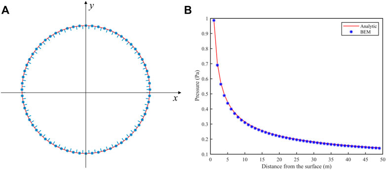
FIGURE 1. (A) Bubble boundary meshing. (B) Comparison between numerical and analytical solutions of acoustic radiation from an infinitely long rigid cylinder.
Figure 1B shows the results of the analytical and numerical solutions of the sound pressure at the field points. At low frequency (ka = 1), the distribution of the sound pressure gradually decreases with the increase of the radiation distance. The sound pressure calculated by the two methods is basically the same, which proves that the analytical solution is in good agreement with the numerical solution. The BEM program used in this work is reliable and can be applied to the next part of the acoustic calculation of the bubble.
3.2 Acoustic scattering from an infinitely long rigid cylinder
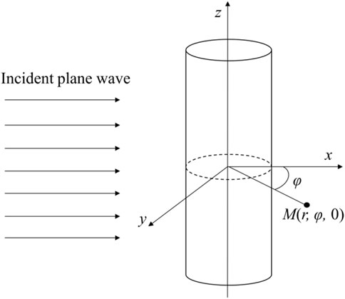
Supposing there is a plane wave propagating along the x-axis, its sound pressure can be expressed as
in which p0 is the amplitude of sound pressure, x is the distance between the field point and the cylindrical surface.
Based on the computational model in Figure 2, the analytical solution of the scattered sound pressure of the far field can be obtained from The Fundamentals of Acoustics [32].
in which r is the monitoring distance, R(φ) is represented as the acoustic directivity function.
in which J is the Bessel function of the first kind, H is the Bessel function of the third kind, φ represents the angle between the monitoring point and the x-axis, εn is a parameter related to n. When calculating, a = 1 m, r = 100 m, p0 = 1 Pa.
The analytical and BEM solutions of the far-field scattering sound pressure calculated at different ka values are given in Figure 3. The distribution of the scattered sound pressure has a clear relationship with ka, both for the theoretical solution and for the BEM. The calculation results of the two methods are in good agreement when ka is small. When ka increases, the finer grid needs to be used to reduce errors. The consistency of the BEM results with the theoretical solutions illustrates the effectiveness of the BEM program used in this work.
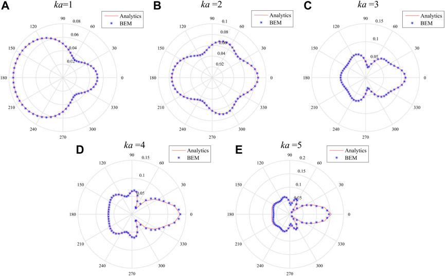
FIGURE 3. Far-field scattering comparison of theoretical and analytical solutions for infinitely long rigid cylinder with different ka values. (A) ka = 1. (B) ka = 2. (C) ka = 3. (D) ka = 4. (E) ka = 5.
3.3 Acoustic scattering from an infinitely long elastic cylinder
The boundary condition of the bubble is different from the rigid cylinder. But the acoustic scattering of the bubble is similar to the scattering result of the infinitely long elastic cylinder [33]. Therefore, the analytical solution of the bubble can be calculated from the scattered sound pressure equation of the infinitely long elastic cylinder.
in which, ε is a parameter that depends on n, ϕ is the angle between the measuring point and the x-axis, An(x) is represented as the acoustic directivity function. When calculating, a = 1 m, r = 100 m, p0 = 1 Pa.
Figure 4 shows the calculation results of analytical solutions and BEM solutions with different ka values. Unlike the rigid cylinder, the energy of the scattered wave of the elastic cylinder is concentrated in the forward direction of the incident wave, which is independent of the increase of the equivalent frequency ka. With the increase of ka (Figures 4B, C), half of the scattered wave energy is concentrated in the positive direction of the incident wave, the other half is evenly distributed in other directions, and the side lobe energy is small. The directional characteristic of the sound pressure of the numerical solution and the theoretical solution at different ka is basically identical, which proves the correctness of the BEM program. On this basis, the acoustic scattering of bubbles under the incidence of plane wave can be discussed.

FIGURE 4. Comparison of the far-field scattering about theoretical and analytical solutions from infinitely long elastic cylinders with different ka values. (A) ka = 1. (B) ka = 3. (C) ka = 5.
3.4 The motion of a bubble in water
In order to verify the correctness of the numerical model used for flow field calculation, it is necessary to conduct simulation of the floating process of a single bubble in a stationary viscous liquid. The geometry model is shown in Figure 5A.
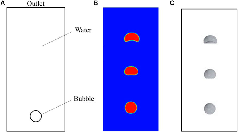
FIGURE 5. (A) Computation model of fluid field. (B) The variation of bubble shape with motion with a grid size of 0.5 mm. (C) The shape changes of the bubble with general cases in the literature.
In Figure 5A, a bubble with a radius of 10 mm is used for calculation, where the width of the calculation domain is 100 mm and the height is 200 mm. The left, right, and lower boundaries of the computational domain are both no-slip wall conditions, with the upper boundary being the pressure outlet and set to atmospheric pressure. Bubble moved upwards from rest under the action of gravity and buoyancy. Three grid systems of different sizes were used for calculation during the simulation process. The grids with lengths of 2, 1, and 0.5 mm were selected for convergence verification. Time steps were all taken as 0.001 s.
Figure 5B shows the morphological change of the bubble during the motion with a grid size of 0.5 mm, which is basically consistent with the calculation results of Zhang and Li [34, 35] (Figure 5C). Through calculation, it was found that there was not much difference in bubble motion among the three grid sizes, and it can be considered that the calculation has reached a convergence state. For the sake of calculation accuracy and efficiency, the size of gird with 1 mm was selected for subsequent calculations.
4 Analysis of acoustic radiation from bubble
Underwater bubble can be seen as a typical monopole sound source, and the pressure pulsation from its own volume change is the main source of its noise generation.
4.1 The capture of bubble boundary
In the calculation of flow field, the movement of bubble within 1s was selected for analysis. The relevant computational parameters taken in the simulation in this section were shown in Table 1.
Figure 6 shows the shape changing of the bubble during the movement. The shape of the bubble after every 0.2 s was shown in Figure 6A. The bubble rising uniformly changes from a sphere to an ellipsoid firstly, then the bottom of bubble gradually depresses inward. With the increase of moving distance, the depression of bubble gradually deepens, and finally appears a cap shape and remains stable floating.

FIGURE 6. Comparison of the bubble boundary. (A) The contour of the bubble. (B) Capturing the bubble boundary.
It can be found from Figure 6B that the boundary of the bubble is captured during the process of motion. The method of boundary capturing selected in this work is based on the air volume fraction. Firstly, deriving the data of all nodes from the fluid computing domain. According to Eq. 4 in Section 2, it can be known that 0 < C < 1 represents the bubble boundary. Therefore, fluid particles within the range of C < 0.5 were selected through programming, and the bubble boundaries were ultimately captured.
4.2 Discussion of acoustic radiation
In the calculation of BEM with frequency, the calculation frequency and vibration frequency about bubble need to be considered. For a spherical bubble in water, the simplified expression for the resonant frequency can be obtained according to the literature [36].
where h is the bubble depth and a is the bubble radius. According to the calculation, the resonant frequency of the bubble was about 300 Hz, so the calculated frequency was chosen as 300 Hz in this paper.
Radiated sound pressure produced by the bubble in uniform linear motion was calculated. Figure 7A is the result of the acoustic radiation generated by the volume vibration caused by the deformation of the moving bubble at the time of 0.2, 0.6, and 1.0 s. The measurement range of the sound field is defined as within 1–100 m in the horizontal direction of the bubble. With the increase of the propagation distance of the sound wave, the pressure of the acoustic radiation decreases gradually. With the increase of movement time, the extreme value of the radiated sound field also increases slightly due to the deformation of the bubble. According to the comparison of bubble shapes at different time in Figure 7. Since the bubble size does not change significantly, the difference in the calculation is not significant.
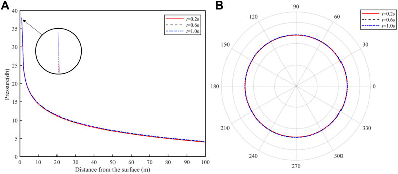
FIGURE 7. (A) Sound pressure of radiation with monitoring distance at different times. (B) The directivity of acoustic radiation.
Figure 7B depicts the acoustic directivity of the bubble at three moments. It can be clearly seen that the directivity of bubble acoustic radiation is uniform, and the sound pressure distribution in all directions is basically the same. The motion of the bubble has no obvious effect on the directivity of the acoustic radiation, but it slightly affects its amplitude. There are two reasons for this phenomenon. One is that the diameter of the bubble is too small, and the impact of deformation can be ignored. The other is that the distance of bubble movement is too short, which can be ignored relative to the length of the monitoring area.
5 Analysis of acoustic scattering from moving bubble
In the sound scattering of the bubble, the bubble can be regarded as a highly compressible elastic sphere. When a free wave encounters the elastic sphere on the propagation path, the sphere is going to have a scattering effect on the sound wave. It can also be considered that the bubble acts as a sound source under the excitation of the incident wave.
The parameters of bubble in the calculation process were the same as Table 1 in Chapter 4. The sound pressure amplitude of incident plane wave was 1 Pa. The calculation domain was taken as a circle with a radius of 100 m to calculate the acoustic scattering in the far field of the bubble.
5.1 A bubble moving in a straight line with uniform velocity
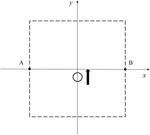
Considering an ideal condition, the bubbles were supposed to be undeformed, and moving uniformly upward at different speeds. The sampling points A and B, 100 m away from the center of the computational domain, were selected as shown in Figure 8. With coordinates of origin (0, 0), the bubble started to rise from (0, −10), and the coordinates of the sampling points were defined as A (−100, 0) and B (100, 0) respectively. The plane wave was assumed to propagate along the positive direction of the x-axis. The sampling point A was defined as being on the back side of the wave propagation direction, and sampling point B was in the forward direction. The bubble has the radius of 1 cm and the velocity of 1 m/s. The amplitude of the sound pressure of the incident wave is 1 Pa.
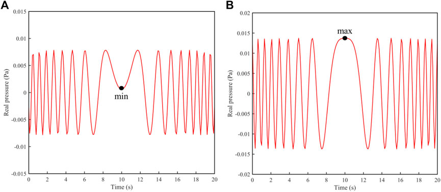
Figure 9 shows the relationship between the scattered sound pressure and time at A and B from 0 to 20 s when ka = 1. The sound pressure at A and B both oscillates with time, and the amplitude of the sound pressure at point B is approximately twice that of point A. This phenomenon also indicates that due to the presence of the bubble, most of the energy of acoustic scattering is concentrated in the front of the sound propagation direction, so the sound pressure at point B is always greater than that at point A. When t = 10 s, the bubble is just at the center of A and B, both A and B have the extreme value of sound pressure. Figure 9A shows the minimum value about A, and Figure 9B shows the maximum value about B. This represents that the forward sound pressure is at its maximum and the reverse sound pressure is at its minimum, reflecting the effect of the bubble on the scattered sound field.
At 100 m away from the bubble, the monitoring points were arranged every 5° and the acoustic directional diagram was drawn. With the motion of the bubble, the sound field changes, which can be demonstrated by the change in the acoustic directivity. This work defined the directional offset angle θ as shown in Figure 10E. θ represents the angle between the maximum sound pressure under two working conditions (the red solid line represents the distribution of acoustic filed at the initial moment of the bubble, and the blue dashed line represents the scattered sound field after a period of bubble movement).
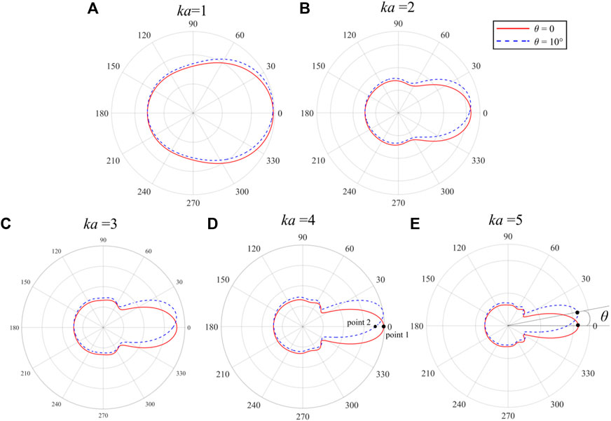
FIGURE 10. The change of the directivity of the acoustic scattering under different ka. (A) ka = 1. (B) ka = 2. (C) ka = 3. (D) ka = 4. (E) ka = 5.
It can be found that ka also has an effect on the distribution of the acoustic scattering in Chapter 3. Therefore, the comparison of θ = 10° under different ka was plotted in Figure 10. Figure 10 depicts the change in directionality offset caused by bubble motion, with the position of measurement points unchanged. The presence of the bubble has almost no obstruction effect on the sound wave, so that the energy of the acoustic scattering is mainly concentrated in the forward direction of the incident wave. When ka is small (Figure 10A), the directivity of the acoustic scattering in the far-field of the bubble is not very obvious, and no side lobes are produced. As ka increases, the distribution of sound pressure gradually has obvious directivity, the main lobe and a small part of the side lobes appear (Figures 10D, E).
According to the deviation of acoustic directivity, it is found that ka does not have much effect on the backward scattering. When ka increases, the shift of the main lobe becomes more obvious. That is, the larger the ka is, the more intense the disturbance of bubble motion on the acoustic field.
In order to further discuss the effect of bubble motion on sound field, the displacement and velocity of bubble motion required for θ = 1°, 5°, 10° at different ka were calculated. In Figure 11, H is the height of the bubble rising in the straight line, V is the speed of bubble motion, C is the speed of sound, and L is the radius of the monitoring domain, C = 1,500 m/s, L = 100 m.
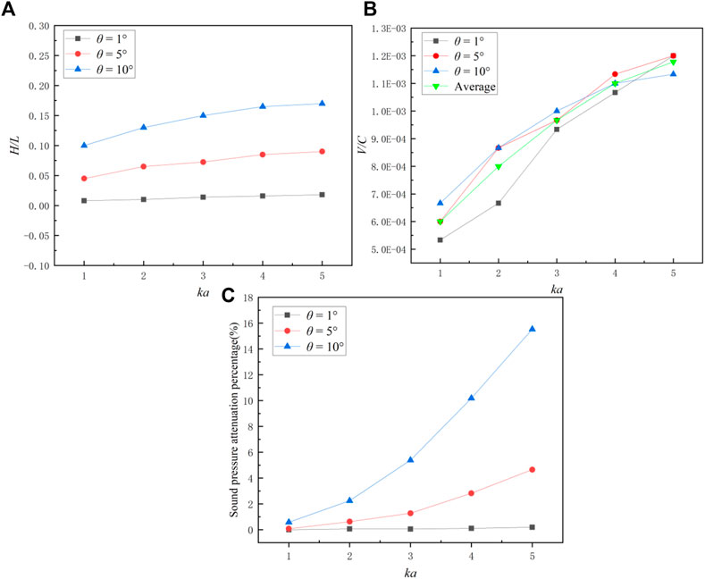
FIGURE 11. Changes of parameters of acoustic scattering when bubble moves at different ka. (A) Movement distance. (B) Movement speed. (C) Percentage of sound pressure attenuation.
Figure 11A depicts the effect of bubble moving displacement on sound scattering, representing the distance traveled by the bubble (v = 1 m/s) when the directionality offset angle θ = 1°, 5°, 10°. Obviously, as the displacement of moving increases, the θ also increases. At the same θ, as the ka increases, the distance of bubble movement also needs to increase. When the offset angle θ = 1, the motion distance of the bubble is 100 times radius of the bubble at least. This proves that the distance the bubble moves has some effect on the sound pressure of far-field, the farther the bubble moves, the more pronounced the change in directivity.
In this paper, the acoustic directivity changing velocity is defined as
in which t is the time the bubble moves. w is used to evaluate the velocity of acoustic directionality shift, representing the angle that a bubble movement of 1 s can cause the point of maximum sound pressure to move, the unit is ° s−1.
Figure 11B shows the bubble velocity v corresponding to θ = 1°, 5°, 10° when w = 1°·s−1, representing the relationship between the offset velocity of acoustic directionality and the velocity of the bubble. As ka increases, the bubble velocity v also needs to increase when θ is fixed. When ka is small, the increase of v is proportional to θ. When ka is large, the speed corresponding to different offset angles θ has no obvious relationship. The average of the velocities at the three offset angles θ can be used to represent the velocity that a bubble needs to reach when w = 1°·s−1. It can be seen that within the same movement time, the increase in bubble velocity does not cause a more significant shift in directionality.
Such as shown in Figure 10D, this work defined the percentage of sound pressure attenuation in the direction of 0° at a certain offset angle θ as
where p1 is the sound pressure at point 1 in Figure 10D and p2 is the sound pressure at point 2.
Figure 11C discusses the percentage of sound pressure attenuation at different θ under different ka, representing the influence of bubble motion on the sound pressure in the positive x-axis direction. When θ = 1°, ka has no significant effect on the sound pressure in the direction of 0°. However, the influence of ka on attenuation of sound pressure increases when the θ increases. In addition, when ka is small, the offset angle of the acoustic directivity θ has little effect on the sound pressure attenuation. When ka is large, the increase of the θ will rapidly reduce the sound pressure value in the direction of 0°. This indicates that within a fixed monitoring domain, the upward movement of the bubble will reduce the sound pressure in the x-axis direction, and the farther the bubble moves, the more significant the decrease in the sound pressure.
5.2 A bubble with uniform circular motion
Given a bubble motion period of 20 s, the uniform circular motion was carried out with a fixed circumferential radius of 10 m. During the motion, the measurement point C (100, 0) as shown in Figure 12A. The bubble moves in a uniform circular motion starting from (10,0). Figure 12B shows the change law of real sound pressure with time at the point C when the bubble moves for one cycle. It can be seen that the sound pressure is constantly oscillating during the bubble movement, and the influence of the circular movement on the extreme value of sound pressure is not obvious. Since the point C is always directly in front of the sound wave, that is, to the right of the bubble, its sound pressure depends on the distance between the bubble and point C. The scattered sound pressure increases when the bubble is close to point C, and decreases when it is far away from point C. This variation is not obvious, because the circular motion of the bubble is relatively small relative to the far-field measurement point. When the bubble moves to the x-axis and y-axis, the sound pressure at point C reach to the maximum (P1, P2, P3).
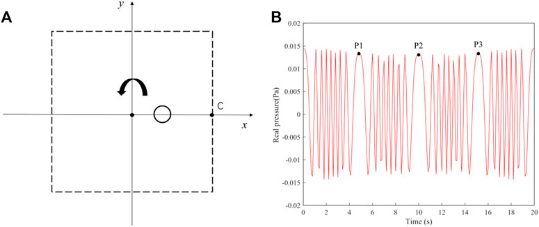
FIGURE 12. (A) The arrangement of measuring point. (B) The relationship between sound pressure and time at the point C.
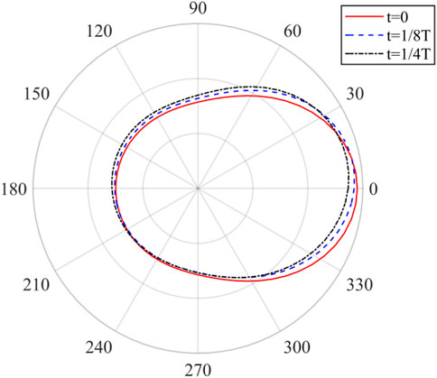
Figure 13 shows the directivity diagram of the acoustic scattering at three selected moments in a period of bubble movement when ka = 1. During the uniform circular motion of the bubble, the sound energy is mainly concentrated in the forward direction of the incident wave. Since the direction of motion about the bubble is counterclockwise, the acoustic directivity shifts upward with the bubble motion, but the offset angle θ is small. At the same time, the forward sound pressure slightly decreases and the backward sound pressure slightly increases, which shows the effect of the circular motion of the bubble on the sound field distribution.
To further discuss the effect of bubble circular motion on the sound field, the circumferential radius and angular velocity for bubble motion at θ = 1°, 5°, 10° at different kawere calculated. In Figure 14A, R is the radius of the bubble’s circular motion, and L is the distance between the measuring point and the bubble. At the same θ, the ka value increases and the circumferential radius required for bubble motion increases. When ka is fixed, the bubble’s circular motion radius increases proportionally with the increase of θ. This proves that the radius of circular motion of the bubble has a certain impact on far-field sound pressure, and the larger the radius of motion, the more significant the change in directionality.
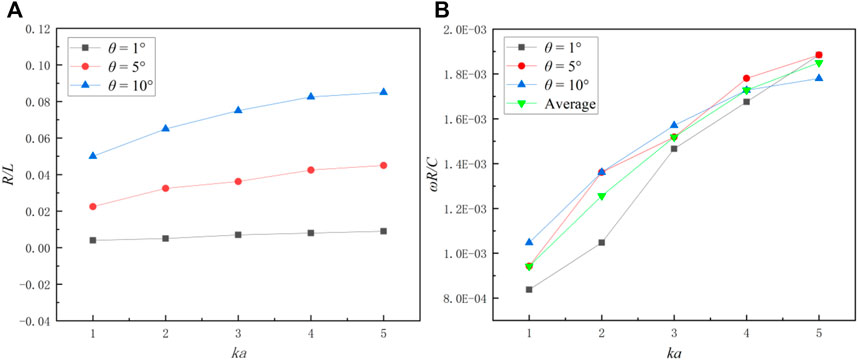
FIGURE 14. Relationship between the offset angle and circumferential radius (A) and angular velocity (B) during uniform circular motion at different ka values.
Figure 14B shows the relationship between the offset velocity of the acoustic directivity (w = 1°·s−1) and the angular velocity of the bubble (ω). When the ka value increases, the ω also increases. When ka is the same, the ω corresponding to different θ is not much different. Therefore, the average of the three angular velocities can be selected to represent the relationship between the w and the ω. It can be seen that within the same movement time, an increase in the velocity of the bubble’s circular motion will not cause a significant change in directionality. However, as ka increases, the bubble requires a greater circumferential velocity to shift the directionality of the sound by the same angle.
5.3 Small deformation bubbles
In reality, the bubble does not always keep spherical when moving, but deforms due to the pressure. The shape change of bubbles can be observed in Chapter 4. Therefore, this section discussed the property of acoustic scattering about ellipsoidal bubbles. The ratio of long and short axes of bubbles is defined as N = a/b, a is the long axes and b is the short axes. When N = 1, it represents an ideal spherical bubble. Figure 15 is the scattering directivity diagram of ellipsoid bubble at different N when ka = 1.
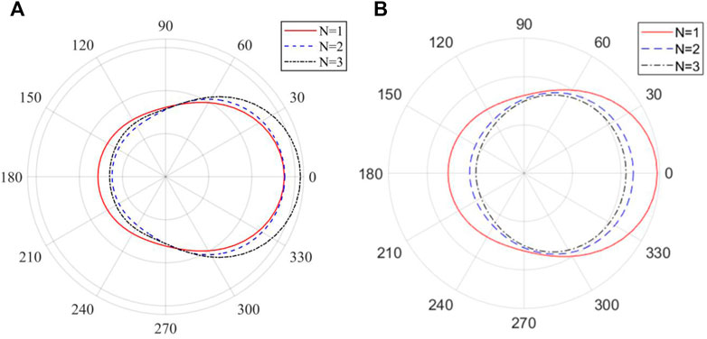
FIGURE 15. The relationship between the acoustic directivity of the ellipsoid bubble and the major and minor axes. (A) The bubble volume remains constant. (B) The long axis of the bubble remains constant.
Figure 15A shows that when the bubble volume keeps constant, as N increases, the long axis a of the bubble increases and the short axis b decreases, which indicates the shape of the bubble becomes more and more flat. During this change, the forward sound pressure increases and the backward sound pressure decreases. The energy of the acoustic scattering is also concentrated in the forward direction of the incident wave, and the amplitude of the sound pressure increases slightly. By comparing the calculated results in Figure 15A with the literature [37], it can be found that the scattered sound pressure of the bubble is close to the minimum value for N = 2. Figure 15B represents the bubble with a change in volume, its long axis a remains constant. As the short axis b decreases, the volume of the bubble decreases, the amplitude of scattered sound pressure decreases, and the directivity decreases This indicates that the decrease in bubble volume has a greater impact on sound radiation than the change in the long and short axes of the bubble on the scattered sound field. Comparing Figures 15A, B, it can be found that both the size and thickness of the bubble have an effect on the scattered sound field.
6 Conclusion
Regarding the problem of the sound radiation and scattering of moving bubbles, this paper introduces a coupled CFD-BEM method to predict the acoustic radiation and scattering of bubbles under low motion velocity. Based on the motion boundary of bubbles obtained by CFD, the BEM program is used to solve the acoustic radiation and scattering of stationary spherical and ellipsoidal bubbles, uniform linear rising bubbles, and uniform circular motion bubbles respectively. The following conclusions are obtained.
(1) ka has an important influence on the acoustic scattering of the bubble. When the ka value is small, the directivity of the acoustic scattering is not obvious. With the increase of ka value, the main lobe and side lobe appears, and the energy of the acoustic scattering is gradually concentrated in the forward direction of the incident wave.
(2) For a bubble moving in a straight line, the distance of moving can deflect the far-field acoustic directivity (The far field distance is about 100 m). For a bubble with circular motion, the radius of motion (R) is positively proportional to the acoustic directivity changing velocity (w).
(3) For the ellipsoidal bubble, the flatter the bubble, the higher its forward scattering sound pressure. It is worth noting that the shape and volume changes of the bubble can both affect the distribution of scattered sound field.
Data availability statement
The original contributions presented in the study are included in the article, further inquiries can be directed to the corresponding author.
Author contributions
Y-FL writing (original draft), methodology, theoretical model analysis and data. Y-OZ and TZ: idea, conceptualization, writing and reviewing of the manuscript, structural scheme design, theoretical model analysis, supervision and funding. YQ: investigation, review of the manuscript. All authors contributed to the article and approved the submitted version.
Funding
This study is supported by the Innovative Research Foundation of Ship General Performance of China (No. 33122233) and the Open Fund of Science and Technology on Thermal Energy and Power Laboratory (No. TPL2021B03).
Conflict of interest
The authors declare that the research was conducted in the absence of any commercial or financial relationships that could be construed as a potential conflict of interest.
Publisher’s note
All claims expressed in this article are solely those of the authors and do not necessarily represent those of their affiliated organizations, or those of the publisher, the editors and the reviewers. Any product that may be evaluated in this article, or claim that may be made by its manufacturer, is not guaranteed or endorsed by the publisher.
References
1. Rayleigh L. On the pressure developed in a liquid during the collapse of a spherical Cavity. Phil Mag J Sci (1917) 200(34):504–7. doi:10.1080/14786440808635681
2. Plesset MS. The dynamics of cavitation bubbles. J Appl Mech (1949) 3(16):277–82. doi:10.1115/1.4009975
3. Neppiras EA. Acoustic cavitation. Phys Rep (1980) 61(3):159–251. doi:10.1016/0370-1573(80)90115-5
4. Sreedhar BK, Albert SK, Pandit AB. Cavitation damage: Theory and measurements–A review. Wear (2017) 372:177–96. doi:10.1016/j.wear.2016.12.009
5. Wang SP, Zhang AM, Liu YL. Bubble dynamics and its applications. J Hydrodynamics (2018) 30(6):975–91. doi:10.1007/s42241-018-0141-3
6. Zhang AM, Li SM, Cui P. A unified theory for bubble dynamics. Phys Fluid (2023) 35:03323. doi:10.1063/5.0145415
7. Minnaert M. On musical air-bubbles and the sounds of running water. Phil Mag J Sci (1933) 16(104):235–48. doi:10.1080/14786443309462277
8. Zhang AM, Ming FR, Liu YL. Review on the researches on underwater explosion related to load characteristics, ship damage and protection. Chin J Ship Res (2023) 2023:1–16. doi:10.19693/j.issn.1673-3185.03273
9. Wang PP, Zhang AM, Peng YX. Numerical simulation of transient strongly-nonlinear fluid-structure interaction in near-field underwater explosion based on meshless method. Chin J Theoret Appl Mech (2022) 54(8):2194–209. doi:10.6052/0459-1879-22-271
10. Hu ZY, Cao ZE, Li S. Fluid-structure interaction between a high-pressure pulsating bubble and a floating structure. Chin J Theoret Appl Mech (2021) 53(4):944–96. doi:10.6052/0459-1879-20-357
12. Kundu T, Bostrom A. Axisymmetric scattering of a plane longitudinal wave by a circular crack in a transversely isotropic solid. J Appl Mech (1991) 58(3):695–702. doi:10.1115/1.2897250
13. Chinnery PA, Humphrey VF, Beckett C. The schlieren image of two-dimensional ultrasonic fields and cavity resonances. J Acoust Soc Am (1997) 101(1):250–6. doi:10.1121/1.417976
15. Shi XG, Zhao GJ, Wu YY. CFD simulation of bubbles behavior in baffled bubbling fluidized bed. Act Petrol Sin (2020) 36(01):113–20. doi:10.3969/j.issn.1001-8719.2020.01.014
16. Gao H, Xu HT. Computing T matrix of sound scattering by object using the boundary integral equation method. Act Acust (2008) 33(5):396–401. doi:10.15949/j.cnki.0371-0025.2008.05.002
17. Waterman PC. New formulation of acoustic scattering. J Acoust Soc Am (1969) 45(6):1417–29. doi:10.1121/1.1911619
18. Marburg S, Nolte B. Computational acoustics of noise propagation in fluids: Finite and boundary element methods. Berlin: Springer (2008). p. 411—434.
19. Feuillade C. Acoustically coupled gas bubbles in fluids: Time-domain phenomena. J Acoust Soc Am (2001) 109(6):2606–15. doi:10.1121/1.1369102
20. Burgschweiger R, Schäfer I, Mohsen A. Results of an implementation of the dual surface method to treat the non-uniqueness in solving acoustic exterior problems using the boundary element method. J Acoust Soc Am (2013) 19(1):065060. doi:10.1121/1.4799569
21. Chen IL, Chen JT, Kuo SR. A new method for true and spurious eigensolutions of arbitrary cavities using the combined Helmholtz exterior integral equation formulation method. J Acoust Soc Am (2001) 109(3):982–98. doi:10.1121/1.1349187
22. Fan LX. Research on calculation method of acoustic scattering characteristics of underwater moving sphere. China: Huazhong Univ Sci Technol (2018). p. 06.
23. Liu J, Wang W, Chu N. Numerical simulations and experimental validation on passive acoustic emissions during bubble formation. Appl Acoust (2018) 130:34–42. doi:10.1016/j.apacoust.2017.09.005
24. Zhang Y, Dang S, Li W. Performance of the radial point interpolation method (RPIM) with implicit time integration scheme for transient wave propagation dynamics. Comput Math Appl (2022) 114:95–111. doi:10.1016/j.camwa.2022.03.031
25. Cong SH. Study on bubble flow field and radiated sound characteristics. China: Shandong Univ (2022). doi:10.27272/d.cnki.gshdu.2022.002821
26. Li Y, Liu C, Li W. Numerical investigation of the element-free Galerkin method (EFGM) with appropriate temporal discretization techniques for transient wave propagation problems. Appl Math Comput (2022) 442:127755. doi:10.1016/j.amc.2022.127755
27. Li W, Zhang Q, Gui Q. A coupled FE-Meshfree triangular element for acoustic radiation problems. Int J Comput Methods (2021) 18(03):2041002.
28. Hirt CW, Nichols BD. Volume of fluid (VOF) method for the dynamics of free boundaries. J Comput Phys (1981) 39(1):201–25. doi:10.1016/0021-9991(81)90145-5
29. Du H, Xiong AK, Zhang YO. Forward sound scattering from an underwater vortex. J Acous (2020) 45(01):55–61. doi:10.15949/j.cnki.0371-0025.2020.01.006
30. Liu WT, Gui Q, Jiang HY. Application of boundary element coupling radial basis point interpolation meshless method in acoustic scattering. Ship Sci Technol (2023) 45(2):02–7. doi:10.3404/j.issn.1672-7649.2023.02.026
31. Williams EG. Fourier acoustics: Sound radiation and nearfield acoustical holography. United States: Acad Press (2000). doi:10.1016/B978-0-12-753960-7.X5000-1
33. Jamali J, Honarvar F, Naei MH. Acoustic wave scattering from infinite cylinders made from functionally graded materials. J Acoust Soc Am (2008) 123(5):3277. doi:10.1121/1.2933624
34. Zhang Y, Yang F. Numerical simulation of single bubble floating process. Mod Manufacturing Technol Equip (2016) 07:4–7. doi:10.16107/j.cnki.mmte.2016.0523
35. Li S, Zhang AM, Sun LQ. Dynamic behavior of rising bubble. Acta Phys Sin (2014) 63(18):291–303. doi:10.7498/aps.63.184701
36. Hua J. Study on the dispersion characteristics of sound velocity in media containing bubbles. China: Harbin Eng Univ (2018). p. 01.
Keywords: moving bubble, computational fluid dynamics, boundary element method, acoustic scattering, acoustic radiation
Citation: Li Y-F, Zhang Y-O, Qu Y and Zhang T (2023) A numerical approach for acoustic radiation and scattering of moving bubbles at low frequencies. Front. Phys. 11:1191160. doi: 10.3389/fphy.2023.1191160
Received: 21 March 2023; Accepted: 17 May 2023;
Published: 30 May 2023.
Edited by:
Feiyan Cai, Chinese Academy of Sciences (CAS), ChinaReviewed by:
Ould El Moctar, University of Duisburg-Essen, GermanyA-Man Zhang, Harbin Engineering University, China
Copyright © 2023 Li, Zhang, Qu and Zhang. This is an open-access article distributed under the terms of the Creative Commons Attribution License (CC BY). The use, distribution or reproduction in other forums is permitted, provided the original author(s) and the copyright owner(s) are credited and that the original publication in this journal is cited, in accordance with accepted academic practice. No use, distribution or reproduction is permitted which does not comply with these terms.
*Correspondence: Yong-Ou Zhang, emhhbmd5b0B3aHV0LmVkdS5jbg==
 Yi-Fan Li
 Yong-Ou Zhang
 Yao Qu
 Tao Zhang2