 Shibing Lin
 Deen Wang
 Yamin Zheng
 Liquan Guo
 Yifan Zhang
 Yongchen Zhuang
 Lei Huang
- 1Key Laboratory of Photonic Control Technology (Tsinghua University), Ministry of Education, Beijing, China
- 2Department of Precision Instrument, Tsinghua University, Beijing, China
Helicity and topological charge are two important characteristic parameters for vortex beam applications, including optical communications, optical manipulation and material processing, etc. In this work, a helicity and topological charge tunable vortex laser based on a folded resonant cavity is presented. In the resonant cavity, a Z-shaped structure is adopted and two deformable mirrors (DMs) are cascaded into the cavity as intro-cavity modulation elements. By applying different voltage combinations to the DMs, the Hermite-Gaussian (HG) beam with different indices and distribution orientations
1 Introduction
Vortex beam with the helical phase in the form of
The generation of the helicity and TC tunable vortex beam has been widely studied and various methods have been reported [4–15]. One of the most direct methods is to generate a helicity and TC tunable vortex beam from a resonant cavity with intra-cavity modulation. By introducing helicity and TC selection elements into a resonant cavity, such as two nanowires [4], a YAG crystal [5], a quarter-wave plate [6], a black phosphorus plate [7], etc., the vortex beam with controllable helicity (left/right) and the TC (up to ±
Apart from the mentioned methods obtaining the target vortex beam directly with intra-cavity modulation, the extra-cavity conversion based on the Hermite-Gaussian (HG) beam could also be used to generate the TC and helicity tunable vortex beam. The conversion elements, such as spiral phase plate (SPP) [10–12], spatial light modulation (SLM) [13–15] and digital micro-mirror device (DMD) [16, 17], could convert a fundamental mode beam to the vortex beam with target TCs and helicity. However, the SPP is customized and a SPP could only convert the fundamental mode HG beam to one type of vortex beam. Thus, a large amount of customized SPPs is needed to achieve different kinds of TC and helicity. For the SLM/DMD conversion, the vortex beam with target TCs and helicity could be realized by loading special computer-generated holograms. However, the energy loss of these diffractive optical elements is inevitable in the conversion process, which limits their application in the high-power laser field. Besides the mentioned elements, the extra-cavity astigmatic mode converter (AMC) could convert a
In this paper, a vortex laser that could flexibly generate the TC and helicity tunable vortex beam is reported. In the presented vortex laser, two cascaded deformable mirrors (DM), a single-piezoelectric (PZT) DM and a multi-PZT DM, are set as the intra-cavity modulation elements in a Z-shaped folded resonant cavity. Through loading different driving voltage combinations to the DMs, different surface shapes are generated and the intra-cavity mode is modulated. Thus, the HG beam in the form of
2 Methods
Figure 1 shows the schematic diagram of the proposed vortex laser, which mainly contains a Z-shaped LD-pumping laser and a conversion and recognition module. In the Z-shaped LD-pumping laser, the pumping beam emitted from a fiber-coupled LD (20W, 976nm, 0.22NA/105 µm core diameter, BWT Beijing LTD.) is focused into a gain medium GM (Yb: CALGO, 5 a. t.%, a-cut, 2 mm
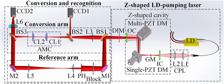
FIGURE 1. Schematic diagram of the TC and helicity tunable vortex laser.
In the conversion and recognition module, the incident HG beam is converted to the corresponding LG beam in the conversion arm, while a reference beam used to recognize the converted LG beam is obtained in the reference arm. The conversion arm is composed of three beam splitters (BS1: transmittance and reflectance ratio TRR of 1:9@1064nm, BS2 and BS3: TRR of 1:1@1064 nm), a matching lens L3 (175 mm focal length), and an AMC (two identical cylindrical lenses CL1 and CL2, both 25 mm in focal length). The BS1 splits part of the HG beam generated from the Z-shaped laser into the reference arm as an input. L3 focuses the incident HG beam into the AMC to satisfy the AMC conversion condition [18]. The BS2 splits part of the HG beam into CCD1 (Point Grey, GS3-U3-14S5M) and the corresponding intensity pattern is recorded. After the AMC conversion, the converted LG beam is reflected by BS3 and focused by L6 (30 mm focal length) into CCD2 (Point Grey, GS3-U3-14S5M). Note that the intensity pattern of the converted LG beam will be recorded by CCD2 when only the LG beam incident into CCD2. The reference arm consists of two reflection mirrors (M1 and M2: HR@1064 nm/45°), a switch block, a pinhole PH (2 mm-diameter hole), and a telescope system (L4 and L5, focal length of 25mm and 125 mm). The block has two states of “on/off” and determines whether the HG beam is allowed to enter into the reference arm. Lenses L4 and L5 are set non-confocal. When the block is in the state of “on,” a spherical reference beam will be generated based on the small central part of the incident beam that passes through the PH. The interference fringe of the spherical reference beam and the vortex beam is recorded by CCD2. Thus, the helicity and TC of the vortex beam will be recognized.
Two cascaded DMs, including a single-PZT DM and a multi-PZT DM, are adopted in the vortex laser. Figure 2 shows the outside views, section views and constraints of the two DM mirrors. From Figure 2B, it could be seen that the single-PZT DM consists of a mirror, a pillar, a steel base, an adhesive, a PZT and a preload screw. The multi-PZT DM [shown in Figure 2E] shares the same basic structure of the single-PZT DM, except that it contains an additional post and has 9 PZTs. The distances between two adjacent PZTs along X and Y-axes are both 8 mm in the multi-PZT DM. Figures 2C, F show the mirror constraints of the DMs, which could be divided into assembly constraints and structural constraints. The assembly constraints [disp, disx and disy in Figures 2C, F] represent the location relationship among the pumping beam, the gain medium and the center of the mirror. The constraints of mirror structure shown in Figures 2C, F contain the fixed area, the PZT area and the free area. It should be noted that the numbers 0–9 in Figures 2C, F represents the corresponding PZT. The simulation models of the DMs are built [22]. Figure 3 shows the simulation results of the surface shapes of the two cascaded DMs with 10 V driving voltage of typical PZTs, including PZT 0 of the single-PZT DM, PZTs 1, 2 and 5 of the multi-PZT DM. The simulated influence functions (IF, surface shape with PZT driving voltage of 1 V) of PZT 0–9 could be calculated. Thus, the surface shapes
where
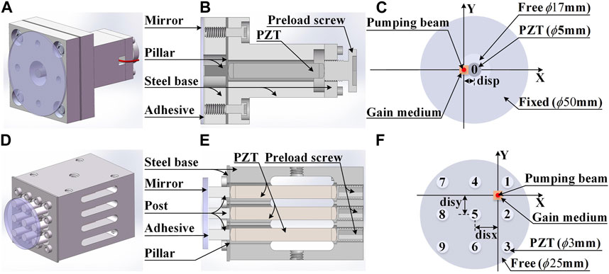
FIGURE 2. Outside views (A, D), section views (B, E) and constraints of the mirrors (C, F) of two cascaded DMs.
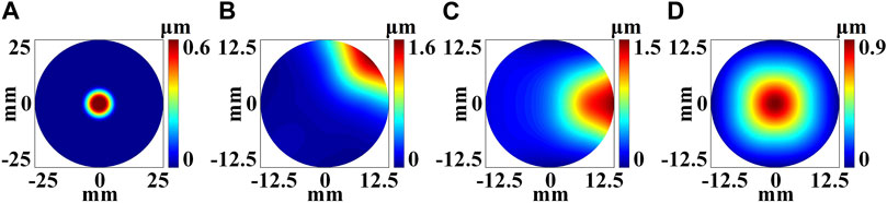
FIGURE 3. Surface shapes of two cascaded DMs with 10 V driving voltage of typical PZTs. PZT 0 (A) of the single-PZT DM. PZT 1 (B), 2 (C) and 5 (D) of the multi-PZT DM.
In the Z-shaped resonant cavity, the surface shape distributions of DMs could be adjusted by loading different PZT voltages according to Eq. 1, and the surface shape distributions of DMs will introduce an additional phase into the intra-cavity propagation light field to realize intra-cavity modulation [23]. Due to the Single/Multi-PZT DMs are cascaded and various intra-cavity modulation conditions could be produced by adjusting PZT voltages, when the intra-cavity modulation of a tilt HG mode is satisfied, a tilt HG mode could be generated and the rotation of HG beam is realized. Thus, a mode-tunable
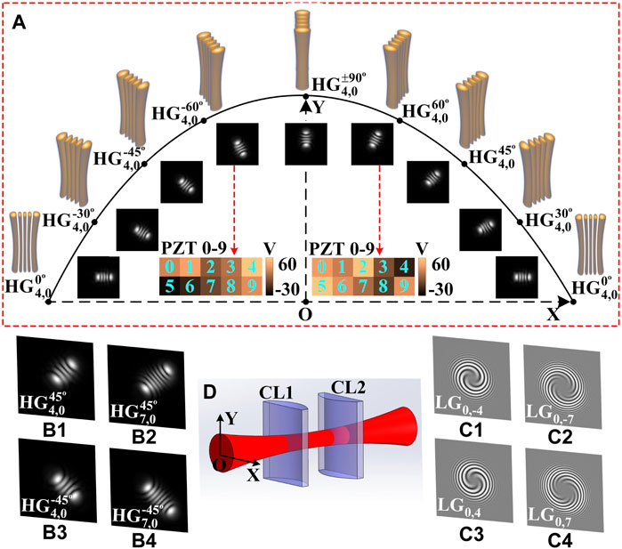
FIGURE 4. Simulation results of the TC and helicity tunable vortex laser. (A) 3D beam propagation and intensity patterns of
3 Results and discussion
3.1 Simulation results
To verify the feasibility of the proposed vortex laser, a numerical simulation is carried out based on the mode modulation regulation of the vortex beam [23]. In the simulation, structure parameters of the Z-shape cavity (Figure 1) are set as follows: the distance between IC and the right surface of the GM is 6mm; the distance between the left surface of the GM and the single-PZT DM is 46mm; the distance between the cascaded DMs is 30 mm; the distance between the multi-PZT DM and OC is 25 mm; the assembly constraints (disp, disx and disy) of the DMs are 3.5 mm, 0 mm and 3 mm.
3.2 Experiment results
Figure 5 shows the experimental setup of the TC and helicity tunable vortex laser. In the experiment, all the parameters of the Z-shaped LD-pumping laser are the same as the simulation. Before loading driving voltages to the DMs, the Z-shaped LD-pumping laser is first precisely adjusted to obtain the fundamental mode at the pumping current of 1.3 A (maximum current of the LD is 7.5 A in our setup). Figure 6 displays the experiment results. In the experiment, the distribution orientation
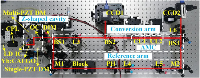
FIGURE 5. Experimental setup of the TC and helicity tunable vortex laser.
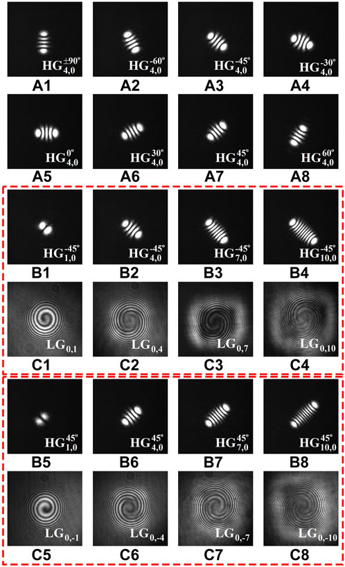
FIGURE 6. Experiment results of the TC and helicity tunable vortex laser. (A1–A8)
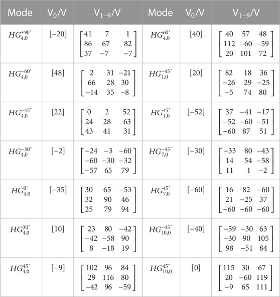
TABLE 1. Driving voltage combinations corresponding to the experiment results in Figure 6.
According to the simulation and experiment results, the HG beam could be rotated from −90 to 90° in the vortex laser, which reduces the assembly requirements of the orientation of the AMC to convert the HG beam to the LG beam. Two kinds of HG beams with orthogonal distribution orientations could always be achieved by selecting suitable driving voltage combinations to generate helicity and topological charge tunable vortex beams based on AMC conversion. The distribution directions of HG beams could be expressed by
The method could avoid the complex mechanical off-axis adjustment in [15] and could flexibly generate the TC and helicity tunable vortex beam by loading suitable driving voltage combination of DMs. Most importantly, higher order topological charge is possible by optimizing the driving voltage combinations. Note that a complex multiple-PZT DM could realize the function of the cascaded DMs in this work, but the requirements of the multiple-PZT DM will be more complex and the cost will increase. The cascaded DMs adopted here could shape the laser modes with decreased requirement and cost.
4 Conclusion
In conclusion, a TC and helicity tunable vortex laser based on a Z-shaped resonant cavity and an extra-cavity AMC, is proposed. This laser adopts two cascaded DMs, a single-PZT DM and a multi-PZT DM, as the intra-cavity modulation elements in the Z-shaped resonant cavity. The HG beam in the form of
Data availability statement
The original contributions presented in the study are included in the article/supplementary material, further inquiries can be directed to the corresponding author.
Author contributions
SL and LH contributed to conception and design of the study. SL performed the simulation and the experiment. SL, LH, DW, YZ, LG, YFZ, and YGZ contributed to writing and editing the manuscript. All authors contributed to the article and approved the submitted version.
Funding
This work was supported by the National Natural Science Foundation of China (No. 61775112).
Conflict of interest
The authors declare that the research was conducted in the absence of any commercial or financial relationships that could be construed as a potential conflict of interest.
Publisher’s note
All claims expressed in this article are solely those of the authors and do not necessarily represent those of their affiliated organizations, or those of the publisher, the editors and the reviewers. Any product that may be evaluated in this article, or claim that may be made by its manufacturer, is not guaranteed or endorsed by the publisher.
References
1. Wang J. Advances in communications using optical vortices. Photon Res (2016) 4:B14–B28. doi:10.1364/PRJ.4.000B14
2. Dasgupta R, Ahlawat S, Verma RS, Gupta PK. Optical orientation and rotation of trapped red blood cells with Laguerre-Gaussian mode. Opt Express (2011) 19:7680. doi:10.1364/OE.19.007680
3. Toyoda K, Takahashi F, Takizawa S, Tokizane Y, Miyamoto K, Morita R, et al. Transfer of light helicity to nanostructures. Phys Rev Lett (2013) 110:143603. doi:10.1103/PhysRevLett.110.143603
4. Lin D, Daniel JMO, Clarkson WA. Controlling the handedness of directly excited Laguerre–Gaussian modes in a solid-state laser. Opt Lett (2014) 39:3903. doi:10.1364/OL.39.003903
5. Cao X, Liu Y, Xian A, Li Y, Wu K, Xu X, et al. Direct generation of ultrafast vortex beam from a Tm:CaYAlO 4 oscillator featuring pattern matching of a folded-cavity resonator. Opt Express (2021) 29:39312. doi:10.1364/OE.437584
6. Liu Q, Zhao Y, Zhou W, Zhang J, Wang L, Yao W, et al. Control of vortex helicity with a quarter-wave plate in an Er:YAG ceramic solid state laser. IEEE Photon J (2017) 9:1–8. doi:10.1109/JPHOT.2016.2644965
7. Liu Q, Zhang B, Qi S, Li Y, Fan X, Zhao Y, et al. Integration of helicity-control and pulse-modulation for vortex laser based on a black phosphorus plate. Opt Express (2016) 24:30031. doi:10.1364/OE.24.030031
8. Zhao Y, Liu Q, Zhou W, Shen D. ∼1 mJ pulsed vortex laser at 1645 nm with well-defined helicity. Opt Express (2016) 24:15596. doi:10.1364/OE.24.015596
9. He H-S, Chen Z, Li H-B, Dong J. Low-threshold, nanosecond, high-repetition-rate vortex pulses with controllable helicity generated in Cr,Nd:YAG self-Q-switched microchip laser. Laser Phys (2018) 28:055802. doi:10.1088/1555-6611/aaad4c
10. Khonina SN, Kotlyar VV, Shinkaryev MV, Soifer VA, Uspleniev GV. The phase rotor filter. J Mod Opt (1992) 39:1147–54. doi:10.1080/09500349214551151
11. Kotlyar V, Kovalev A, Porfirev A, Kozlova E. Orbital angular momentum of a laser beam behind an off-axis spiral phase plate. Opt Lett (2019) 44:3673–6. doi:10.1364/OL.44.003673
12. Khonina SN, Podlipnov VV, Karpeev SV, Ustinov AV, Volotovsky SG, Ganchevskaya SV. Spectral control of the orbital angular momentum of a laser beam based on 3D properties of spiral phase plates fabricated for an infrared wavelength. Opt Express (2020) 28:18407–17. doi:10.1364/OE.396199
13. Semmler M, Berg-Johansen S, Chille V, Gabriel C, Banzer P, Aiello A, et al. Single-mode squeezing in arbitrary spatial modes. Opt Express (2016) 24:7633. doi:10.1364/OE.24.007633
14. Li R, Ren Y, Liu T, Wang C, Liu Z, Zhao J, et al. Generating large topological charge Laguerre–Gaussian beam based on 4K phase-only spatial light modulator. Chin Opt Lett (2022) 20:120501. doi:10.3788/COL202220.120501
15. Ando T, Ohtake Y, Matsumoto N, Inoue T, Fukuchi N. Mode purities of Laguerre–Gaussian beams generated via complex-amplitude modulation using phase-only spatial light modulators. Opt Lett (2009) 34:34–6. doi:10.1364/OL.34.000034
16. Ren Y-X, Li M, Huang K, Wu J-G, Gao H-F, Wang Z-Q, et al. Experimental generation of Laguerre-Gaussian beam using digital micromirror device. Appl Opt (2010) 49:1838. doi:10.1364/AO.49.001838
17. Chen Y, Fang Z-X, Ren Y-X, Gong L, Lu R-D. Generation and characterization of a perfect vortex beam with a large topological charge through a digital micromirror device. Appl Opt (2015) 54:8030–5. doi:10.1364/AO.54.008030
18. Abramochkin E, Volostnikov V. Beam transformations and nontransformed beams. Opt Commun (1991) 83:123–35. doi:10.1016/0030-4018(91)90534-K
19. Beijersbergen MW, Allen L, van der Veen HELO, Woerdman JP. Astigmatic laser mode converters and transfer of orbital angular momentum. Opt Commun (1993) 96:123–32. doi:10.1016/0030-4018(93)90535-D
20. Wang D, Wang D, Wang D, Lei M, Lin S, Lin S, et al. Generation of a mode-tunable optical vortex based on a mirror curvature dynamically controlled Z-shaped resonant cavity. Opt Lett (2021) 46:3079–82. doi:10.1364/OL.422316
21. Shen Y, Meng Y, Fu X, Gong M. Wavelength-tunable Hermite–Gaussian modes and an orbital-angular-momentum-tunable vortex beam in a dual-off-axis pumped Yb:CALGO laser. Opt Lett (2018) 43:291. doi:10.1364/OL.43.000291
22. Zheng Y, Lei M, Lin S, Wang D, Xue Q, Huang L. Filtered influence function of deformable mirror for wavefront correction in laser systems. Photonics (2021) 8:410. doi:10.3390/photonics8100410
Keywords: helicity, topological charge, vortex beam, deformable mirror, Hermite-Gaussian
Citation: Lin S, Wang D, Zheng Y, Guo L, Zhang Y, Zhuang Y and Huang L (2023) Helicity and topological charge tunable optical vortex based on a Hermite-Gaussian beam dynamically controlled folded-cavity resonator. Front. Phys. 11:1192257. doi: 10.3389/fphy.2023.1192257
Received: 23 March 2023; Accepted: 03 May 2023;
Published: 23 May 2023.
Edited by:
Rumao Tao, China Academy of Engineering Physics, ChinaReviewed by:
Hongfei Jiao, Tongji University, ChinaYuxuan Ren, Fudan University, China
Shijun Zhu, Nanjing University of Science and Technology, China
Copyright © 2023 Lin, Wang, Zheng, Guo, Zhang, Zhuang and Huang. This is an open-access article distributed under the terms of the Creative Commons Attribution License (CC BY). The use, distribution or reproduction in other forums is permitted, provided the original author(s) and the copyright owner(s) are credited and that the original publication in this journal is cited, in accordance with accepted academic practice. No use, distribution or reproduction is permitted which does not comply with these terms.
*Correspondence: Lei Huang, aGxAdHNpbmdodWEuZWR1LmNu