 Leehwan Hwang1
 Seunghyun Lee2*
- 1Department of Immersive Content Convergence, Kwangwoon University, Seoul, Republic of Korea
- 2Ingenium College, Kwangwoon University, Seoul, Republic of Korea
We propose a holographic printing–recording technology for near-eye display through volume holographic grating analysis in hologram recording and reconstruction. Most near-eye displays are designed based on waveguide-type and analog holographic optical elements, resulting in disruption of the uniformity of the image because of the difference between the initial recording conditions and the source image. This problem can be addressed using holographic printing technology to modulate different diffraction efficiencies for each holographic element. This study uses a digital HOE screen that can fabricate and reconstruct augmented reality images of 1.17”, 1.76”, and 2.35” in a field of view of 28.07°, 41.11°, and 53.13°, respectively, at a distance of 53.33 mm from the eye. Moreover, augmented images are realized with higher diffraction efficiency than conventional methods, simplifying the design and facilitating mass production of uniformed products using digital holographic printing technology.
1 Introduction
AR has gained widespread adoption in various industries, including gaming, education, healthcare, and manufacturing industries. Near-eye displays, such as smart glasses and headsets, have become more accessible and affordable, driving their increased usage. In particular, in the field of research on the development of optical devices, a lot of research is being conducted in the AR display field [1, 2]. There have been significant improvements in the optics of AR and near-eye displays [3]. Enhanced display resolutions, wider field of view (FOV), and improved image quality have resulted in more immersive and realistic AR experiences. Advancements in waveguide and diffractive optics have enabled sleeker designs and reduced the form factor of near-eye displays. This enables lightweight and portable designs. Manufacturers are focusing on creating lightweight and portable AR and near-eye display devices. These advancements enhance user comfort, enabling extended usage periods and making them suitable for various applications, including enterprise, entertainment, and consumer markets. A near-eye display (NED) with a transparent waveguide is one of the promising devices for this field [4, 5]. This type of NED can be divided into three main parts—the display source image, the in-coupler that can relay the source image to total internal reflection (TIR), and the out-coupler that transfers the relayed image information to the eye [6, 7]. These couplers typically comprise a diffractive optical element (DOE) and volume holographic grating (VHG). The DOE forms an angle of refraction by etching a grating on a material such as glass or plastic, and VHG is an optical element in which grating is applied to a medium using holography. Using these elements, a portable NED system can be designed to be lightweight and compact and is, therefore, extensively studied by suppliers like Microsoft, Meta, and Digilens that develop potable head-mounted display (HMD) devices such as augmented reality (AR) glass [8–10]. A waveguide-type NED system generally provides a field of view (FOV) of approximately 50°–54° [11, 12]. This factor prevents users from immersing themselves in realistic AR content because of the inconsistency of focus between the virtual image and the real world. However, in this case, it is a factor that provides a sufficiently large volume to be applied to a portable terminal. Even for portable devices, these factors can facilitate a large system volume. In the case of the DOE, the wavelengths of red, green, and blue for full-color display can cause color dispersion like a rainbow between diffraction angles as the direction of light is determined by the shape and distance of the grating pattern. This can be solved using a holographic optical element (HOE). In the case of the HOE, the propagation direction of light is determined by the spacing between grating patterns like the DOE. However, if the same wavelength as the hologram recording condition is used, multiple spots do not occur, and there is no chromatic aberration. However, uniformity cannot be guaranteed as the system is fabricated by an analog hologram recording method. Moreover, when the specifications change, the optical system must be redesigned, which is time consuming and expensive [13, 14]. In this paper, we propose optimal recording conditions by analyzing the selectivity and efficiency of images according to the digital hologram recording method by a waveguide-type NED system. Analog hologram recording refers to the traditional method of capturing and storing holographic information using optical techniques. In this process, a coherent light source, such as a laser, is split into two beams: the reference beam and the object beam. The object beam is directed toward the object or scene being recorded, and the scattered light from the object interacts with the reference beam to create an interference pattern. This interference pattern is captured on a holographic film or plate, which preserves the complex wavefront information of the object. On the other hand, digital hologram recording involves the use of digital sensors, such as charge-coupled devices (CCDs) or complementary metal-oxide-semiconductor (CMOS) cameras, to directly capture the interference pattern. Instead of using photographic film, the interference pattern is recorded as a series of intensity values or complex amplitudes, forming a digital hologram. The digital hologram can then be stored, processed, and reconstructed using computational algorithms. For this reason, with digital hologram recording methods, we can utilize various numerical computations on a computer to achieve the desired results. In addition, to improve the uniformity of AR images restored through the HOE, we present an optimized digital HOE recording method that uses holographic printing technology and a computer-generated hologram (CGH) pattern to control the varying diffraction efficiency for each holographic element (hogel) as a minimum recording unit.
Consequently, the proposed VHG recording method is proved to be effective in uniformly displaying AR contents of a large screen with reconstructed depth images from NED.
2 Methods
We use NED based on an HOE in this system. This system uses an HOE fabricated using holography as a screen. Therefore, an image focused at a close position in front of the eye is positioned at a deep position through the HOE screen having optical refractive power. This enables observers to enjoy comfortable video viewing and reduces the gap between the augmented video and the real world. Therefore, the depth of the image depends on the focal length of the HOE, and the FOV is related to the size of the screen and the focal length of the HOE. Therefore, when transmitting an image in a system using a waveguide, the size of the screen reflecting the image and the transmission angle determine the FOV of the system and the depth of the image. To transmit optical information using total reflection, Figure 1A shows the hologram recording method used for in-coupled HOE. Covestro’s photopolymer was selected as the holographic material. Air, photopolymer, and waveguide glass have different refractive indexes. Therefore, the TIR angle at the final input spot must be an acceptable critical angle value that can satisfy the condition. When we see the top left image in Figure 1A, the angle
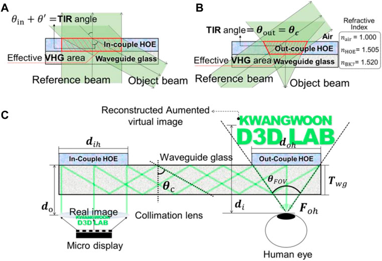
FIGURE 1. (A) Recording ray diagram for the in-coupled HOE. (B) Recording ray diagram for the out-coupled HOE. (C) Reconstructed AR virtual image from the holographic waveguide system.
In Figure 1A, the refractive index of the photopolymer should be considered because the object beam passes through the photopolymer and is incident on the glass. We denote this deviation value as
Figure 2A shows the results of measuring the intensity by dividing each HOE into areas to verify the uniformity of 10 cm2, 15 cm2, and 20 cm2. The angles and intensities of the incident light for each area on the HOE surface are indicated. Through this simulation, it is observed that although the hologram is recorded using the entire surface of the HOE, the efficiency varies due to the different angles at which light illuminates the HOE surface for incoming spherical waves, such as in the case of the NED system. The focal length of the out-coupled HOE is defined as the TIR angle at which light enters at a 45° angle in a linear space, converging to a unit angle. Although the distance of the input image incident on the HOE is the same, different sizes of HOEs result in obtaining FOVs of 28.07°, 41.11°, and 53.13° for 10 cm2, 15 cm2, and 20 cm2, respectively. Therefore, as can be seen from the simulation results, as the size of the out-coupled HOE increases, the converging angle toward the eye also increases. Thus, a large HOE designed to reconstruct an image with a large FOV will be created as a hologram with different diffraction efficiencies, as shown in the simulation results. Therefore, in order to compensate for the diffraction efficiency that varies with these angles, we record each area of the HOE surface using different optical powers for each area and perform angular compensation. As a result, the final reconstructed image can be uniformly restored. When recording holograms for HOE fabrication, we need to calculate the angular selectivity to determine the power. If the angular selectivity is large, it will accept a large amount of light, and if it is small, it will accept a small amount of light. The calculation is determined based on Eq. 1 [15]. This equation is based on Herwig Kogelnik’s coupled wave theory and explains the influence of the tilted grid in light’s Bragg diffraction in holographic restoration on the angle and wavelength sensitivity. FOVs of 28.07°, 41.11°, and 53.13° can be obtained. To select the reconstruction efficiency for each recording angle, which is different for each unit, as a compensation value, the HOE is recorded by the conventional analog method. Efficiency was measured for each unit by dividing the entire effective area into six regions and measuring the reconstructed beam diffracted in each area. The angle in the space of the straight line incident to the out-coupled HOE at 45°, which is the TIR angle, and the straight line where each unit converges as the focal length is defined as
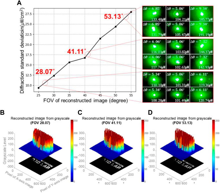
FIGURE 2. (A) Comparison of intensity for reconstructed images according to FOVs. (B) Angular distribution at 28.07° FOV. (C) Angular distribution at 41.11° FOV. (D) Angular distribution at 53.13° FOV.
For
Figure 3A shows the optical schematic for holographic printing. The two beams from the laser are divided into a reference beam and an object beam, respectively, using a beam splitter. The reference beam is incident at 45°, which is equal to the TIR angle in the NED. The object beam passes through a spatial filter consisting of an objective lens and a pinhole. The passing beam is incident on the spatial lighting modulator (SLM) using the collimated beam through the lens. This SLM has a resolution of 4,096 × 2,160 with a pixel size of 4 μm and generates a diffractive beam by modulating an incident collimated beam with a CGH generation pattern transmitted from a PC. Furthermore, it modulates each
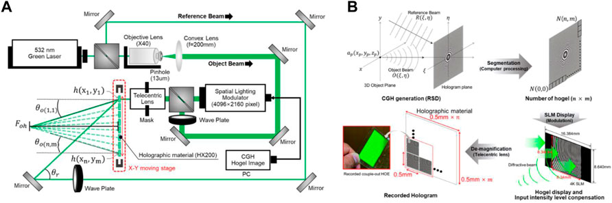
FIGURE 3. (A) Optical schematic of the holographic printing system. (B) Process of CGH generation and recording.
The reciprocal (wavenumber)
The CGH pattern produced using the aforestated formula is divided into
3 Results and discussion
Figure 4A shows the result of illuminating the reference light after printing without compensation for deviation in a general printing method. The deviation between the center and edge areas was severe at 53.15° rather than at the narrowest FOV of 28.07°. The average FOV efficiency decreased by 52.70%, 81.67%, and 92.34% in the order of 28.07°, 41.11°, and 53.13°, respectively. When we see the result of Figure 4A, it is evident that the three HOEs exhibit a decrease in surface uniformity. The central region of the HOEs shows an average power ranging from 200 uW to 240 uW, while the outermost region demonstrates a significant drop, reaching values below 40 uW. This indicates a reduction in output by more than 90%, highlighting the insufficient ability of the entire HOE surface to reproduce images uniformly. However, the improved HOEs, utilizing the proposed method, demonstrate a deviation in output degradation of less than 10% between the central and outermost regions. This showcases higher uniformity compared to images reproduced using conventional hologram recording methods.
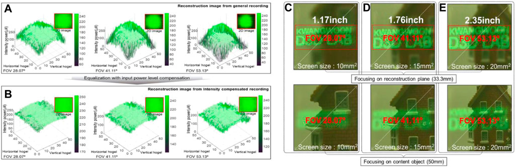
FIGURE 4. (A) Out-coupled HOE recorded with the general printing method. (B) Out-coupled HOE printed by compensating for the diffraction efficiency for each hogel angle. (C) Reconstructed image with 28.07° FOV and 10 mm2 size of the out-coupled HOE. (D) Reconstructed image with 41.11° FOV and 15 mm2 size of the out-coupled HOE. (E) Reconstructed image with 53.13° FOV and 20 mm2 size of the out-coupled HOE.
Figure 4B shows the result of recording each hogel using varying light quantity, considering the aforementioned deviation. The image is an augmented image seen at the observer’s position when the green image was input as the source image, and the uniformity of the intensity distribution of the reconstructed image was analyzed by standardizing it to 255 levels. Figure 4B shows an entirely uniform result, unlike Figure 4A. Figure 4C shows the result of image reconstruction with the HOE recorded as a result of angle compensation using holographic printing technology. The HOE can be adjusted by using the CGH pattern to set the distance between the 3D object
4 Conclusion
We developed a uniform reconstruction method of the HOE screen by applying the holographic printing–recording technology as the HOE recording method of the NED system that fabricates compact and large FOV images. CGH was applied to the design of the in-coupler and out-coupler devices while developing the analog-type NED system for digital HOE printing. This showed the possibility of producing spherical and aspherical high-resolution optical devices using a holographic printing system with a stage. In addition, system imperfections caused by manual setup can be solved. However, several problems are yet to be solved. Although the problem of reconstruction efficiency caused by the incidence on the HOE screen at different recording angles during recording has been solved, as the size of the hogel cannot be made infinitely small, the limitation of resolution and reconstruction error caused by the fine boundary should be considered. If these problems are solved in the future, thin-film high-wide-angle refractive aspherical elements with the aforementioned advantages can be manufactured. This may lead to the development of portable devices that implement immersive AR content, such as HMD and head-up display manufacturing fields.
Data availability statement
The original contributions presented in the study are included in the article/Supplementary Material; further inquiries can be directed to the corresponding author.
Author contributions
All authors listed have made a substantial, direct, and intellectual contribution to the work and approved it for publication.
Funding
This work was supported by the Institute of Information and Communications Technology Planning and Evaluation (IITP) grant funded by the Korean government (MSIT) (No. 2020-0-00922, Development of holographic stereogram printing technology based on multi-view imaging); the Institute of Information and Communications Technology Planning and Evaluation (IITP) grant funded by the Korean government (MSIT) (No. 2020-0-01846, Research and development of realistic content device technology); the Ministry of Culture, Sports, and Tourism; and the Korea Creative Content Agency (Project No. R2021040083). The present research was conducted by the excellent researcher support project of Kwangwoon University in 2022.
Conflict of interest
The authors declare that the research was conducted in the absence of any commercial or financial relationships that could be construed as a potential conflict of interest.
Publisher’s note
All claims expressed in this article are solely those of the authors and do not necessarily represent those of their affiliated organizations, or those of the publisher, the editors, and the reviewers. Any product that may be evaluated in this article, or claim that may be made by its manufacturer, is not guaranteed or endorsed by the publisher.
References
1. Albakri G, Bouaziz R, Alharthi W, Kammoun S, Al-Sarem M, Saeed F, et al. Phobia exposure therapy using virtual and augmented reality: A systematic review. Appl Sci (2022) 12:1672. doi:10.3390/app12031672
2. Dibbets P, Schruers K. An online spider game: Overcome your fear, exposure is near. Comput Hum Behav Rep (2022) 6:100201. doi:10.1016/j.chbr.2022.100201
3. Balyk N, Grod I, Vasylenko Y, Shmyger G, Oleksiuk V. The methodology of using augmented reality technology in the training of future computer science teachers. Int J Res E Learn (2021) 7:1–20. doi:10.31261/ijrel.2021.7.1.05
4. Ko SH, Rogers J. Functional materials and devices for XR (VR/AR/MR) applications. Adv Funct Mater (2021) 31(39):2106546. doi:10.1002/adfm.202106546
5. Cheng D, Liu Y, Wang Q, Hou W, Yang T, Feng Z, et al. Optical design and pupil swim analysis of a compact, large EPD and immersive VR head mounted display. Opt Express (2022) 30(5):6584–602. doi:10.1364/oe.452747
6. Piao J-A, Li G, Piao M-L, Kim N. Full color holographic optical element fabrication for waveguide-type head mounted display using photopolymer. J Opt Soc Korea (2013) 17(3):242–8. doi:10.3807/josk.2013.17.3.242
7. Yoo C, Bang K, Chae M, Lee B. Extended-viewing-angle waveguide near-eye display with a polarization-dependent steering combiner. Opt Lett (2020) 45(10):2870. doi:10.1364/ol.391965
8. Rosilius M, Eitzen IV, Wilhelm M, Schmitt J, Engelmann B, Bräutigam V. Evaluation of visual requirements and software-design for immersive visibility in industrial applications. IEEE ISAR-Adjunct (2021) 21414661.
9. Colburn M. Fundamental challenges in augmented reality display technology. IEEE IEDM (2020) 20548659.
10. Waldern JD, Grant AJ, Popovich MM. 17-4: DigiLens AR HUD waveguide technology. SID Int Symp Dig Tech Pap (2018) 49(1):204–7. doi:10.1002/sdtp.12523
11. Zhang Q, Piao Y, Ma S, Liu Y, Wang Y, Song W. Design, analysis and optimization of a waveguide-type near-eye display using a pin-mirror array and a concaved reflector. Opt Express (2022) 30(18):33208. doi:10.1364/oe.469828
12. Lin Y, Xu H, Shi R, Lu L, Zhang ST, Li D. Enhanced diffraction efficiency with angular selectivity by inserting an optical interlayer into a diffractive waveguide for augmented reality displays. Opt Express (2022) 30(17):31244. doi:10.1364/oe.469126
13. Hwang LH, Hur GT, Kim JH, Gentet P, Kwon SC, Lee SH. Uniformity improvement of a reconstructed-holographic image in a near-eye display system using off-axis HOE. Opt Express (2022) 30(12):21439. doi:10.1364/oe.460680
14. Hwang LH, Jeong JH, Go CY, Gentet P, Kim JH, Kwon SC, et al. Verification of polarization matching on the hologram recording plane for the implementation of an optimized digital hologram printing system. Front Phys (2022) 10:857819. doi:10.3389/fphy.2022.857819
15. Kogelnik H. Coupled wave theory for thick hologram gratings. IEEE Xplore Bell Syst Tech J (1969) 30(9):2909–47. doi:10.1002/j.1538-7305.1969.tb01198.x
16. Grüneis A, Shepherd JJ, Alavi A, Tew DP, Booth GH. Explicitly correlated plane waves: Accelerating convergence in periodic wavefunction expansions. J Chem Phys (2013) 139:084112. doi:10.1063/1.4818753
17. Heßelmann A, Jansen G, Schütz M. Density-functional theory-symmetry-adapted intermolecular perturbation theory with density fitting: A new efficient method to study intermolecular interaction energies. J Chem Phys (2005) 122:014103. doi:10.1063/1.1824898
Keywords: holographic optical element, volume Bragg grating, near-eye display, holographic printing, photopolymer volume hologram
Citation: Hwang L and Lee S (2023) Development of holographic printed HOE recording technology with VHG-based FOV analysis for waveguide-type NED system. Front. Phys. 11:1201420. doi: 10.3389/fphy.2023.1201420
Received: 06 April 2023; Accepted: 05 June 2023;
Published: 16 June 2023.
Edited by:
Xiangang Luo, Chinese Academy of Sciences (CAS), ChinaReviewed by:
Lingling Huang, Beijing Institute of Technology, ChinaGuoxing Zheng, Wuhan University, China
Copyright © 2023 Hwang and Lee. This is an open-access article distributed under the terms of the Creative Commons Attribution License (CC BY). The use, distribution or reproduction in other forums is permitted, provided the original author(s) and the copyright owner(s) are credited and that the original publication in this journal is cited, in accordance with accepted academic practice. No use, distribution or reproduction is permitted which does not comply with these terms.
*Correspondence: Seunghyun Lee, c2hsZWVAa3cuYWMua3I=