 Sara Casalbuoni1*
 Suren Abeghyan1
 Levon Alanakyan1Johann Baader1Serena Barbanotti2
 Winfried Decking2Massimiliano Di Felice1Hans-Jörg Eckoldt2
 Uwe Englisch1Gianluca Geloni1
 Vanessa Grattoni1
 Andreas Grau3Axel Hauberg2Christian Helwich2Achim Hobl4Kay Jensch2
 Suren Karabekyan1Daniele La Civita1Sven Lederer2Christoph Lechner1Lutz Lilje2
 Shan Liu2
 Barbara Marchetti1Andrew Potter5Tobias Schnautz2Evgeny Schneidmiller2Harald Sinn1Wolfgang Walter4
 Riko Wichmann2Torsten Wohlenberg2Grigory Yakopov1
 Mikhail Yakopov1Igor Zagorodnov2René Zimmermann2Pawel Ziolkowski1
- 1European X-ray Free-Electron Laser Facility, Schenefeld, Germany
- 2Deutsches Elektronen-Synchrotron, Hamburg, Germany
- 3Karlsruhe Institute of Technology, Karlsruhe, Germany
- 4Bilfinger Noell GmbH, Wurzburg, Germany
- 5University of Liverpool, Liverpool, England
For more than 5 years, superconducting undulators (SCUs) have been successfully delivering X-rays in storage rings. The European X-Ray Free-Electron Laser Facility (XFEL) plans to demonstrate the operation of SCUs in X-ray free-electron lasers (FELs). For the same geometry, SCUs can reach a higher peak field on the axis with respect to all other available technologies, offering a larger photon energy tunability range. The application of short-period SCUs in a high electron beam energy FEL > 11 GeV will enable lasing at very hard X-rays > 40 keV. The large tunability range of SCUs will allow covering the complete photon energy range of the soft X-ray experiments at the European XFEL without changing electron beam energy, as currently needed with the installed permanent magnet undulators. For a possible continuous-wave (CW) upgrade under discussion at the European XFEL with a lower electron beam energy of approximately 7–8 GeV, SCUs can provide the same photon energy range as available at present with the permanent magnet undulators and electron energies. This paper will describe the potential of SCUs for X-ray FELs. In particular, it will focus on the different activities ongoing at the European XFEL and in collaboration with DESY to allow the implementation of SCUs in the European XFEL in the upcoming years.
1 Introduction
Storage rings and free-electron lasers (FELs) make use of undulators to deliver highly brilliant photon beams to a vast user community. Undulators are special magnets consisting of an array of dipoles that produce a sinusoidal magnetic field. Undulators emit radiation at specific wavelengths λn:
where λU is the undulator period, n = 1,2,3,... is an integer describing the harmonic number, and γ is the Lorentz factor. K is the “so-called” undulator parameter, e is the electron beam charge, B is the peak magnetic field on the axis, me is the electron mass, and c is the speed of light. Most of the undulators used nowadays are based on permanent magnet technology. As shown in Equation (1), in order to reduce the photon wavelength/increase the photon energy without increasing the electron beam energy at a fixed peak magnetic field on axis B, the undulator period λU needs to be reduced. On the other hand, for the same technology and geometry, by reducing λU, the peak magnetic field on axis B and, therefore, the tunability range (the available photon energy range) are also decreased.
Different efforts have been made in the past decades to reduce the period of the undulators while keeping a high magnetic field on axis B. Figure 1 shows the evolution of these efforts. On the top left is sketched a permanent magnet undulator (PMU) with the magnet arrays out of the vacuum chamber. The first step has been the inclusion of the magnetic arrays inside the electron beam vacuum chamber. In this way, the magnets are closer to the electron beam, which, therefore, is subject to a higher magnetic field. These are the “so-called” in-vacuum undulators (IVUs). The second step consisted in cooling the magnetic arrays in the IVUs. By cooling the magnets to approximately 100 K, their remanence increases and so does the peak field on the magnetic axis. These are the “so-called” cryogenic permanent magnet undulators (CPMUs). In order to further increase the peak field on the axis, superconducting magnet technology has been applied. Superconducting undulators (SCUs) have dipole arrays made of superconducting coils cooled down to approximately 4 K.
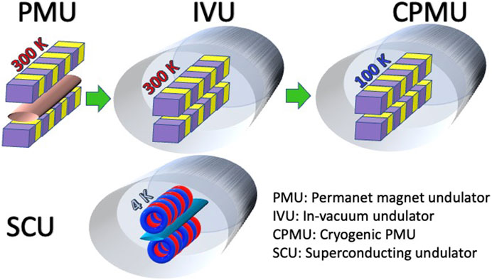
FIGURE 1. Top: sketches of the evolution of permanent magnet undulator technology to achieve a higher magnetic peak field on the magnetic axis. Bottom: a sketch of NbTi superconducting undulator technology, which allows to further improve the peak field on the magnetic axis with respect to the one that is PMU-based.
A comparison in terms of peak field on the magnetic axis between the aforementioned technologies is shown in Figure 2. A beam stay clear/vacuum gap of 5 mm has been considered. The curves reported in Figure 2 are obtained by the following parametrization curves. For the magnetic field on axis B (T) of the PMUs and IVUs with, respectively, a magnetic gap g of 7 mm and 5.2 mm, the following function [1] is considered:
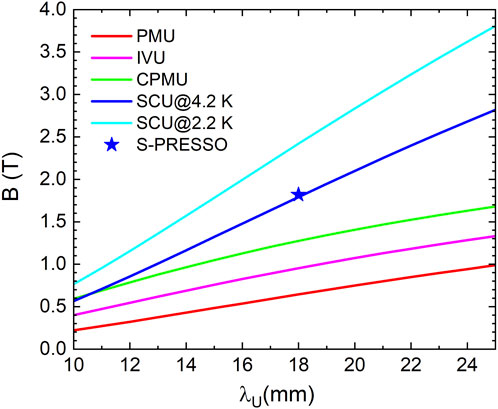
FIGURE 2. Comparison in terms of the magnetic field as a function of the undulator period at a beam stay clear/vacuum gap of 5 mm for different undulator technologies sketched in Figure 1. The peak field on the magnetic axis of S-PRESSO is also shown.
The magnetic field of the CPMUs with g = 5.2 mm is described by [2].
The one for the SCUs is described by [3].
where λU and g are in mm and B is in T. The blue curve shown in Figure 2 for SCUs is valid by operating at a temperature of 4.2 K with a temperature margin of 1 K for both of the following cases: a) a magnetic gap of 6 mm applying ≈80% of the critical current and b) a magnetic gap of 6.5 mm applying ≈85% of the critical current. The last one, which is the case for S-PRESSO, the first SCU to be installed at the European XFEL, is described in Section 4. SCUs show potential to further increase their performance, as shown in the blue curve in Figure 2. This is possible by applying superconductors with higher critical temperatures and current densities, such as Nb3Sn or high-temperature superconducting tapes or bulks. Both technologies are not mature yet. Another possibility is to work with the well-proven technology based on the NbTi wire using a cooling scheme, allowing it to reach lower temperatures (the cyan curve in Figure 2). Applying superfluid helium cooling schemes as performed for the Nb superconducting radio frequency (RF) cavities improves the peak field on the axis by 35%. The cyan curve in Figure 2 is obtained by multiplying the right term of Equation (4) by 1.35. Simulations made with FEMM (http://www.femm.info/wiki/HomePage) confirmed this parametrization for 10, 15, 18, 20, and 25-mm period length SCUs with a magnetic gap of 6 mm and a temperature margin of 1 K.
An additional advantage of NbTi SCUs with respect to permanent magnet-based undulators is radiation hardness, which has been demonstrated in NbTi magnets used in different colliders such as the Tevatron [4], HERA [5], and LHC [6] for several decades.
The choice of the undulator period is driven by the selected photon energy range and can be made once the electron energy is fixed. To cover an even larger photon energy range, it is possible to 1) vary the electron beam energy, which is performed, for example, at the European XFEL and 2) use undulators with period doubling. These possibilities complicate the parameter space, and for the sake of simplicity, they should be kept as options and not as guiding lines. It should also be remembered that the large tunability range of the photon energy presents challenges for both the optics and the experimental techniques.
SCUs offer elegant solutions, using the same winding body, to duplicate or triplicate the period length, which can further increase the photon energy tunability range considerably [7].
SCUs based on NbTi coils have been serving users since more than 5 years at the Advanced Photon Source (APS) [8] and the Karlsruhe Institute of Technology (KIT) light source [9]. SCUs are now commercially available from the company Bilfinger Noell GmbH (BNG). A long-term development carried out at KIT in collaboration with the industrial partner BNG has led to the successful commercialization of SCUs [10]. Recently, an SCU produced by BNG and measured by KIT has been installed in the Australian Light Source [11].
It is now time to implement SCUs in FELs. The potential of SCUs for X-ray FELs is addressed in the following section. Afterward, the plans for implementing SCUs at the European XFEL and the ongoing activities necessary to realize them are described.
2 Superconducting undulators for X-ray free-electron lasers
In terms of cost reduction, the main advantage of using short-period and strong magnetic field undulators, such as SCUs, for an FEL with respect to PMUs, is that, to reach a defined photon energy, it is possible to reduce the electron beam energy.
In the case of an undulator with a shorter period but keeping the same K value, the saturation length is shorter, and consequently, the length of the undulator line is shorter. For a green field facility, this would result in considerable savings in civil construction costs.
Advantages of SCU over PMUs include the following:
• SCUs allow for building more compact and, therefore, less expensive FELs.
• For a given electron beam energy, SCUs allow to reach harder X-rays than PMUs, maintaining a larger tunability. This is because SCUs can reach higher peak fields for the same geometry.
• Due to the larger maximum peak magnetic field, SCUs offer wider photon energy tunability ranges than PMUs.
Currently, X-ray FELs use PMUs and IVUs. However, there are no plans, to the best of authors’ knowledge, to install CPMUs, SHINE, LCLS, and European XFEL working on the implementation of SCUs [12]. The Chinese CW X-ray FEL SHINE plans a complete undulator line with SCUs [13]. The LCLS facility is planning to install a cryostat with two 1.5-m-long SCU coils with a cold intersection in between consisting of a superconducting phase shifter, a copper quadrupole, and an RF cavity BPM [14]
SCUs are part of the European XFEL facility development program. The development of SCUs will enable us to build the know-how inside the facility for the state-of-the-art technology and further improve the know-how technology to be later transferred to industries. The benefits of SCUs to the European XFEL strategic plan are manifold:
• The European XFEL has the highest electron beam energy among all the similar facilities worldwide [15]. SCUs with a period between 15 and 20 mm, and a vacuum gap (magnetic gap) of 6 mm (7 mm) offer the possibility to establishing an FEL source above 30 keV toward 100 keV, which is unprecedented to date [16,17].
• The European XFEL has two hard undulator lines and one soft X-ray undulator line. In order to enable the complete photon energy range of 250 eV—3 keV for the experiments at the soft X-ray line with the present PMUs (period length = 68 mm; Kmax = 9), the electron beam energy has to be lowered to 8.5 GeV. On the other hand, the harder X-ray experiments benefit from the high electron beam energy (up to 17.5 GeV). The state-of-the-art SCU technology offers a solution to this challenge and allows reaching the required tunability with similar period lengths, as the present PMUs (∼ 70 mm).
• The European XFEL is currently running in the so-called burst mode, which provides trains with a maximum of 2,700 electron bunches spaced by 220 ns (4.5 MHz repetition rate) with a repetition rate of the trains of 10 Hz. A CW upgrade of the linac, similar to what will be supplied by SHINE and LCLS II, is under consideration. This upgrade includes a refurbishment of the cryogenic plant with the aim of approximately doubling its capacity and operation at a reduced electron beam energy of approximately 7–8 GeV. In order to cover a similar photon energy range as now covered with an electron beam energy of 17.5 GeV and the PMUs with a 40-mm period length, it would be necessary to use undulators with a shorter period length. SCUs with a period length between 15 and 20 mm will be able to cover the same photon energy range. Figure 3 shows the saturation length of SCUs with 18 mm and 15 mm period lengths as a function of the photon energy for an electron beam energy of 8 GeV, peak current = 5 kA, normalized emittance = 0.4 mm mrad, rms energy spread = 3 MeV, and horizontal and vertical beta functions βx = βy = 16 m. The solid lines indicate the photon energies reachable with an SCU operating at 4.2 K, while the dotted lines are those reachable with an SCU operating at 2.2 K, both with a 1-K temperature margin.
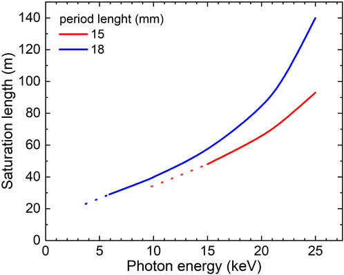
FIGURE 3. Saturation length for an SCU with an 18-mm period and Bmax = 1.82 T (blue line) and for an SCU with a 15-mm period and Bmax = 1.64 T (red line) as a function of the photon energy for an electron beam energy of 8 GeV, peak current = 5 kA, emittance = 0.4 mm mrad, energy spread = 3 MeV, and horizontal and vertical beta functions βx = βy = 16 m. The solid lines indicate the photon energies reachable with an SCU operating at 4.2 K, while the dotted lines are the photon energies reachable with an SCU operating at 2.2 K, both with a minimum temperature margin of 1 K.
3 FESTA: a superconducting undulator afterburner for the European XFEL
The European XFEL has three undulator lines serving seven instruments. There are two hard X-ray lines and a soft X-ray line named SASE1, SASE2, and SASE3, respectively. By changing the electron energy range between 8.5 GeV and 17.5 GeV and/or the undulator gap, the undulator lines can be tuned to cover the following photon beam energy ranges: 3.6–25 keV (SASE1/2) and 0.25–3 keV (SASE3).
A total of six SCU modules are planned to be installed downstream of the SASE2 PMUs at the European XFEL. The Superconducting undulator PRE-SerieS mOdule (S-PRESSO) is the pre-series module for the Free-Electron laser SuperconducTing undulator Afterburner (FESTA). More details on the design of S-PRESSO can be found in the following section. The small-series production FESTA consists of five modules.
A sketch of the SASE2 undulator line at the European XFEL showing the position of the planned six SCU modules is presented in Figure 4. The length of each SCU module cryostat is 5 m, identical to the length of the installed PMUs. This allows us to use the same intersections (violet rectangle).
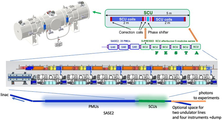
FIGURE 4. Layout of the SASE2 undulator line (bottom) indicating the downstream side (middle) with S-PRESSO and the planned FESTA SCU modules [16]. On the top, a sketch of each SCU module is shown with a 3D model of the cryostat.
Each intersection contains a quadrupole magnet to focus the electron beam transversely below ≈30 μm, which is necessary for the FEL process to take place; a beam position monitor and a beam loss monitor for electron beam diagnostics; air coils to trim the vertical and horizontal first and second field integrals of the undulators; and a phase shifter to compensate the phase advance of the emitted photons with respect to the electron beam. In the PMU lines, the intersections are 1.1 m long. An RF valve will be placed at the intersection separating the last PMU and the first SCU. The intersections interfacing with the SCUs also need to host RF bellows. The RF bellows permit vertical and horizontal alignment of the SCUs with beam and length compensation for the thermal shrinkage of the SCU modules after cooldown. Each SCU module will sit on four cam movers that are remotely controllable.
All SCU modules will be cooled with cryocoolers, following a cryogen-free conduction-cooled scheme similar to the one developed by the KIT/Bilfinger Noell collaboration. We are planning to use six cryocoolers per SCU module. Each SCU module contains two 2-m-long SCU coils with superconducting corrector coils co-wound at the last grooves of the iron yoke and two pairs of vertical and horizontal iron-free coils located between the main coils with a superconducting phase shifter between them (see the upper plot in Figure 4). The layout of each module is planned to be the same as the S-PRESSO module, and it is described in the following section.
Each intersection also contains an absorber to screen the downstream undulator from the radiation produced by the upstream undulators. The PMU vacuum chambers are elliptical with horizontal and vertical axes of 15 mm and 8.6 mm, respectively. The absorbers in the PMU line have a diameter of 8 mm. The SCU vacuum chamber has a racetrack shape with horizontal and vertical axes of 10 mm and 5 mm, respectively. Therefore, absorbers with a diameter of 4 mm are planned.
Simulations were run to estimate the heat load on the six SCU modules. The simulations were performed using BDSIM [18], a tracking code that also models the interactions between the particles and the beamline components. The simulation tracked the incoherent synchrotron radiation produced in SASE2 until after the SCU modules, simulated with SPECTRA. Some of this radiation is absorbed by copper absorbers and other beamline components during the simulation. The absorbers throughout SASE2 have an aperture of 8 mm. However, the absorber above the S-PRESSO module and all absorbers downstream of the S-PRESSO module have an aperture of 4 mm. The results of the simulation are used to estimate the rate at which energy is deposited into the SCU modules when the machine is running at full power. The results, reported in Figure 5, show that the maximum heat load is ≈ 0.1 mW, which does not affect the SCU module’s operation.
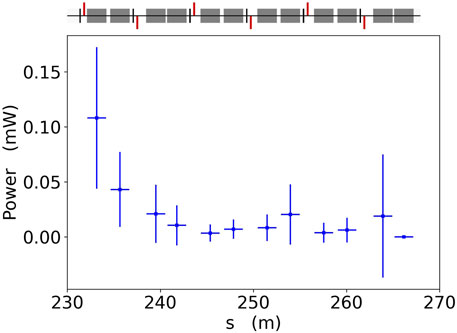
FIGURE 5. Power from the synchrotron radiation and its scattered particles deposited in the SCU coils of the six modules as a function of the longitudinal coordinates considering 4 mm diameter copper absorbers in the intersection between the last PMU and the first SCU and in between the SCUs.
A test 4-mm-diameter absorber has been installed downstream of the last PMUs of SASE2 in the winter shutdown of 2022/2023. The electron beam successfully passed through this test absorber. Radiation-sensitive detectors are placed downstream, and the effects of the radiation on the devices installed nearby are under investigation. The first results show low radiation levels.
The SCU coils are foreseen to have a period of 18 mm and a peak field on the axis of 1.82 T. We are mainly focusing on applications above 30 keV for electron beam energies > 16 GeV. S-PRESSO and FESTA can be operated by amplifying the first harmonic of the PMUs up to ≈40–50 keV. To reach higher photon energies, we planned to use the second harmonic bunching generated by the FEL process in the PMUs and amplify it with the fundamental of the SCUs. From first estimations, considering an electron beam energy of 16.5 GeV, a normalized emittance of 0.4 mm rad, and an initial energy spread of 3 MeV, the number of photons per pulse 30 fs long is ≳ 1010 up to ≈50 keV and > 109 at ≈ 60 keV [17]. Such values are up to two orders of magnitude larger than what can be reached in diffraction-limited storage rings such as the ESRF-EBS and APS-U [16]. Further studies, including wakefields, tapering, and optimized electron beam parameters, are foreseen. A promising way to generate brilliant photon beams at high energies is harmonic lasing [19]. A scheme using phase shifters and filters [20] for suppression of the fundamental is currently under numerical study. Experimental tests at low energies are also planned in the near future.
4 S-PRESSO: a pre-series module for FESTA
S-PRESSO is the pre-series module for FESTA. The technical requirements are reported in the study by [16] and summarized as follows. The main goals of S-PRESSO are to demonstrate the following:
• it is possible to contribute to the FEL process with such an SCU by reaching the needed accuracy in the alignment of the two 2-m-long SCU coils, and the mechanical manufacturing and assembly of the SCU coils;
• the feasibility of the implementation of such an SCU module in the accelerator in terms of interaction with the electron beam and space, utilities, and transport.
The contract of S-PRESSO has been assigned to Bilfinger Noell GmbH. The main parameters of the SCU coils of S-PRESSO are shown in Table 1. The peak fields on the axis and period have been chosen such that the fundamentals of the SCUs and SASE2 PMUs overlap at the high-photon-energy end of the SASE2 PMU tuning range. For example, for an electron beam energy of 16.5 GeV, the lowest photon energy of the fundamental of the SCUs is 25.3 keV and will overlap with the fundamental of the PMUs up to K ≈ 0.765, corresponding to 50 keV. As mentioned in Section 2, for the CW upgrade, it will be necessary to lower the electron beam energy to 7–8 GeV. For an electron beam energy of 8 GeV, the lowest photon energy of the fundamental of the SCUs is 5.9 keV and will overlap with the fundamental of the PMUs up to ≈ 11.8 keV.
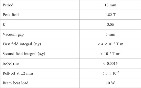
TABLE 1. Main parameters of S-PRESSO [16].
The main coils will be wound with a rectangular NbTi wire of 0.6 mm × 1 mm (bare dimensions). The wire has polyvinyl Formvar insulation with a thickness of 0.04 mm and 2,100 filaments with a diameter of 13 µm. All grooves are filled with 55 turns except the first and last three ones, which have a different winding scheme for end field compensation similar to the one used for the SCUs installed in the KIT and Australian light sources [10,11]. The geometry of a one-and-a-half period is shown in Figure 6.
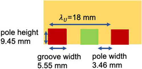
FIGURE 6. Sketch of the one-and-a-half period with dimensions of poles, grooves, and winding packages.
The upstream and downstream SCU coils will be powered by two power supplies up to a maximum current of 900 A. With 900 A of operating current, 2D and 3D magnetic field simulations produce a peak magnetic field on the axis that slightly exceeds the required 1.82 T. At a nominal current of 900 A, the conductor has a temperature margin of 1 K by operating at 4.2 K. To reduce the power consumption during operation, the power supplies will be placed in the tunnel close to S-PRESSO.
For the correctors and phase shifters, nine power supplies with 30 A and 40 V are foreseen. These are standard power supplies developed by the Deutsches Elektonen-Synchrotron (DESY) and used for the room temperature correctors of EuXFEL and PETRA III. The correctors and phase shifter will operate at a current of 10 A with a large temperature margin > 3 K.
The needed mechanical accuracies are reported in Table 2. They have been set considering that for the half periods, the following limits on K/2 hold: |∆K/K|rms < 0.0015 and |∆K/K| < 0.006. With the aforementioned restrictions on K/2, the pulse energy emitted by the six SCU modules is not significantly reduced [21]. FEL simulations show that the same requirements for mechanical accuracies are well-compatible with a complete SCU line with a 15-mm period length. Such mechanical accuracies reduce the mean FEL power at saturation length by less than 5% [22] and are, therefore, not notably harming the performance of the FEL process. In case that the magnetic field measurements show that the required mechanical accuracies/range of deviation of the undulator parameter are not reached in the manufacturing and assembly processes or are not maintained after cooldown, shim coils are foreseen.
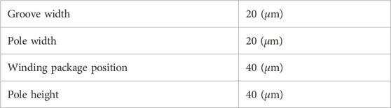
TABLE 2. Mechanical accuracies of the SCU coils [16].
The shim coils can be wound as racetracks (see the orange coil in Figure 7) with a thin NbTi wire with a diameter of 0.152 mm (insulated). Each shim coil wound around one pole can correct approximately 1% of the field with a current of 5 A. Using two neighboring shim coils with a pole in between and powered with 5 A, it is possible to correct up to 2% of the magnetic field. These values are sufficiently larger with respect to the maximum specified variations on the K-value. More configurations are studied and reported in [23]. A maximum of 11 power supplies of the same type as those for the corrector coils are foreseen for the shim coils.
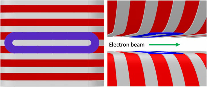
FIGURE 7. Sketch of a shim coil wound around one pole of the top and bottom SCU coils. Left: on the upper yoke. Right: on upper and lower yokes. Adapted from [29].
A misalignment between the two coils causes a correlated error in K-values along the magnetic axis. Calculations made by [22] show that for an SCU line, the two SCU coils in one module, as reported in Figure 8, need to be aligned with respect to each other within the values listed in Table 3. To fulfill the requirements on alignment, a rigid support structure, sustained by eight Ti rods, is designed to hold the SCU coils straight within 30 µm over a length of approximately 4.5 m. The magnetic gap is accessible at some places for coordinate measurement machine (CMM) measurements in assembled conditions. The alignment of the coils will be performed at room temperature and atmospheric pressure. The fiducialization procedure is foreseen to be performed as described in the study by [9].
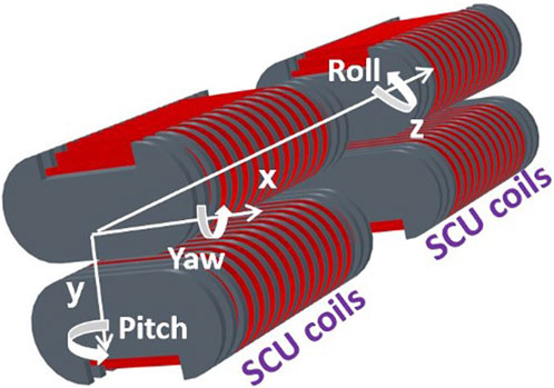
FIGURE 8. Sketch of the two SCU coils with the reference system defining the angles for the alignment constraints reported in Table 3 [29]. Reproduced under Creative Commons from Ref. [16].
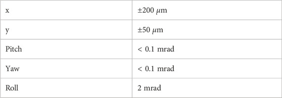
TABLE 3. Alignment requirements for the SCU coils [16].
A copper vacuum chamber separates the cold mass, placed in an insulation vacuum, from the electron beam vacuum. The racetrack chamber, with horizontal and vertical axes of 10 mm and 5 mm, respectively, will be 0.3 mm thick and will be made of copper with a residual-resistance ratio ≈100. The internal surface of the copper electron beam vacuum chamber must have a roughness Ra < 0.8 µm and an oxide layer thinner than 20 nm. In such conditions, the beam heat load due to resistive wall heating is always below 10 W for all relevant operation modes [16]. Geometric impedance will contribute to less than 0.1 W by keeping steps in the vacuum chamber cross-section < 0.1 mm. Synchrotron radiation will be screened by the copper absorbers placed in the upstream intersection (see Section 3).
A passive quench protection system in the form of cold rectifier diodes is foreseen. Each SCU single coil (top or bottom coil of one of the two SCU coils in the module) is protected by a set of six cold diodes, amounting to a total of 24 diodes for the two SCU coils. In case of a quench, the output of the power supply is deactivated via its interlock function, and the stored energy is dissipated within the coils and the diode racks. The quench detection is based on the balanced voltage principle. A quench is detected as soon as the difference between the voltages across the upper and lower coils increases above a certain threshold for longer than a given amount of time.
The cooling system is divided into two circuits: one for cooling the magnets and one for the vacuum chamber. S-PRESSO is cooled by six Gifford McMahon (GM) cryocoolers from Sumitomo: three are of type SRDE-412D4 with a cooling power of 1.25 W at 4 K and three are of type RDK-408S with a cooling power of 5.4 W at 10 K. The second stages of the three SRDE-412D4 cryocoolers are connected to the 4.2 K components, including the high-temperature superconducting current leads, while the three RDK-408S cryocoolers are connected to the electron beam chamber at approximately 10 K. The first stages of all six cryocoolers are used to intercept radiation on the thermal shield and the heat due to thermal conduction on the support rods, the electron beam chamber, and the resistive part of the current leads. The upstream and downstream SCU coils are powered by two power supplies through three current leads designed to operate at 900 A. This is of considerable advantage in terms of heat load and, therefore, needed cooling power compared to the normal design with four current leads carrying the operating current. The foreseen cooldown time is 7 days, and the warm-up time is 4 days.
5 SUNDAE test facilities
Two test facilities, SUNDAE1 [24] and SUNDAE2 [25] (Superconducting UNDulAtor Experiment), are under development to qualify the magnetic field properties of SCU coils. SUNDAE1 and SUNDAE2 are planned, keeping in mind the present needs for S-PRESSO and FESTA, and possible future upgrades of the European XFEL. SUNDAE1 is also foreseen to measure SCU test coils with novel winding schemes and superconducting wires and tapes carrying higher currents than NbTi, such as high-temperature superconducting (HTS) tapes (see Section 6). SUNDAE1 and SUNDAE2 are located at DESY in a hall with a cryoplant. Tests at 2 K are foreseen in SUNDAE1 and will be possible in SUNDAE2 with minor refurbishments of the helium distribution box. Measurements at 2 K might be of interest for possible future upgrades of the European XFEL, where complete SCU lines might be used. In such a case, cooling would be performed with a cryoplant instead of cryocoolers. To further improve the performance of the NbTi SCUs, similar solutions, as adopted for the superconducting RF cavity cryo-modules, could be used to cool the developed SCUs to 2 K (see Figure 2).
Both test stands will use their own in-house developed control systems, specifically based on Beckhoff Automation components and PLC software frameworks, as well as .NET applications. Data from the experiments will be stored in the InfluxDB database. Real-time visualization of time series will be performed via the Grafana web-based framework (see https://grafana.com/) connected to a database. Data analysis, such as calculating field integrals, will be performed via in-house developed software.
5.1 SUNDAE1
SUNDAE1 is a vertical cryostat to test SCU coils up to 2 m long in liquid and superfluid helium at 4 K and 2 K, respectively. The cryostat, previously used for tests of superconducting RF cavities, has a fixed helium level (≈2.4 m) and is being equipped with a new lid produced by the company Cryovac. The cryostat is directly connected to the cryoplant through a distribution box that can provide helium at two temperature levels: 4–5 K and 70–80 K. SUNDAE1 is additionally connected to pump stations to allow pumping of the helium bath down to ≈30 mbar (≈2 K). A liquid nitrogen supply line and a gas nitrogen return line are employed to cool the thermal shield and the magnet current leads.
SUNDAE1 is planned to perform training on the SCU coils and measure their magnetic field profile along the magnetic axis. The Hall probes will be mounted on a sledge moving along rails machined with high precision. The sledge is shown in Figure 9. The sledge is connected through a Ti rod to a linear motion system (see Figure 10) produced by Hositrad (https://www.hositrad.com/), with a single-axis vertical translator with a 2.4 m travel range and resolution, accuracy, and repeatability of 1 µm. The rod is located in a bellows, allowing a long motion range. We foresee two Hall probes from Areopoc calibrated at KIT at 4.2 K. The calibration error of the Hall probes is ±0.1 mT.
FIGURE 9. Sledge placed in precisely machined rails hosting the Hall probes to measure the magnetic field profile of planar SCU coils in SUNDAE1.
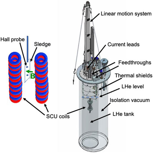
FIGURE 10. Model of SUNDAE1 (right) with a sketch of the sledge attached to a rod with Hall probes sliding along the magnetic field axis of the SCU coils (left).
The lid is equipped with four current leads to carry a maximum current of 1000 A, four current leads for 500 A, and 12 current leads for 20 A. Two bipolar power supplies with ± 1500 A and six power supplies with 20 A, with respective quench detectors, are being procured from JEMA (https://www.jemaenergy.com/). It is possible to power coils with a maximum current of 3000 A.
The temperature at the different stages of the current leads will be measured by Pt100 and Cernox temperature sensors and read out on five Lakeshore 224 monitors with 12 channels.
To locate possible quenches, five Cronosflex HISO-8 isolated amplifier modules (https://www.imc-tm.com/products/daq-systems/imc-cronosflex/overview/) with 40 channels (8 channels each) simultaneously readable with a maximum sampling rate of 2000 kS/s (max 50 kS/s per channel), to be connected to voltage taps on SCU coils, have been procured. The data acquisition is started by a trigger coming from a quench detector. A typical acquisition time scale is 1.5 s, including a pre-trigger time of 0.5 s. To read out the signals, the program imc STUDIO (https://www.imc-tm.com/products/measurement-software/imc-studio/overview/) is used.
The S-PRESSO and FESTA SCU coils, as well as the Helmholtz correction coils and phase shifter, will be tested in SUNDAE1. After quality assurance tests, they will be assembled in the final cryostat. Before the installation of S-PRESSO and FESTA modules in the tunnel, they will be characterized in SUNDAE2.
5.2 SUNDAE2
SUNDAE2 is a horizontal test stand to qualify SCU coils in their final cryostat. A sketch of SUNDAE2 is presented in Figure 11. The vacuum chambers at the two ends of the SCU modules are connected to the electron beam chamber.
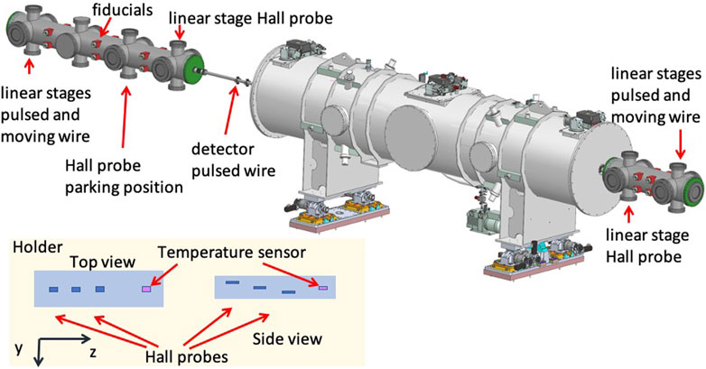
FIGURE 11. Model of SUNDAE2, including the UHV chambers with the magnetic measurement systems and S-PRESSO. Bottom left: top and side view of the holder for the three Hall probes (one 3-axis Hall magnetometer) and a temperature sensor.
A similar system, as in SUNDAE1, is foreseen for training the coils and performing quench analysis; this includes eight Cronosflex HISO-8 isolated amplifier modules with eight channels each for a total of 64 channels.
A stretched wire will be implemented. This will be used as a moving wire to measure the first and second field integrals and as a pulsed wire to measure the magnetic field longitudinal profile. The pulsed wire measurements will be dominated by dispersion. Such a measurement, in vacuum, on a magnetic length > 4 m with a period length as small as 18 mm, has never been performed before. A code was developed at the EuXFEL to correct for dispersion, finite pulse width, discretization errors, and sag [26]. Several steps to test the measurement technique are foreseen prior to the final characterization of S-PRESSO. The pulsed wire technique is extremely appealing for small apertures, as is the case for our SCU modules.
Given the extremely small dimensions of the S-PRESSO and FESTA module vacuum chambers, the Hall probe measurement is particularly challenging. Our approach is to use four Hall probes mounted on a ceramic holder tightly fitting the vacuum chamber. The longitudinal position of the Hall probes can be measured using an interferometer and a retroreflector placed on one side of the holder. The interferometer is planned to be installed on an optical table placed outside of the UHV chamber, close to the flange on the right side of Figure 11. The interferometer allows us to measure the relative longitudinal position with a precision of 1 µm. With such a holder, the transverse position of the Hall samples along the longitudinal axis cannot be determined with the required precision < 100 µm. The horizontal position is not critical since a good field region of ±2 mm is foreseen (see the roll-off in Table 1). To determine the magnetic field in the middle of the gap, three Hall probes need to be used at a distance along y of ≈100–200 µm, one from the other (see the reference system displayed in Figures 8, 11). In this way, considering the vertical transverse dependence of the magnetic field,
It will be possible to fit the measured field at each longitudinal position with Equation (5) and find the magnetic field value B at the minimum, corresponding to the middle of the gap. By measuring the field profile with the three Hall probes, it is possible to identify a set of three field measurements corresponding to the same longitudinal position. The distance in y between the three Hall probes can be determined by placing the holder with the Hall probes in a calibration setup. A room-temperature dipole is available at the European XFEL for this purpose. A goniometer with translation stages is being procured with a cold finger to hold the Hall probes. The typical calibration error obtained with Aeropoc Hall probes measured at KIT at 4.2 K, 30 K, and 77 K is ±0.4 mT. The expected error in determining B is approximately ±1mT, as shown in the example reported in Figure 12. To correct for possible deviations of the Hall probes’ position from being perpendicular to the magnetic axis, we foresee including an embedded 3-axis Hall magnetometer MagVector™ MV2 from Metrolab (https://www.metrolab.com/products/magvector-mv2/). Along axis z, the Hall probes will be at different temperatures. These will be determined during the first cooldown using a temperature sensor placed on the same holder as the Hall probes (see Figure 11).
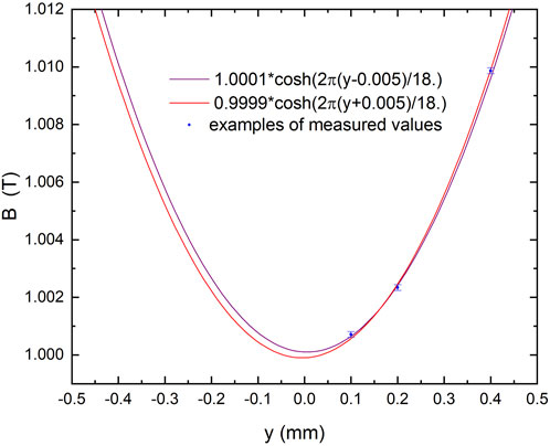
FIGURE 12. Typical measurement data set (blue dots) for the magnetic field at a specific longitudinal position. The two lines represent curves in Equation 5 with minimum and maximum fitting values for B.
The Hall probes will be calibrated at different temperatures in the range 4–100 K. We expect this to be the Hall probes temperature range while measuring the magnetic field profile along the axis z. Some of the planned Hall probes have been calibrated at KIT at 4.2 K, 30 K, and 77 K. The difference in the calibration curves at these temperatures is ±0.1 mT in the range of ±2 T.
It is clear that with the Hall probe method, we are following the middle of the gap and not the electron beam motion. The alignment of the upstream and downstream SCU coils can be tested only with the pulsed wire method since it relies on a tensed wire.
6 Advanced SCU coils
To improve the undulator’s performance, Nb3Sn or HTS materials like rare earth barium copper oxide (ReBCO) instead of NbTi superconductors can be utilized. These materials have higher irreversibility fields, critical temperatures, and critical current densities. The field quality of an SCU is strongly determined by the mechanical accuracies reached. Although Nb3Sn requires heat treatment, which reduces the reachable mechanical accuracies, this is not the case for ReBCO tapes, making them a good candidate for undulator applications.
Companies producing ReBCO tapes have made important improvements in the past few years to increase the engineering current density by doping ReBCO tapes with Zr and reducing the thickness of the substrate from 50 μm to 30 µm. This increases the reachable peak field on the axis even further. Once uniformity, repeatability, mechanical properties, available length, and production rate of high-quality ReBCO tapes are improved, ReBCO tapes will become the working horse to produce full-scale length magnets, including undulators, to be reliably operated in storage rings and FELs.
The best performance in terms of peak field on the axis can be reached by filling the SCU grooves with the HTS tape, taking advantage of the high engineering current density. The peak field on the axis can be increased by a factor of ≈ 1.7 with respect to NbTi by using the same geometry and the 11-K temperature margin operating at 4 K. This is reached with a current density of 5000 A/mm2 in the HTS tape. The values of the critical current have been obtained from the high-temperature superconducting wire critical current database maintained by the Victoria University of Wellington, Australia [27]. However, HTS tapes are not yet available in long lengths (the maximum length is approximately 100 m), and they are roughly 10 times more expensive than the NbTi wire. To use the high engineering current density of the ReBCO tape in the most effective location to increase the peak field on the magnetic axis, HybriSCU, a graded SCU combining NbTi and the ReBCO tape, has been proposed and studied. The concept foresees winding the first layers in the SCU grooves with the NbTi wire and the last layers closer to the electron beam with the ReBCO tape. An additional advantage of placing the ReBCO tape closer to the electron beam is its high temperature margin.
The geometry taken into consideration foresees the use of the 4-mm HTS tape and an undulator period of 16.8 mm. The improvement of Bmax at 16.8 mm for a magnetic gap of 6 mm and a temperature margin of 1 K for NbTi and 11 K for the ReBCO tape is approximately 15% by adding seven layers of the ReBCO tape to the 15 layers of NbTi and approximately 37% by considering 13 layers of NbTi and 30 layers of the ReBCO tape [28]. Further studies on the realization process of HybriSCU and ReBCO coils are planned.
7 Conclusions and outlook
Superconducting undulators are successfully operated in synchrotron light sources. The European XFEL plans to demonstrate the FEL process with S-PRESSO, a pre-series superconducting undulator, and provide photons for users with S-PRESSO and FESTA in the unexplored FEL regime with photon energies > 30 keV. This project is pivotal to implementing complete SCU lines for X-ray FELs, including those operating in the CW mode.
Data availability statement
The raw data supporting the conclusion of this article will be made available by the authors, without undue reservation.
Author contributions
All authors listed have made a substantial, direct, and intellectual contribution to the work and approved it for publication.
Conflict of interest
Authors AH and WW are employed by Bilfinger Noell GmbH.
The remaining authors declare that the research was conducted in the absence of any commercial or financial relationships that could be construed as a potential conflict of interest.
Publisher’s note
All claims expressed in this article are solely those of the authors and do not necessarily represent those of their affiliated organizations, or those of the publisher, the editors, and the reviewers. Any product that may be evaluated in this article, or claim that may be made by its manufacturer, is not guaranteed or endorsed by the publisher.
References
1. Elleaume P, Chavanne J, Faatz B (2000). Design considerations for a 1 A sase undulator. Nucl Instr Methods Phys Res Section A: Acc Spectrometers, Detectors Associated Equipment 455:503–23. doi:10.1016/S0168-9002(00)00544-1
2. Moog E, Dejus R, Sasaki S. Comparison of achievable magnetic fields with superconducting and cryogenic permanent magnet undulators – a comprehensive study of computed and measured values light source note: ANL/APS/LS-348 (2017). Available at: https://publications.anl.gov/anlpubs/2017/07/137001.pdf
3. Kim S. A scaling law for the magnetic fields of superconducting undulators. Nucl Instr Methods Phys Res Section A: Acc Spectrometers, Detectors Associated Equipment (2005) 546:604–19. doi:10.1016/j.nima.2005.03.150
4. Edwards HT. The tevatron energy doubler: A superconducting accelerator. Annu Rev Nucl Part Sci (1985) 35:605–60. doi:10.1146/annurev.ns.35.120185.003133
5. Wiik BH. Hera: Machine and experiment. In: R Kotthaus, and JH Kuhn, editors. XXIV international Conference on high energy physics. Berlin, Heidelberg: Springer Berlin Heidelberg (1989). p. 404–21.
6. Rossi L (2003). The lhc superconducting magnets. Proc 2003 Part Accelerator Conf 1:141–5. doi:10.1109/PAC.2003.1288863
7. Casalbuoni S, Glamann N, Grau AW, Holubek T, de Jauregui DS. Superconducting undulator coils with period length doubling. J Phys Conf Ser (2019) 1350:012024. doi:10.1088/1742-6596/1350/1/012024
8. Ivanyushenkov Y, Harkay K, Borland M, Dejus R, Dooling J, Doose C, et al. Development and operating experience of a 1.1-m-long superconducting undulator at the advanced photon source. Phys Rev Accel Beams (2017) 20:100701. doi:10.1103/PhysRevAccelBeams.20.100701
9. Casalbuoni S, Cecilia A, Gerstl S, Glamann N, Grau AW, Holubek T, et al. Characterization and long term operation of a novel superconducting undulator with 15 mm period length in a synchrotron light source. Phys Rev Accel Beams (2016) 19:110702. doi:10.1103/PhysRevAccelBeams.19.110702
10. Casalbuoni S, Glamann N, Grau A, Holubek T, de Jauregui DS, Bauer S, et al. Superconducting undulators: From development towards a commercial product. Synchrotron Radiat News (2018) 31:24–8. doi:10.1080/08940886.2018.1460171
11. Glamann N, Grau AW, Porsa S, Tan Y-R, Walter W, Zhu D. Commissioning of a 1.6 m long 16mm period superconducting undulator at the Australian synchrotron. In: Proc. 14th International Particle Accelerator Conference (IPAC’23); 7–12 May 2023; Venice, Italy (2023).
12. Zhang K, Calvi M. Review and prospects of world-wide superconducting undulator development for synchrotrons and fels. Superconductor Sci Tech (2022) 35:093001. doi:10.1088/1361-6668/ac782a
13. Zhou Q, Mezentsev N. R&d of sc undulators in asia/Russia. In: Virtual superconducting undulators for advanced light sources workshop (2021). Available at: https://indico.desy.de/event/28501/contributions/99114/aFachments/65299/80635/SCU%20workshop_zhou.pdf
14. Marchetti B. Challenges in deploying scus on xfels (2021). Virtual Superconducting Undulators for Advanced Light Sources Workshop. Available at: https://indico.desy.de/event/28501/sessions/10620/#20210420
15. Decking W, Abhramian P, Abeghyan S, Aguirre A, Albercht C, Alou P, et al. A mhz-repetition-rate hard x-ray free electron laser driven by a superconducting linear accelerator. Nat Photon (2020) 14, 391–297. doi:10.1038/s41566-020-0607-z
16. Casalbuoni S, Baader J, Geloni G, Grattoni V, Decking W, Civita DL, et al. A pre-series prototype for the superconducting undulator afterburner for the European xfel. J Phys Conf Ser (2022) 2380:012012. doi:10.1088/1742-6596/2380/1/012012
17. Lechner C, Casalbuoni S, Geloni G, Marchetti B, Serkez S, Sinn H. Simulation studies of superconducting afterburner operation for the European xfel. J Phys Conf Ser (2022) 2380:012009. doi:10.1088/1742-6596/2380/1/012009
18. Nevay L, Boogert S, Snuverink J, Abramov A, Deacon L, Garcia-Morales H, et al. Bdsim: An accelerator tracking code with particle-matter interactions. Comp Phys Commun (2020) 252:107200. doi:10.1016/j.cpc.2020.107200
19. Schneidmiller EA, Brinker F, Decking W, Froehlich L, Guetg M, Noelle D, et al. Observation of harmonic lasing in the angstrom regime at European x-ray free electron laser. Phys Rev Accel Beams (2021) 24:030701. doi:10.1103/PhysRevAccelBeams.24.030701
20. Schneidmiller EA, Yurkov MV. Harmonic lasing in x-ray free electron lasers. Phys Rev ST Accel Beams (2012) 15:080702. doi:10.1103/PhysRevSTAB.15.080702
21. Lechner C, Casalbuoni S, Geloni G, Marchetti B, Serkez S, Sinn H, et al. Simulation studies of superconducting afterburner operation at sase2 beamline of European xfel. In: Proc. 40th International Free Electron Laser Conference (FEL2022); 22 Aug 2022 - 26; Trieste, Italy (2022).
22. Marchetti B, Casalbuoni S, Grattoni V, Serkez S. Analysis of the error budget for a superconducting undulator sase line at European xfel. J Phys Conf Ser (2022) 2380:012011. doi:10.1088/1742-6596/2380/1/012011
23. Grattoni V, Casalbuoni S. Design study for hybriscu: A hybrid nbti/rebco superconducting undulator. IEEE Trans Appl Superconductivity (2023) 33:1–5. doi:10.1109/TASC.2023.3259329
24. Marchetti B, Abeghyan S, Baader J, Barbanotti S, Casalbuoni S, Felice MD, et al. Conceptual design of a liquid helium vertical test-stand for 2m long superconducting undulator coils. J Phys Conf Ser (2022) 2380:012027. doi:10.1088/1742-6596/2380/1/012027
25. Baader J, Abeghyan S, Casalbuoni S, Eckoldt H-J, Grau A, Hauberg A, et al. Sundae2 at euxfel: A test stand to characterize the magnetic field of superconducting undulators. In: Proc. 13th International Particle Accelerator Conference (IPAC’22); June 12-17, 2022; Bangkok, Thailand (2022). p. 2649–52. doi:10.18429/JACoW-IPAC2022-THPOPT032
26. Baader JE, Casalbuoni S Magnetic field reconstruction using the pulsed wire method: An accuracy analysis. Measurement (2022) 193:110873. doi:10.1016/j.measurement.2022.110873
27. Wimbush S. The robinson research institute hts wire critical current database (2022). Available at: https://htsdb.wimbush.eu/dataset/4256624
28. Grattoni V, Casalbuoni S. Magnetic field errors and possible correction schemes in scus. In: Proc. 14th International Particle Accelerator Conference (IPAC’23); 7–12 May 2023; Venice, Italy (2023).
Keywords: free-electron laser, future light source, superconducting undulator, hard X-rays, continuous-wave, magnetic measurements, instrumentation, photon science
Citation: Casalbuoni S, Abeghyan S, Alanakyan L, Baader J, Barbanotti S, Decking W, Felice MD, Eckoldt H-J, Englisch U, Geloni G, Grattoni V, Grau A, Hauberg A, Helwich C, Hobl A, Jensch K, Karabekyan S, Civita DL, Lederer S, Lechner C, Lilje L, Liu S, Marchetti B, Potter A, Schnautz T, Schneidmiller E, Sinn H, Walter W, Wichmann R, Wohlenberg T, Yakopov G, Yakopov M, Zagorodnov I, Zimmermann R and Ziolkowski P (2023) Superconducting undulator activities at the European X-ray Free-Electron Laser Facility. Front. Phys. 11:1204073. doi: 10.3389/fphy.2023.1204073
Received: 11 April 2023; Accepted: 01 June 2023;
Published: 22 June 2023.
Edited by:
Kazuya Hayata, Sapporo Gakuin University, JapanReviewed by:
Riccardo Meucci, National Research Council (CNR), ItalyPatrick Krejcik, Stanford University, United States
Copyright © 2023 Casalbuoni, Abeghyan, Alanakyan, Baader, Barbanotti, Decking, Felice, Eckoldt, Englisch, Geloni, Grattoni, Grau, Hauberg, Helwich, Hobl, Jensch, Karabekyan, Civita, Lederer, Lechner, Lilje, Liu, Marchetti, Potter, Schnautz, Schneidmiller, Sinn, Walter, Wichmann, Wohlenberg, Yakopov, Yakopov, Zagorodnov, Zimmermann and Ziolkowski. This is an open-access article distributed under the terms of the Creative Commons Attribution License (CC BY). The use, distribution or reproduction in other forums is permitted, provided the original author(s) and the copyright owner(s) are credited and that the original publication in this journal is cited, in accordance with accepted academic practice. No use, distribution or reproduction is permitted which does not comply with these terms.
*Correspondence: Sara Casalbuoni, c2FyYS5jYXNhbGJ1b25pQHhmZWwuZXU=